A Numerical Example
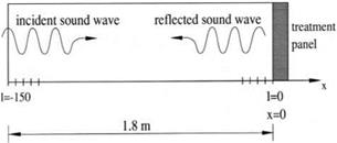
To illustrate how well the time-domain impedance boundary condition works, consider an initial value problem associated with the normal-incidence impedance tube (see Figure 10.9). An impedance tube is designed to measure the impedance of an acoustic liner sample. Let the length of the impedance tube be 1.8 m. The speed of sound at room temperature is 340 m/s. To ensure that there are at least 7 mesh points per wavelength in the computation for sound frequency up to 4 kHz, the impedance tube is divided into 150 mesh spacings yielding Ax = 0.012 m. In this example Ax is used as the length scale; i. e., L = Ax. The impedance of the treatment panel is taken to be R = 0.18, X_x = -0.47567, and X1 = 2.09236 (a is nondimensionalized by a0/Ax). These are values corresponding to those of Figure 10.2. At time t = 0, a transient acoustic pulse is generated. This produces a broadband pressure field in the frequency domain. A part of the acoustic pulse propagates down the tube and impinges on the acoustic treatment panel on the right. This leads to a partially reflected pulse. It will be assumed that the disturbance is generated by the following initial conditions at t = 0:
u = 0, p = e_0 00444(x+83333)2 cos [0.444 (x + 83.333)]. (10.29)
Figure 10.9. A normal incidence impedance tube.
 This choice of initial conditions ensures that the center of the acoustic spectrum of the incident wave at the surface of the acoustic treatment panel has a frequency of 2 kHz and a spectrum half-width of 0.5 kHz The impedance tube problem has an exact solution, which may be derived as follows.
 |
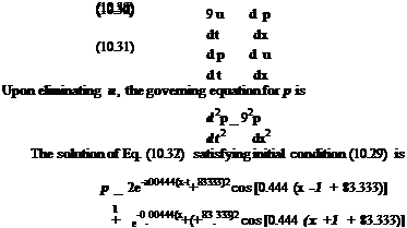
The governing equations for the acoustic field are the one-dimensional version of Eqs. (10.6) and (10.7). They are
The first term of Eq. (10.33) is the part of the pulse that propagates in the positive x direction. This is the sound pulse that impinges on the acoustically treated panel at x _ 0. For convenience, a subscript “inc” will be used to label the incident acoustic field, a subscript “ref” will be used to label the reflected field. Thus, the incident wave is
1
pmc _ umc _ 2e-000444(x-t+83’333)2 cos [0.444 (x – t + 83.333)]. (10.34)
Let
![]() pref _ – uref _ Ф(x + t).
pref _ – uref _ Ф(x + t).
Eq. (10.35) is a general solution of Eq. (10.32). At the impedance surface, x _ 0, the Laplace transforms of the incident and reflected acoustic field variables are

On imposing the impedance boundary condition (10.1), one finds
(pmc + p ref ) = 7(umc + uref )• (10.38)
On using Eqs. (10.36) and (10.37), it is found that
7 — 1
Ф = 77+^1 P’mc^ (10.39)
The exact solution is obtained by taking the inverse transform of (10.39) and adjust the argument according to Eq. (10.35). This gives
|
/ |

![]() (7 — 1)
(7 — 1)
g—56.265(®+0.444)2 + g—56.265(®—0.444)2
(7 + 1)L + –
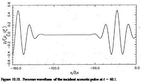
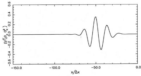
Figure 10.10 shows the computed pressure distribution at time t = 60.1. At this time, the left half of the initial pulse is about to exit the computational domain, whereas the right half of the pulse is about to impinge on the surface of the treatment panel. The dotted curve is the exact solution. Figure 10.11 shows the reflected pulse propagating away from the impedance boundary of the tube at t = 140.1. The amplitude of the reflected pulse is considerably smaller than that of the incident pulse. Part of the acoustic energy is dissipated off the impedance surface during the reflection process. The exact solution is represented by the dotted curve (the dotted curve is difficult to see because it is almost identical to the computed result). There is excellent agreement between numerical results and the exact solution. This is true for both the wave amplitude and phase. This example provides confidence in the use of time-domain impedance boundary condition.
|
Figure 10.11. Pressure waveform of the reflected acoustic pulse at t = 140.1. |


