Flat Plate/Ramp: Length of the Separation Zone
We have seen in the previous section that the thermal state of the surface, in particular the surface temperature, leads to a reduction of the skin friction, but to an increase of the size of the strong-interaction zone around the hinge line of a deflected wing flap.
The deflected flap constitutes a supersonic compression ramp, idealized as a flat plate/ramp configuration. The strong interaction around the hinge line is an Edney type VI interaction, Fig. 9.6 c) in Sub-section 9.2.1. We discuss results of experimental and numerical investigations of the influence of the surface temperature on such a M= 7.7 flow. The experimental investigation was made in the shock tunnel TH2 of the Shock Wave Laboratory of the RWTH Aachen University, Germany. The model is a flat plate/ramp model with internal electrical resistance heating. The ramp angle is 15°.
In Fig. 10.5 the results in terms of the (local) separation and attachment points illustrate the effect [8, 9]. The flow parameters are given in Table 10.6. The flow basically is laminar.
|
Table 10.6. Flow parameters of the flat plate/ramp case [8, 9].
|
The wall temperature ratio is 0.2 A Tw/Tt A 0.666 with Tt = 1,500 K. With increasing surface temperature the length of the separation region Lsep becomes larger. Lsep = 0 defines the corner point (hinge line) of the ramp, which lies 21.6 cm downstream of the sharp leading edge. Also a ramp with
10.5 cm length was employed.
The separation point (point S in Fig. 9.6 c) on page 343) moves upstream and the reattachment point (point A) less strongly downstream. The experimental and the numerical data are in good agreement. The upstream
Fig. 10.5. Experimentally and numerically determined separation and reattachment points on a ramp configuration as function of the surface temperature Tw /T0 (To = Tt) [8, 9].
movement of the separation point is due to the fact that the hotter the surface, the smaller the density in the flow near the surface. This reduces the momentum flux of the boundary layer and hence its ability to negotiate the adverse pressure gradient induced by the ramp.
A detailed account of the experimental work is given in [10]. We discuss only three figures from that publication in order to further illustrate the thermal surface effect. The flow parameters are given in Table 10.7.
|
Table 10.7. Flow parameters of the experimental flat plate/ramp cases [10].
|
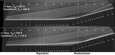
Fig. 10.6 shows typical schlieren pictures for the reference conditions II (upper picture) and I (lower picture). The flat plate/ramp model was heated such that different ratios ‘wall temperature’ to ‘free-stream temperature’ resulted. This ratio is the relevant similarity parameter regarding viscous thermal surface effects, Section 4.4. In the upper picture that ratio is Tw/T^ = 1.15, in the lower Tw/Тж = 6.77.
The schlieren pictures, Fig. 10.6, indicate well the influence of the different temperature ratios Tw/Тж. The barely visible thin short broken lines left indicate the separation shock, see also Fig. 9.6 c), and the thin long broken lines the separation zone.
|
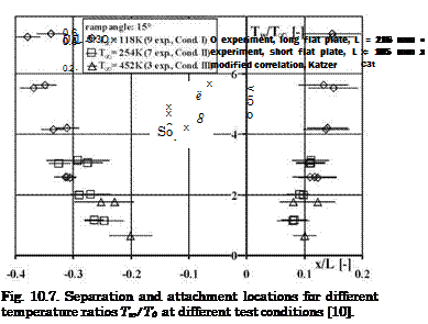
Fig. 10.6. Typical schlieren pictures of the flat plate/ramp flow [10]. Upper picture: condition II, Tw = 293 K, T’x = 254 K, Tw/T’x = 1.15, lower picture: condition I, Tw = 799 K, T^ = 118 K, Tw/T’ж = 6.77. |
The separation and attachment locations as function of the temperature ratio Tw/TЖ are given in Fig. 10.7. The figure looks quite similar to Fig. 10.5. The data of the upper schlieren picture with Tw/TЖ = 1.15 are the second from below, and those for the lower one with Tw/Tж = 6.77 the ones above.
In [10] the experimentally found lengths of the separation zones LB were compared with those found with a correlation due to E. Katzer for the adiabatic wall [11]. The authors of [10] have modified that correlation in order to take into account the influence of the wall temperature. The length LB is the straight distance between the points S and A in Fig. 9.6 c) on page 343.
Given in Fig. 10.8 are the experimentally found ratios LB/L as function of Tw/TЖ together with those found with the modified Katzer correlation. The data agree fairly well. Also the data found with the shorter flat plate fit in well. They were obtained in order to clarify questions regarding free shear-layer transition effects.
 |
7 8
Tw/Too
Fig. 10.8. Ratio of the length Lb of the separation zone to the length of the flat plate L as function of the temperature ratio Tw/Tо [10].


