Testing Procedures
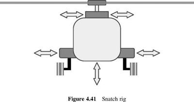
When a new helicopter design has been built to the first prototype stage it is usual to verify that it is not susceptible to ground resonance. In the past, the airframe was stripped to a minimum all-up weight. This uses the result that the lighter the helicopter, the greater the ground resonance vibration. The aircraft is then installed in a rig – known as a snatch rig – which attaches cables to strong points on the airframe. The rotor is gradually increased in speed and the pilot applies a cyclic pitch input to trigger flapping and hence lagging motion of the blades. The behaviour of the aircraft is then monitored for any sign of instability. This is repeated over a rotor speed range and also a range of collective pitch values so that the effect of reduced undercarriage load can be ascertained. Should instability be anticipated, the cables are pulled tight by a set of actuators such as hydraulic jacks. This causes the natural frequency of the fuselage to be raised moving the aircraft clear of the regressive lag mode. A schematic of a typical snatch rig is shown in Figure 4.41. The arrows show possible attachments to the airframe.
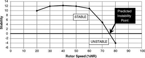
Prediction techniques and instrumentation have improved significantly since then and a helicopter can be cleared for ground resonance by monitoring the timewise fuselage and/or rotor blade motion directly. This information can be analysed very rapidly giving the condition of the helicopter in terms of ground resonance stability. The results will then
|
|
|
Figure 4.42 Example plot of locating incipient ground resonance |
give the stability variation with respect to rotor speed. Figure 4.42 shows a possible variation and the behaviour of the curve approaching the axis gives an indication of an incipient instability.
References
1. Saunders, G. H. (1975) Dynamics of Helicopter Flight, John Wiley & Sons, Inc.
2. Coleman, R. P. and Feingold, A. M.(1958) Theory of self-excited mechanical oscillations of helicopter rotors with hinged blades, NACA Report TN-1351.


