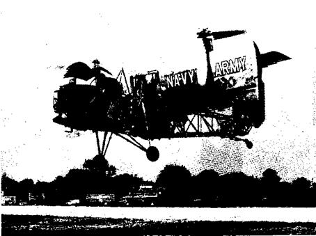
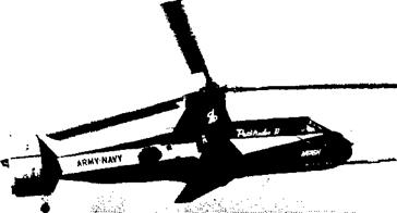
The abbreviation V/STOL is a combination of two other abbreviations, VTOL and STOL, which stand for “vertical takeoff and landing’’and “short takeoff and landing.” Thus V/STOL aerodynamics refers to an area of the subject of aerodynamics that is of special interest to the design of aircraft with vertical takeoff and landing or short takeoff and landing capabilities.
V/STOL aerodynamics is concerned primarily with the production of lift at low forward velocities. There is a qualification to the production of this lift, however. It is not to be accomplished at a sacrifice in the cruising performance of the aircraft. Hence an aircraft with low takeoff and landing speeds because of low wing loading would not, in general, be termed a “short takeoff and landing” aircraft. A vertical or short takeoff and landing aircraft employs some special kind of device to produce lift at low speeds. Here, the term “lift” is used in a general sense to denote the vertical force that sustains the aircraft in flight. It might be composed of the usual lift from a lifting surface and a force produced by some form of propulsor.
It has been axiomatic in the gradual development of aircraft that their landing speeds and distances have increased in proportion to their cruising speeds. The requirement for longer and longer runways is in direct conflict with the growth of metropolitan areas. The need for a type of aircraft with exceptional takeoff and landing performance is apparent. The logistics of modern warfare also require aircraft that can operate from small prepared or unprepared fields.
The development of such aircraft has proceeded rapidly with the introduction of suitable power plants. In particular, the gas turbine, with its low specific weight, that is, pounds of engine weight per pound of static thrust, has made possible the development of aircraft with static thrust to gross weight ratios greater than one. As the speeds of aircraft continue to increase, the power plant requirements for V/STOL operation and forward flight
I
performance become compatible. Above Mach 1 the thrust required is nearly equal to or exceeds the gross weight of the aircraft. However, for subsonic aircraft the installed thrust needed for V/STOL performance normally exceeds that required for efficient cruise. For these applications, therefore, the aerodynamicist must consider means of improving the cruise performance.
The many convincing arguments that can be put forward in favor of the VTOL aircraft are based mainly on the removal of equipment and facilities that are required to accomplish the conventional landing. These include the conventional landing gear, with its array of mechanical, hydraulic, electrical,
|

Fig. 1-1. STOL landing performance.
|
and pneumatic devices, and high-lift devices such as flaps, slats, and boundary layer control. The modern high-performance, conventional jet aircraft landing at speeds of the order of 150 to 200 knots requires runways in the 10,000-ft class. The problems of acquiring and maintaining such facilities and of braking the aircraft landing at these high speeds can be circumvented by the application of STOL and VTOL principles.
Investigators in the field differ in their opinions of an exact definition of a STOL aircraft. Most of them agree qualitatively on the characteristics a STOL aircraft must possess. It must be capable of takeoff and landing in a prescribed distance over a standard obstacle height, and the ratio of cruise speed to landing speed must be above a prescribed minimum. To fill these requirements simultaneously a STOL aircraft must possess some special design feature that will allow the development of lift at low speeds in excess of that developed by an ordinary wing.
A height frequently specified in takeoff and landing calculations is 50 ft. The horizontal distance to clear this obstacle height for STOL aircraft has been specified for some applications as 500 ft. However, this distance, as well as the ratio of cruising speed to landing speed, is not so well defined as the obstacle height. The reason is apparent. A turbojet fighter aircraft that might have a speed ratio of 20 and land in 1500 ft could be considered just as much of a STOL aircraft as a short-haul transport that can land in 500 ft but might have a speed ratio of only 6 or 7.
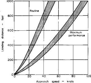
Consider the landing capabilities of STOL aircraft as shown in Fig. 1-1 [1].[1] This figure is derived from consideration of human response times obtained from actual flight tests with helicopters which showed that rates of descent of 500 to 700 fpm were the maximum that could be used with consistency. These limitations were derived from instrument approaches at altitude but are comparable to the highest rates of descent that can be used in the last 50 ft of altitude in an approach.
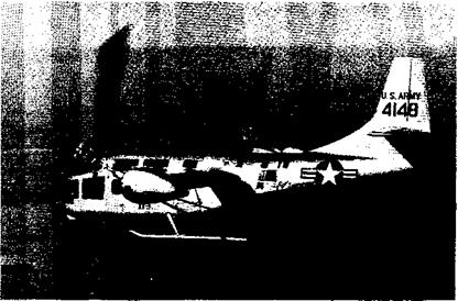
From this figure it can be seen that to land in 500 ft as a matter of routine requires an approach speed of approximately 30 knots. This assumes a rate of descent of 500 fpm, a circular arc transition with a normal acceleration of 0.1 g, and a stopping deceleration of 0.3 g. By the use of maximum techniques this approach speed can be increased to approximately 60 knots, which assumes a 1000-fpm rate of descent with no transition and a deceleration of 0.8 g. These assumptions are certainly on the optimistic side, and it would appear that the 30-knot approach speed is more realistic. In actual practice, however, the performance will probably be somewhere between these two extremes. The landing gear might be designed to withstand a rate of descent of approximately 700 to 800 fpm, and by reversing the propellers or thrust the deceleration could be increased to 0.5 or 0.6 g. Therefore an approach speed of 45 knots is representative of a STOL aircraft that would satisfy the landing requirement of 500 ft over a 50-ft obstacle. For example, one STOL reconnaisance aircraft, operational at the time of this writing, has a guaranteed landing distance over 50 ft of 775 ft for a stalling speed of 55 knots.
Additional insight into the factors influencing the takeoff or landing performance of an aircraft can be gained by a simplified analysis of the ground-roll distance of a landing aircraft. If TR is the reverse thrust, /і, the coefficient of braking friction, W, the weight of the aircraft, and V, the velocity at time t, then the equation of motion of the aircraft is
^ „ W dV
HF = 37
g dt
This equation integrates to
V0 is the initial velocity of the aircraft in the s-direction at touchdown. The distance S0 required for the aircraft to come to rest is found from
This equation assumes that TR is a constant and neglects any lift produced during the ground roll. It shows that the work performed by the retarding forces must equal the initial kinetic energy of the aircraft. It also clearly illustrates the importance of keeping V0 as small as possible, for the ground – roll distance S0 varies as the square of V0.
If V0 is taken to be 20% higher than the stalling speed, the distance S can be written as
TR is normally a function of the installed forward thrust. Because cruising requirements usually determine the thrust and the wing loading, it follows that the principal parameter in determining the landing distance, and the one over which the most control can be exercised, is the maximum lift coefficient. From this simplified analysis it can be seen that the landing distance might be expected to vary inversely with CLmax.


