Category Airplane Stability and Control, Second Edition

Landing Approach and Turn Studies

There is a large class of advanced flying qualities studies that has benefitted from modern pilot-in-the-loop technology without requiring delay-lead-lag mathematical models for the pilot. For loop closures made at frequencies of 1.0 radian per second or lower, simple gain models for the pilot appear adequate. Low-frequency closed loops characterize airspeed and path control outer loops.

STOL (short takeoff and landing) flight path control loops are the outer loops around higher frequency pitch attitude inner loops. The path loops can be closed with simple pilot

gains, assuming tight control of the inner loop (Ashkenas, 1988). Where some modest pilot lead is required to achieve the ideal integrator-type pilot-airplane transfer function in the crossover region, pilot ratings will be degraded.

Wings-level turn and turn coordination studies fall into the same category of low – frequency closed loops for which simple gain pilot models are adequate. The Ashkenas – Durand reversal parameter and the Heffley closed-loop studies of the naval carrier approach problem (Chapter 12) are yet additional examples of the use of simple pilot gain models.

Stability and Control Research Institutions

Stability and control research is carried out worldwide in a variety of institutions. There are the governmental laboratories and privately owned research firms that are found in almost every country where airplanes are built. Universities are also major centers of

Stability and Control Research Institutions

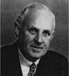
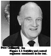
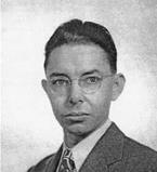
Irving L. Ashkenas


Stability and Control Research Institutions

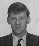
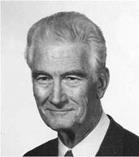
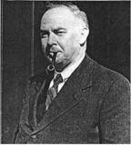
Leonard Bairstow


Stability and Control Research Institutions

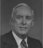
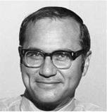
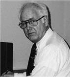
Arthur G. Barnes


Stability and Control Research Institutions

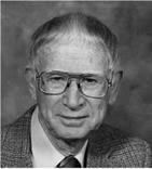
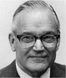
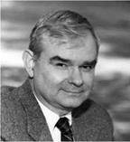
Waldemar O. Brehaus


Stability and Control Research Institutions

Michael V. Cook


Stability and Control Research Institutions

Stability and Control Research Institutions

William J. Duncan


Stability and Control Research Institutions

Bernard Etkin


Stability and Control Research Institutions

Stability and Control Research Institutions

Stability and Control Research Institutions

Duane T. McRuer


Stability and Control Research Institutions

Steven Osder


Stability and Control Research Institutions

Courtland D. Perkins


Stability and Control Research Institutions

William H. Phillips


Stability and Control Research Institutions

Lloyd D. Reid


Stability and Control Research Institutions

Ernest F. Relf


Stability and Control Research Institutions

Jan Roskam


Stability and Control Research Institutions

Robert F. Stengal


A. Jean Ross

Stability and Control Research Institutions

Roland J. White


Stability and Control Research Institutions

Fred C. Weick

Figure 2.1 (continued)


Stability and Control Research Institutions

Charles H. Zimmerman


Stability and Control Research Institutions

research. One can assume that any university where stability and control is in the curriculum has corresponding faculty or graduate research projects. Finally, aircraft manufacturers can be assumed to have stability and control research in progress at some level, depending on how advanced their products are.

As in many research areas, the lines of responsibility are blurred by cooperative projects among the three groups mentioned – laboratories, universities, and manufacturers. This is especially true when expensive or unique equipment is involved. A prime example is the regulated use of large governmental wind tunnels for aircraft that will enter production, rather than be used for research. Another example is the use of the highly specialized in­flight simulators operated by governmental and private laboratories to improve the flying qualities of future production aircraft.

The world-wide extent of stability and control institutions is evident in the sources named for reports and papers in the References and Core Bibliography section of this book.

Overhang or Leading-Edge Balances

When control surface area ahead of the hinge line is distributed along the span of the control surface, instead of in a horn at the tip, the balance is called an overhang or a leading-edge balance. Overhang design parameters are the percentage of area ahead of the hinge line relative to the total control surface area and the cross-sectional shape of the overhang (Figure 5.4).

Experimental data on the effects of overhang balances on hinge moments and control effectiveness started to be collected as far back as the late 1920s. Some of these early data are given by Abe Silverstein and S. Katzoff (1940). Airplane manufacturers made their own correlations of the effects of overhang balances, notably at the Douglas Aircraft Company (Root, 1939). As in many other disciplines, the pressure of World War II accelerated these developments. Root and hisgroup at Douglasfound optimized overhang balance proportions for the SBD-1 Dauntless dive bomber by providing for adjustments on hinge line location and overhang nose shape on the SBD-1 prototype, known as the XBT-2.

Root wrote a NACA Advance Confidential Report in May 1942 to document a long series of control surface and other modifications leading to flying qualities that satisfied Navy test pilots. For example, in 1 of 12 horizontal tail modifications that were flight tested, the elevator overhang was changed from an elliptical to a “radial,” or more blunt, cross­section, to provide more aerodynamic balancing for small elevator movements. This was to reduce control forces at high airspeeds.

Overhang aerodynamic balance, in combination with spring tabs, continue in use in Douglas transport airplanes, from the DC-6 and DC-7 series right up to the elevators and ailerons of the jet-powered DC-8. The DC-8’s elevator is balanced by a 35-percent elliptical nose overhang balance. Remarkably constant hinge moment coefficient variations with elevator deflection are obtained up to a Mach number of 0.96.

George S. Schairer came to the Boeing Company with an extensive control surface development background at Convair and in the Cal Tech GALCIT 10-foot wind tunnel. Although early B-17s had used spring tabs, Schairer decided to switch to leading-edge

Overhang or Leading-Edge Balances

Figure 5.4 Typical hinge momentparametervariation with size for leading-edge or overhang aerody­namic balances. The round nose is more effective in reducing hinge moment due to surface deflection Ch& than the elliptical nose, which does not protrude into the airstream as much when the surface is deflected. (From Phillips, NACA Rept. 927, 1948)

balances for the B-17E and the B-29 bombers. The rounded nose overhang balances on the B-29s worked generally well, except for an elevator overbalance tendency at large deflection angles. Large elevator angles were used in push-overs into dives for evasive action. William Cook remarks, “A World War II B-29 pilot friend of mine was quite familiar with this characteristic, so the fact that he got back meant this must have been tolerable.” However, overhang balance was not effective for the B-29 ailerons. Forces were excessive.

The wartime and other work on overhang aerodynamic balance was summarized by the NACA Langley Research Department (Toll, 1947). The Toll report remains a useful reference for modern stability and control designers working with overhang aerodynamic balances and other aerodynamic balance types as well.

Generalized Panel Methods

Following the pioneering vortex lattice work, computational fluid dynamics pro­grams of increasing complexity have been developed, such as PAN AIR by Boeing, QUADPAN at Lockheed, Analytical Methods, Inc.’s, VSAERO, and MCAERO at McDonnell-Douglas. These approaches have included the Neumann problem in potential flow (Smith, 1962), inviscid Euler methods (Jameson, 1981), and full-blown Navier-Stokes equation solutions (Pulliam, 1989).

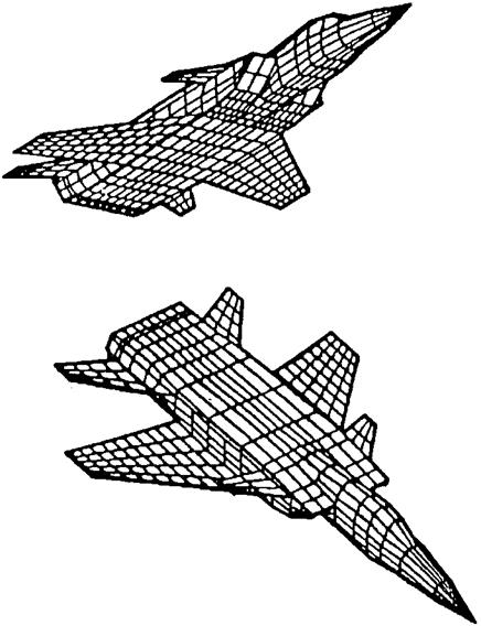
Vortex lattice, Euler, and Navier-Stokes methods are now used to generate airplane stability and control data at the preliminary design stage in much the same way that wind-tunnel models were used in earlier times. The computer defines and stores the three-dimensional panel geometry approximating the airframe shape, as in Figure 6.4. Aircraft lift curve slopes, static longitudinal and lateral stability, control effectiveness, and even rotary derivatives are well predicted for small angles of attack, sideslip, and control deflection.

6.1 Estimation from Wind-Tunnel Data

Manufacturers of transport and military airplanes spend a great deal of money and engineering effort on wind-tunnel testing in developing new designs. These costs are rarely questioned anymore; one just budgets wind-tunnel testing at a generous level. Yet, how well can one expect wind-tunnel test results to match stability and control flight test results? This question was dealt with in an early NACA study (Kayten and Koven, 1945). Both engineers later led the stability and control branch in the U. S. Naval Air Systems Command.

Kayten and Koven compared wind-tunnel and flight test measurements for the Douglas A-26 Invader twin-engine attack airplane. The discrepancies were larger than one might have expected. Most of the discrepancies could be explained after the fact, but one is left with the uneasy feeling that wind-tunnel tests can give engineers a distinctly cloudy crystal ball. The factors that led to discrepancies in the case of the A-26 were

1. The geometric wing dihedral was greater in flight than in the wind tunnel due to upward bending under load. This problem could be dealt with by giving tunnel models extra wing dihedral based on calculated bending deflections.

Generalized Panel Methods

Figure 6.4 PAN AIR panel geometry for a computational fluid dynamic analysis of a complete airplane configuration. (From Tinico, Boeing Commercial Airplane Group, 1992)

2. Control surface contours in flight differed from the wind-tunnel model because of fabric distortion. Thisproblem mayhave effectivelyvanished, since fabric-covered control surfaces are now rarely used.

3. There was premature inboard wing stalling in flight that was not present on the smooth, well-faired wind-tunnel model wing. This last problem is of the type that is difficult to deal with in advance. However, the current approach might be to clean up the airplane’s premature wing stalling by refairing or vortex generators, incidentally bringing about better agreement between the wind-tunnel and flight data.

In spite of discrepancies such as these, designers ignore unfavorable wind-tunnel results at their peril. For example, before it was flown, power model tests of the Martin 202 showed that its one-piece wing would have negative effective dihedral in the power approach condition. The results were dismissed with the comment, “It’s only a wind – tunnel test,” but an expensive redesign was needed later.

CHAPTER 7

Vortex Effects and Self-Induced Wing Rock

Self-induced wing rock on slender delta wings was observed first at NASA’s Langley Research Center in the late 1940s, in the free-flight wind tunnel. Wing rock ap­peared as a limit cycle, or undamped, roll oscillation at angles of attack below the stall. We know now that wing rock is typically associated with separated flows and time-dependent effects.

Because of interest in both supersonic transports and reentry vehicles, research activities into wing rock continued in both the United States and the United Kingdom (Ross, 1988). Attention turned later to combat airplanes, where wing rock was thought to have contributed to loss of control in high angle of attack maneuvers. Attempts to alleviate wing rock by stability augmentation have been successful, as in the case of the Grumman X-29A research airplane (Clarke, 1996).

However, attempts to correct the problem aerodynamically have been less successful because of the complex flow mechanisms involved. On the X-29A, the driving mechanism for wing rock was determined to be the interaction of vortices from the forebody with other components, as was the case for the Northrop F-5, at low airspeeds. On the other hand, a high-airspeed wing rock of the F-5 was driven by shock-induced separation on the wing. Some measurements indicate asymmetry of the vortices shed from wing leading edges as driving the motion, with vortex breakdown limiting the motion’s amplitude (Ericsson, 1993). Dr. Ericsson is a leading expert and prolific author on the effects of unsteady flows on stability and control.

It turns out that self-induced wing rock can also occur on very low-aspect-ratio rectan­gular wings, caused by vortices shed from the side edges. This is interesting but academic, since rectangular wings of aspect ratio less than 0.5 have never been considered for actual airplanes or missiles. What is decidedly not academic is the role of highly swept wing leading-edge extensions, or LEXs, in wing rock and other undesirable behavior. Wing leading-edge extensions were pioneered on the Northrop YF-17 and F-5 airplanes to in­crease maximum lift and reduce drag at high lift, by vortex interactions with the main wing surface. Wing leading-edge extensions have gone on to be used on many other modern fighter airplanes, such as the F/A-18. The highly swept side inlets of the Russian MiG-25 airplane act as leading-edge extensions, developing vortices at high angles of attack.

Wing rock is often studied in wind-tunnel tests in which a model is mounted on low – friction roll bearings and is free to roll. Forced roll oscillations can also reveal the wing rock tendency by regions of negative roll damping or positive signs of the rotary derivative Clp. A comparison between wing rock amplitude measurements on a free-to-roll model F-18 in a wind tunnel and on the F/A-18 HARV (High Angle of Attack Research Vehicle) in flight shows good agreement (Nelson and Arena, 1992). There was also a fair correlation for (reduced) frequency between wind-tunnel and flight testing. This supports the notion that flow conditions during flight wing rock are close to the single-degree-of-freedom wind – tunnel conditions.

Contradicting the reasonable correlation of F/A-18 HARV single-degree-of-freedom wind-tunnel tests and flight test measurements of wing rock is the finding on the F-4, Tornado, and RAE HIRM (High Incidence Research Model) that wing rock occurs at frequencies close to those of the classical Dutch roll. This is unusual since wing rock is a nonlinear limit cycle, while the Dutch roll is consistent with linearized equations of motion and requires roll, sideslip, and yaw degrees of freedom.

In addition to the wing rock phenomenon, vortex bursting at high angles of attack has undesirable effects, such as loss in lift and negative dihedral effects. Vortex bursting is associated with leading-edge sweep angles less than about 75 degrees. The interactions of wing leading-edge vortices with other airplane components of modern fighter airplanes is covered in a comprehensive paper by Andrew M. Skow and G. E. Ericson (1982). A more recent review was provided in 1992 by John E. Lamar, published in AGARD Report 783.

Lamar finds that the leading-edge suction analogy, first proposed by Edward C. Polhamus in 1966, providesa powerful tool for estimating aerodynamic forcesand momentsfor sharply swept wings with vortex flows. It appears that the leading-edge suction force in attached flow is reoriented in the direction of the rotating vortex, when the vortex forms. Typically, lift and moment terms using the analogy are added to linear aerodynamic and vortex lattice computer codes.

Direct Lift Control

Direct lift control, in which airplane lift is modulated to correct flight path errors without changing airplane angle of attack, seems to be a natural solution to carrier-approach path control problems. According to William Koven, the first proposal for direct lift control on carrier airplanes came from Douglas E. Drake, a Douglas Aircraft engineer and former Navy pilot. Professor Edward Seckel directed follow-up studies at Princeton University. Direct lift control was first tested on a carrier-based airplane in 1964. This was a Ling – Temco-Vought F-8C, modified for the ailerons to act as variable flaps. That work was done by J. D. Etheridge and C. E. Mattlage.

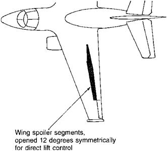
The production Lockheed S-3A Viking has direct lift control, to aid in carrier landing approaches. On the S-3A, quite rapid flight path corrections are made by moving both wing spoilers, changing wing lift without changing the angle of attack (Figure 12.4). With direct lift control there is no need to wait for the airplane to respond in pitch to elevator motion, a response that takes place at the short-period pitching frequency of the airplane. A button on the S-3A pilot’s yoke commands symmetric spoiler deflection.

In contrast to the relatively crude button-operated S-3A direct lift control system, a sophisticated, integrated, direct lift system is used on the Lockheed 1011 Tristar, which is fitted with the Collins FCS-240 digital automatic pilot. This Collins system, incorporating

Direct Lift Control

Figure 12.4 Direct lift control using wing spoilers provide satisfactory path control for carrier land­ings on the Lockheed S-3A Viking. (From Jane’s All the World’s Aircraft)

automatic landings or autoland, was originally developed for the L-1011 ’s European market, where the winter months require frequent low-visibility landings. The FAA certified the L-1011 for Category IIIA (ceiling zero, visibility 700 feet) landings in 1981.

When the pilot selects landing flaps the four inboard wing spoiler segments are rigged up to an 8-degree position. They are then modulated upward and downward from the up-rigged position to obtain direct lift control. Spoiler angle changes from the up-rigged position are commanded by the cockpit control column moved either by the pilot or the autopilot’s autoland mode, in the normal sense. That is, back control column motion closes the spoilers and the airplane gains altitude.

If a control column adjustment is sustained for several seconds, the spoiler segment deflections from their up-rigged positions are gradually washed out and a corresponding adjustment is made to the horizontal tail angle. In the case of a sustained rearward control column motion, the washout moves the spoilers back up to their up-rigged positions of 8 degrees and the horizontal tail angle is increased in the airplane nose-up sense. The Tristar’s period in the short-period pitching mode is a full 8 seconds at landing approach airspeeds. Pitch and path corrections by horizontal tail control alone would take place at that modal period, or rather slowly. Direct lift control provides a faster path response for demanding all-weather manual or automatic landings. In contrast to the S-3A case where the pilot controls vertical path with the direct lift button as well as control column motion, in the integrated L-1011 case there is only one pilot controller, the control column.

What is missing in considering direct lift control for any airplane, carrier – or land-based, is a method that determines when that feature is needed. What combinations of pitch and thrust responses are such that direct lift control is required to meet specific vertical path control requirements?

Artificial Horizon, Directional Gyro, and Autopilots

The history of intentional blind flying began with Jimmy Doolittle’s flight in a Consolidated NY-2 in September 1929. The airplane was equipped with two gyroscopic instruments, a gyro horizon and a directional gyro. Both have free gyroscopic wheels, which tend to preserve their position in inertial space. The wheels are mounted in double gimbals so that the airplane is free to rotate about them. The relative rotation is displayed on the instrument faces. Legal IFR flight in an airplane with a standard-category U. S. airworthiness certificate requires airplanes to be equipped with these instruments.

Recent developments in inertial navigation with strapped-down laser gyros and attitude determination by the Global Positioning System (GPS) provide synthetic versions of the artificial horizon and directional gyro. Autopilots use these instruments or their synthetic versions in automatic blind flying.

Steady-State Solutions

Steady-state solutions to the equations of airplane motion are defined as motions with zero values ofbody axis linear and angular accelerations. Steady straight flight includes climbing, level flight, and diving and allows the airplane to have a nonzero sideslip angle. Steady turning flight allowsconstant valuesof the three body axisangular velocities, yawing, pitching, and rolling.

SUBROUTINE INTG2

C MODIFIED SECOND-ORDER RUNGE-KUTTA INTEGRATION DIMENSION Q(40),DQ(40)

C STORE STARTING VALUES DO 1 I = 1 ,N Q(D=X(I)

DO(l) = F(l)

C ESTIMATE STATES AT MIDPOINT X(I) = X(I) + (DT/2.)*F(I)

1 CONTINUE

C CALCULATE STATE DERIVATIVES AT MIDPOINT CALL DERV1

C UPDATE STATES, START TO ENDPT, WITH MIDPT DERIV’S DO 2 1 = 1,N X(I) = Q(I) + DT*F(I)

C PREDICTOR FOR STATES AT MIDPOINT F(I) = 1.5*F(I)-.5*DQ(I)

2 CONTINUE

C UPDATE THE TIME T = T + DT RETURN END

Figure 18.13 A modified second-order Runge-Kutta integration subroutine developed to run quickly, for use in real-time digital flight simulation. This FORTRAN subroutine was developed by A. F. Myers for NASA’s SIM2 simulation. Xis the state derivative vector. COMMON input-output statements have been removed for generality. (From ACA Systems, Inc. FLIGHT simulation)

Steady flight conditions are used as reference values for the perturbations of linearized analysis (Sec. 18.2). Applications are to root locus, frequency response, covariance prop­agation, and optimization. Steady flight conditions also establish initial state variables for nonlinear transient analysis, such as landing approaches, gust response, and pilot-initiated maneuvers. Finally, basic stability conditions can be deduced from the control surface an­gles required for steady flight. For example, spiral instability is implied when opposite aileron angle is required in a steady turn, such as left aileron to hold trim in a steady right turn.

Steady flight solutions are usually obtained for the nonlinear equations of motion by driving to zero selected body axis linear and angular accelerations. Stevens and Lewis (1992) apply a minimization algorithm called the simplex method for trim in steady, straight, symmetric (unsideslipped) flight. A cost function is formed from the sums of squares of the forward, vertical, and pitching accelerations. A multivariable optimization adjusts thrust, elevator angle, and angle of attack to minimize the cost function.

A closed-loop trimming method (Abzug, 1998) is an alternative to the simplex method. The nonlinear state equations are solved in sequence, together with control equations that adjust thrust, angles of attack and sideslip, and control surface angles to minimize acceler­ations. In the control equations, thrust is adjusted in small steps to minimize longitudinal acceleration, angle of attack is adjusted in small steps to minimize vertical acceleration, elevator angle is adjusted in small steps to minimize pitching acceleration, and so on.

Command Augmentation Systems

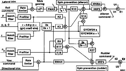
Command augmentation systems, or CAS, are a relatively recent form of airplane stability augmentation. Pilot control inputs, usually filtered or shaped, are compared with measured airplane motions, with the differences being sent to the control surface actuation servos (Figure 20.3). In early command augmentation applications, such as in the McDonnell Douglas F-4, F-15, and F-18 and the Rockwell B-1, the augmentation system has limited authority. There are parallel direct links from the sticks to the control surface servos.

Command Augmentation Systems

Figure 20.3 Block diagram for the lateral-directional command augmentation system for the X-29A research airplane. Key features are the rate-limiters on roll and yaw commands. These minimize the possibility of rate-limiting the control servos due to large pilot control inputs. (From Clarke, Burken, Bosworth, and Bauer, NASA TM 4598, 1994)

The command augmentation systems of later airplanes such as the fly-by-wire General Dynamics F-16 have full-authority and high-command gains. Full-authority roll command augmentation systems have worked very well, with sharp, rapid, and precise responses to control inputs (Mitchell and Hoh, 1984). Some problems come along with these successes. Oversensitivity to small inputs, overcontrol with large inputs, and the phenomenon called roll-ratcheting can occur.

Roll Response of Large Airplanes

Experience with C-5A roll response shows possible shortcomings of current re­quirements when applied to really large airplanes. William D. Grantham (1983) reports:

[Considerable effort and expense were initially expended on the C-5A in an attempt to meet a requirement for rolling to an 8 degree bank angle in one second. It was later determined from flight tests that the handling qualities of the C-5A were totally acceptable with less than one-half such roll capability.

This implies that careful research is needed to establish time-to-bank requirements for superjumbo jets, to avoid overdesign.