Category Airplane Stability and Control, Second Edition

Stability and Control of Hypersonic Airplanes

Hypersonic flight is generally understood to mean flight at Mach numbers above 5.0. The only experience with manned airplanes at hypersonic speeds has come from the North American/NASA X-15 and space shuttle Orbiter programs. Stability and control phenomena at hypersonic speeds are qualitatively no different than at moderate supersonic speeds. There is the same relative loss in the effectiveness of lifting stabilizing surfaces relative to fuselage-destabilizing moments. The high altitudes at which hypersonic flights are carried out lengthen the periods of uncontrolled motions, always a piloting problem.

The influence of the propulsion system on aerodynamic forces and moments is expected to be more extreme in powered hypersonic flight than at lower speeds. The reverse is also true in that slight sideslip angles could cause severe inlet problems, depending on details of the design. Sufficient control surface authority may be required to overcome yawing, pitching, and rolling moments caused by engine inlet unstarts precisely at altitudes where control moments are low because of low air density.

However, the most pressing stability and control problems of hypersonic airplanes are probably encountered at low speeds, as a result of the unique design features that go along with hypersonic flight. Wing slats or drooped leading edges that could improve low-speed longitudinal and directional stability are apparently ruled out because of aerodynamic heat­ing problems at seams in the forward lower wing surface. A hypersonic passenger airplane for long over-ocean flights remains an interesting, but probably distant, goal for aviation planners. The aerodynamic research that has gone into this concept so far has quite prop­erly dealt mostly with performance and aerodynamic heating. Conceptual designs that have been published show configurations that look like stretched-out space shuttle Orbiters.

The Role of Displays

While proper stability and control design, supplemented by artificial means such as control centering devices and wing levelers, are fundamental to safe airplanes, some

The Role of Displays

Figure 15.5 Aileron-centering device tested on a Cessna 190. The cylindrical barrel encloses two preloaded compression springs, overcoming control system friction to provide aileron centering. Trim and device engagement are both done manually by the pilot. (From Campbell, Hunter, Hewes, and Whitten, NACA Rept. 1092, 1952)

safety deficiencies can apparently be made up with the right kind of cockpit displays or instruments (Loschke, Barber, Enevoldson, and McMurty, 1974). They reported that on a light twin-engine airplane, a flight director display is of significant benefit during ILS approaches in turbulent air.

Heavy pilot workload during such approaches had been found in an earlier survey of general-aviation airplanes, making precise instrument tracking difficult even for experienced instrument pilots. However, the flight director instrument, which combines inputs from attitude and rate gyros and in effect tells the pilot how to move the controls, reduces somewhat this excessive workload. Even greater improvements in tracking during ILS approaches in turbulence are found when the flight director display is combined with an attitude-command autopilot.

The Role of Displays

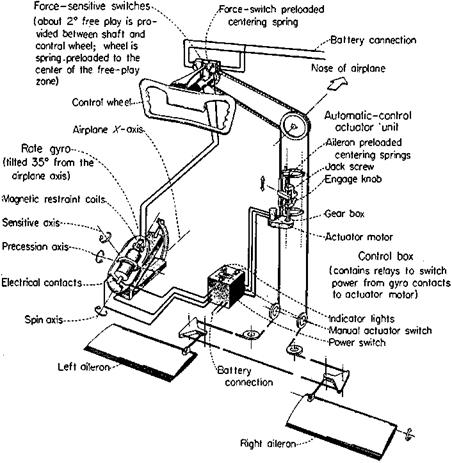
Figure 15.6 A wing-leveler device that works by moving aileron-centering springs at a low fixed rate in response to the measured rate of yaw. Wheel force switches improve maneuvers by precessing the gyro. The device was flown on a Cessna 190. (From Phillips, Kuehnel, and Whitten, NACA Rept. 1304, 1957).

The experiences of an airline pilot in operating heavily automated passenger-jet airplanes is relevant to the improvements provided by flight directors and automatic pilots for general – aviation airplanes. The question is how to use these devices to enhance safety for the average pilot under all operating conditions. William M. Ferree of Mount Vernon, New Hampshire, writes as follows (1994):

I’ve been a professional pilot for over 20 years and currently fly the Boeing 757 and 767. A high level of automation gives these excellent airplanes capabilities that would have been remarkable a few years ago. However, the design breaks down when some significant change of plan is introduced, which may happen because of an equipment failure or, more commonly, because of difficulty with the air traffic control system or the weather. The problem is that unless the computer is reprogrammed in these situations, it is useless. And reprogramming must often be done while landing preparation is being completed, which is an extremely busy time.

Ferree goes on to note that the 757 and 767 autopilot/flight director control panel consists of a few knobs for selecting things such as airspeed and altitude and many identical square push buttons. The panel cannot be operated by feel. The pilot must look at it in order to operate it. The argument for readily reprogrammed equipment in commercial-transport airplanes must be even more valid for general-aviation flight directors and automatic pilots.

Today’s heavily automated passenger jet airplanes have multifunction cathode ray or flat – screen displays of all flight and engine instruments, quadruplicated as backups for failure. Yet, a few old-style instruments are carried as additional insurance. All Boeing transports from the 707 on have small standby vacuum-driven gyro horizons, just to the side of the central instrument panel. This will give several minutes of reliable indication after a power failure, due to the inertia of the gyro’s rotor.

Another question related to automation of passenger jets is whether automation is re­ducing the competence needed in pilots. Wyatt Cook, an American Airlines pilot, reports that in flight training at the Dallas facility, one of the two pilots is required to be on raw data, meaning the VOR and ILS radio guidance signals. William H. Cook, Wyatt’s father, writes, “The basics [VOR and ILS] require a lot of work.”

Literal Approximations to the Modes

A literal approximation to a mode of airplane motion is defined as an approximate factor that is a combination of stability derivatives and flight parameters such as velocity or air density. This approximation is quite distinct from the factors that are obtained from the airplane’s fourth – or higher degree characteristic equations, factors that are necessarily in numerical form. Literal approximations to the modes have a long history, starting with Lanchester in 1908. A feedback systems analysis approach to developing and validating approximate modes was developed by Ashkenas and McRuer (1958).

A well-known and usually quite accurate literal approximation to the roll mode is for the roll mode time constant TR. The roll mode time constant is the time required for rolling velocity to rise to 63 percent of its steady value following an abrupt aileron displacement. The approximation is TR = -1 /Lp. The symbol Lp = Clpq Sb2/(2 VIx), where

Clp = dimensionless roll damping derivative, a function of wing planform para­meters such as aspect ratio and sweep angle; q = flight dynamic pressure, (p/2) V2;

S = wing area;

b = wing span;

V = flight velocity;

p = air density;

Ix = roll moment of inertia.

Note that all of the individual parameters in the roll mode approximation would nor­mally be known to an airplane designer. A large literature has been produced on literal approximations to the modes. McRuer (1973) lists four reasons for this interest, as follows:

1. Developing the insight required for the determination of airframe/automatic – control combinations that offer possible improvements on overall system complexity.

2. Assessing the effects of configuration changes on aircraft response and on air – frame/autopilot/pilot system characteristics.

3. Showing the detailed effects of particular stability derivatives (and their estimated accuracies) on the poles and zeros and hence on aircraft and air – frame/autopilot/pilot characteristics.

4. Obtaining stability derivatives from flight test data.

To this list one might add that mode approximations provide a reasonableness check on complete solutions generated within massive digital-computer programs, assuring that no input errors have been made. Literal approximations to the modes are obtainable only if the equations of motion themselves are simplified in some way, or if the factorization itself is approximated.

Mode approximations are useful in the ways McRuer lists as long as the approximations are simple ones, easy to grasp. One can improve the approximations, bringing the numerical values closer to the actual factors of the characteristic equation. This can provide additional insight into aircraft flight mechanics. However, if the literal expressions are lengthy, their utility suffers. The improvement to the classical Lanchester result for the phugoid mode period made by Regan (1993) and others (see Chapter 11, Sec. 13), which adds only one simple term but greatly improves accuracy at high airspeeds, is an example of a useful improved approximation, in the context of McRuer’s comments.

On the other hand, the improved modal approximations of Kamesh (1999) and Phillips (2000), while demonstrating considerable mathematical skills and adding to our under­standing of flight dynamics, are probably too complex for the applications mentioned by McRuer.

Early Experiments in Stability Augmentation

The first stability augmenters appeared during World War II. Little detailed in­formation is available about them. A German Blohm and Voss Bv 222 flying boat was thought to have had a pitch damper acting through a small, separate elevator surface. In a paper delivered in 1947, M. B. Morgan described an experimental yaw damper installed on a Gloster Meteor jet airplane. Other notable early designs were the Boeing B-47 and the Northrop YB-49 yaw dampers and the Northrop F-89 sideslip stability augmenter, which are discussed below.

20.5.1 The Boeing B-47 Yaw Damper

The B-47 Stratojet was a radical airplane in its time, a six-jet bomber with very flexible sweptback wings. Early flight tests disclosed that damping in yaw at low airspeeds was much less than pilots could deal with in landing approaches. The main pilot objection was to the rolling portion of the motion, caused by the dihedral effect of the swept wings at high angles of attack. After discarding other alternatives, Boeing engineers decided to attack the rolling motion indirectly, by artificial yaw damping using a rate gyro and the airplane’s rudder. That is, by suppressing side-slipping motions, the airplane’s rolling moment due to sideslip would not cause the objectionable wallowing in landing approaches.

The engineers who were chiefly responsible for the XB-47 yaw damper design were William H. Cook and Edward Pfafman. Roland J. White, who made a frequency-response analysis of the XB-47 yaw damper design, provides a complete account of the development (White, 1950). In White’s account one can find all of the elements that go into modern stability augmenter designs, even though in unfamiliar form in some cases. These are

the application of servomechanism analysis, using the equations of airplane motion;

airframe mathematical model includes aeroelastic bending effects; irreversible power controls;

stability augmentation series servo, isolating the pilot from the servo action; artificial feel system.

Roland White’s XB-47 yaw damper servomechanism analysis, using inverse frequency response, was advanced for its time. However, the all-important matter of loop gain, or commanded rudder angle per unit yaw rate, was apparently settled in flight test. William Cook remembers that Robert Robbins, the XB-47 test pilot, had a rheostat that varied yaw damper gain, and that Robbins chose the value that seemed to work best.

With no fund of stability augmenter design information to draw upon, Cook and Pfafman improvised the yaw damper both in terms of design requirements and hardware. A short phone call from Cook at the Moses Lake flight test site to Pfafman laid out the key design requirements of rudder damping authority (one-fourth of full travel) and series actuation. The yaw damper servo was an electric motor and amplifier that had been used for B-29 turbo-supercharger waste gate control (Figure 20.1).

White’s paper was delivered at the Design Session of the Institute of the Aeronautical Sciences 1949 Annual Summer Meeting in Los Angeles. The concept of stability augmen­tation as a normal design feature for swept-wing airplanes had not yet been established, and White’s paper irritated at least one purist. According to Duane McRuer, this person, a respected professor of design at Cal Tech, got off the following comment during the paper’s discussion period:

If the B-47 had been designed properly, it would not have needed electronic stability augmentation.

William H. Cook (1991) reports a similar reaction from an MIT professor, unhappy that an “artificial” solution had been used on the B-47 to solve an aerodynamic stability problem. Of course, there is a perfectly sound aerodynamic reason why yaw stability augmentation is needed on jet airplanes and is not an evidence of poor design. Approximately, Dutch roll damping ratio is directly proportional to atmospheric density. An airplane with a satisfactory damping ratio of 0.3 at sea level will have a damping ratio of only 0.06 at an altitude of 45,000 feet.

Fighters Without Vertical Tails

The designers of the B-2 stealth bomber proved that the stability and control requirements for a subsonic-level bomber can be met without vertical tails. What is not clear is whether the more severe fighter stability and control requirements can be met without vertical tails.

All designs in a USAF Wright Laboratory multirole fighter study have either small ver­tical tails or none at all (Figure 22.4) (Oliveri, 1994). The preferred replacement for normal vertical tails is thrust vectoring and split ailerons. These controls were used successfully on the NASA/Boeing X-36 Fighter Agility Research Aircraft. A 28-percent-scale remotely piloted model was flown in 1997, reaching an angle of attack of 40 degrees.

A thrust vectoring scheme used to replace fighter vertical tails must have a high – bandwidth actuator responding to sideslip signals for directional stability as well as other stability-augmentation system signals and commands from the pilot. Unless split ailerons are used, for safety reasons it would seem necessary for a thrust vectoring sideslip loop to provide directional stability even at idle thrust. Alternately, engine thrust could be di­verted left and right when idle thrust is needed and modulated for directional stability and control.

All in all, stability and control engineers should come well prepared at design meetings where stealth is the topic.