Category Airplane Stability and Control, Second Edition

Variable-Stability Airplanes Play a Part

A variable-stability airplane is a research airplane that can be made to have arti­ficially the stability and control characteristics of another airplane. Waldemar O. Breuhaus credits this invention to William M. Kauffman, at the NASA Ames Research Center, about the year 1946 (Breuhaus, 1990). The colorful story that Breuhaus tells is of Kauffman look­ing out of the window at the Ames flight ramp and seeing three Ryan FR-1 Fireball fighters sitting side by side. Each FR-1 had a different wing dihedral angle. The airplanes had been so modified to try to find in flight testing the minimum amount of effective dihedral angle that pilots would accept. Kauffman said, according to Steve Belsley and some others, “There has to be a better way.”

Ames modified a Grumman F6F-3 Hellcat into the first variable-stability airplane by a mechanism that moved the ailerons in response to measured sideslip angles. An electric servo motor, adapted from a B-29 gun turret drive, moved the F6F’s aileron push-pull rods in parallel to the pilot’s stick input. With this parallel arrangement, the pilot’s stick is carried along when the servo works in response to measured sideslip. This is suitable for automatic pilots, where it isoften acceptable and even desired for the pilot’scontrolsto reflect automatic pilot inputs. However, it does not serve the function of a variable-stability airplane, where the action of the variable-stability mechanism is supposed to be unnoticeable to the pilot.

In the case of the pioneering F6F-3 variable-stability airplane, pilot stick motions were suppressed approximately by an ingenious scheme that canceled the aerodynamic hinge moment corresponding to the commanded aileron deflection. This was done by driving the aileron tab through its own servo motor with a portion of the same signal that was used to drive the aileron push-pull rod.

The F6F-3 variable-stability airplane was followed in the next 30 years by at least 20 other airplanes of the same type. The majority were built by NACA/NASA; the Cornell Aeronautical Laboratories, later Calspan; the German Aerospace Center, or DLR; and the Royal Aircraft Establishment, later DERA. Princeton University, the Canadian National Research Council, Boeing, and research agencies in France and Japan also built them.

The crude compromises of the early machines have given way to ever more sophisticated ways of varying airplane stability and control as seen by the test pilot. Later models, such as the Calspan Total In-Flight Simulator, or TIFS, and the Princeton University Variable – Response Research Aircraft, or VRA, have special side-force generating surfaces.

Flying or Servo and Linked Tabs

Orville R. Dunn (1949) gave 30,000 pounds as a rule-of-thumb upper limit for the weight of transport airplanes using leading-edge aerodynamic balance. Dunn considered that airplanes larger than that would require some form of tab control, or else hydraulically boosted controls. The first really large airplane to rely on tab controls was the Douglas B-19 bomber, which flew first in 1941. The B-19 used pure flying or servo tab control on the rudder and elevator and a plain-linked tab on the ailerons. In a flying tab the pilot’s controls are connected only to the tab itself. The main control surfaces float freely; no portion of the pilot’s efforts go into moving them. A plain-linked tab on the other hand divides the pilot’s efforts in some proportion between the tab and the main surface. The rudder of the Douglas C-54 Skymaster transport uses a linked tab.

Roger D. Schaufele recalls some anxious moments at the time of the B-19’s first flight out of Clover Field, California. The pilot was Air Corps pilot Stanley Olmstead, an experienced hand with large airplanes. This experience almost led to disaster, as Olmstead “grabbed the yoke and rotated hard” at liftoff, as he had been accustomed to doing on other large airplanes. With the flying tab providing really light elevator forces, the B-19 rotated nose up to an estimated 15 to 18 degrees, in danger of stalling, before Olmstead reacted with forward control motion.

Flying tabs are quite effective in allowing large airplanes to be flown by pilot effort alone, although the B-19 actually carried along a backup hydraulic system. A strong disadvantage

is the lack of control over the main control surfaces at very low airspeeds, such as in taxi, the early part of takeoffs, and the rollout after landing. The linked tab is not much better in that the pilot gets control over the main surface only after the tab has gone to its stop. Still, by pro­viding control for the B-19, the world’s largest bomber in its time, flying and linked tabs, and the Douglas Aircraft Company engineers who applied them, deserve notice in this history.

An apocryphal story about the B-19 flying tab system illustrates the need for a skeptical view of flying tales. MIT’s Otto Koppen was said to have told of a B-19 vertical tail fitted to a B-23 bomber, an airplane the size of a DC-3, to check on the flying tab scheme. The point of the story is that the B-23 flew well with its huge vertical tail. Koppen said this proved that a vertical tail could not be made too large. Unfortunately, this never occurred. Orville Dunn pointed out that (1) the B-23 came years after the B-19, and (2) it didn’t happen.

The First Flight Occurrences

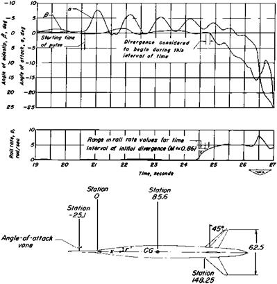
According to NACA, inertial coupling was first experienced in manned flight by NACA test pilot Joe Walker on the Douglas X-3 research airplane. However, Norman Bergrun and Paul Nickel of the NACA Ames Aeronautical Laboratory had made an earlier flight confirmation of the Phillips theory (1953). They found proof of the theory in the motions of an unmanned rolling body-tail combination tested at NACA’s High-Speed Flight Station at Edwards, California. As with the Douglas Mark 7 bomb test, the Bergrun-Nickel model diverged in angle of attack and sideslip when the spin or roll rate agreed with the model’s natural frequency in pitch and yaw (Figure 8.3).

While NACA engineers were still studying the X-3 flight records, inertial cou­pling occurred again, at NACA’s Flight Station in California. This was in mid-1954, on a North American F-100A Super Sabre being flown by a NACA research pilot. With two-thirds of full aileron, angles of attack and sideslip diverged and the airplane became uncontrollable (Seckel, 1964).

The First Flight Occurrences

Figure 8.3 First flight confirmation of the Phillips inertial coupling theory, made on a rolling body – tail combination. A divergence begins at a roll rate of 3.5 radians per second. (From Bergrun and

Nickel, NACA TN 2985, 1953)

The F-100 was a prime candidate for inertial coupling, with very thin (7-percent thick) wings swept back at 45 degrees. Roll inertia was less than 20,000 slug-feet squared, com­pared with pitch and yaw inertias of 66,000 and 81,000 slug-feet squared, respectively. There was no artificial yaw or pitch damping. The pilot had plenty of control authority for making rapid rolls, with powered controls all around and simple spring artificial feel systems.

The F-100 was just going into service, and Air Force pilots encountered inertial coupling, as well. Several airplanes were lost and the Air Force grounded the fleet. North American engineers under the direction of the late John Wykes found in analog simulation of the F-100 that, in agreement with the principles laid down by Phillips, an increased level of static directional stability reduced the coupling. Yaw damping alone was found to make little improvement. Larger vertical tails fitted to the F-100A, F-100C, and later versions increased yawing natural frequency, reducing inertial coupling in rolls enough to allow the planes to return to service (Figure 8.4).

By coincidence, larger vertical tails were needed for the F-100 anyway, to prevent static directional instability in supersonic dives. Beyond a Mach number of 1, the static directional stability contribution of the vertical tail was reduced because of the normal reduction in lift curve slope at increasing supersonic speeds. In addition, at all high

The First Flight Occurrences

Подпись: F-IOOA SMALL TAIL M*0.7, hp*32,000 ft.

The First Flight Occurrences

F-IOOA LARGE TAIL
M = 1.26, hp = 40,000 ft

—— STEAOY STATE

—— 5 DEGREES OF FREEDOM. 360* ROLLS

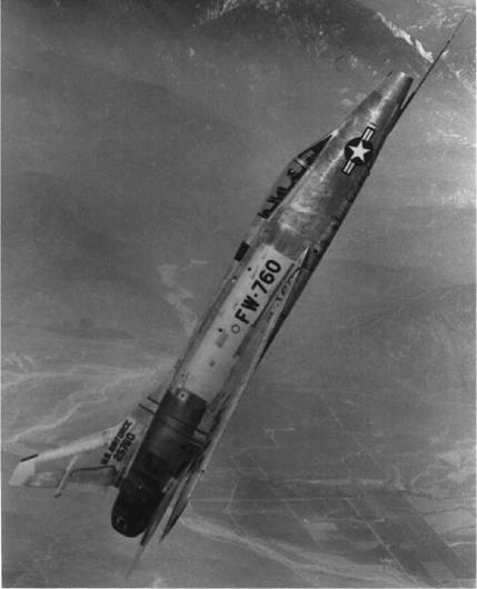
Figure 8.4 The effect of enlarging the F-100A vertical tail. The enlarged tail postpones side-slip angle divergence in rolls from roll rates of about 75 degrees per second to about 180 degrees per second, still not a very good rate. The agreement between the solid and dashed lines shows that the Schmidt-Bergrun-Merrick steady-state analysis method is a reasonably good predictive tool. The photo is of the F-100F, a late model that has the large vertical tail. (From Schmidt, Bergrun, and Merrick, WADC Conf. 56WCLC-1041, 1956)

airspeeds aeroelastic bending and torsion further reduced the fin’s contribution to directional stability.

The F-100’s inertial coupling problem illustrates a particular finding in Phillips’ 1948 analysis. Coupling is most severe when there is a large discrepancy between the levels of static longitudinal and directional stabilities, as shown by their respective natural frequen­cies. With its original small vertical tail, F-100 yaw natural frequency was particularly low. The reverse was true for the XS-1 drop model, whose flight-recorded oscillations led to the Phillips analysis. The XS-1 model had low pitch and high yaw natural frequencies at transonic speeds.

The Phillips inertial coupling charts show there is a window of stability for the case in which the natural frequencies are equal and there is some damping on each axis. Richard Heppe checked the variations of pitch and yaw natural frequencies for the Lockheed F-104 with airspeed, altitude, and loading, with discouraging results, as follows:

Maintenance of equal natural frequencies in pitch and yaw over wide speed and altitude ranges by aerodynamic means only will not be possible generally for practical airplane configurations. This implies that satisfactory roll response will become more difficult to obtain the wider the speed-altitude spectrum of the aircraft.

Thrust-Vector Control for Supermaneuvering

While supermaneuvering flight maneuvers such as the Cobra can evidently be made with ordinary aerodynamic controls, there is a growing interest in thrust vectoring for supermaneuvering (Gal-Or and Baumann, 1993). Four recent thrust-vectoring flight demonstration programs are

F/A-18 HARV (High Alpha Research Vehicle) Thrust is deflected by three vanes per engine for pitch and yaw control to a maximum angle of 12.5 degrees. Roll control is also available because of the airplane’s two engines.

X-31 Thrust is deflected for pitch and yaw control to a maximum of 15 degrees by carbon paddles, integrated with the flight control system.

F-16D MATV This airplane’s thrust-vectoring system is integrated into the engine, with maximum yaw and pitch deflection angles of 17 degrees (Figure 3.13).

YF-22 Prototype Engine nozzles are deflected in pitch at angles of attack above 12 degrees and airspeeds under 200 knots, blended with horizontal tail deflec­tions. The airplane is controllable at an angle of attack of 60 degrees (Barham, 1994).

10.4 Forebody Controls for Supermaneuvering

Alternatives to thrust-vector controls at the high angles of attack for supermaneu – vering are the blowing or strake controls that act on the vortex systems shed by tactical airplanes’ forebodies. There is an extensive literature on the effects of vortices shed by slender body noses on airplane forces and moments. The intent of blowing and strakes or

tabs is to modify these vortices for control purposes, particularly in the supermaneuvering high angle of attack regime.

Pedriero et al. (1998) demonstrated both the promise and problems of forebody blowing. Rolling and yawing moment coefficients as large as 0.02 and 0.4, respectively, are available with blowing to one side, for a cone-cylinder body with a 70-degree delta wing. However, moment linearity with jet mass flow is too poor for closed-loop control purposes. Adding controlled amounts of blowing to the opposite side improves linearity to the point where closed-loop control is possible, with no sacrifice in available control moment. In tests of forebody blowing for a model with a chine at the body’s widest point, control linearity with mass flow appears to be improved without resorting to blowing to the opposite side (Arena, Nelson, and Schiff, 1995).

The F/A-18 HARV was used to experiment with deflectable foldout strakes on the forward forebody for roll control at high angles of attack, with successful results (Chambers, 2000).

Ground Effect

The fact that the close approach of an airplane to the ground is accompanied by substantial changes in its aerodynamic characteristics has been known for some time.

This is the opening statement in an NACA report by J. W. Wetmore and L. I. Turner, Jr. (1940). Ground effect theory dates from 1922 to 1924, with work by C. Wieselsberger in

Germany and H. Glauert in Britain. The stability and control effects of the close approach of an airplane to the ground primarily are in longitudinal control and trim. A conven­tional or tail-last airplane requires more nose-up longitudinal control to hold particular angles of attack, or to stall, near the ground. Likewise, the presence of the ground in­creases the amount of nose-up control required to lift the nose wheel during takeoff ground runs.

It is interesting that the aerodynamics of an airplane model under test in a closed test section wind tunnel and that of a full-scale airplane near the ground are treated by similar theoretical methods. The solid flow boundaries caused by the wind-tunnel walls and by the ground under the airplane are represented in theory by images of the model or airplane whose downwash and sidewash flows just cancel the flow velocities that would ordinarily cross the solid boundaries.

The ground effect case is altogether simple, since a single image system does the can­cellation exactly The required image is a mirror image of the airplane, the ground itself taken as the mirror’s surface. On the other hand, for closed test section wind-tunnel walls an infinite series of images is required. Of course the most distant images are neglected for practical calculations.

The mirror image method of representing ground effect carries over into the modern application of computational aerodynamics to stability and control. That is, vortex lattice models give ground effect on longitudinal control and trim when an image vortex lattice system is added to the basic airframe lattice. This application was used in estimating ground effect for a recent tailless airplane design.

In contrast to the generally well-understood ground effect theory and mathematical mod­eling, ground effect measurements in the wind tunnel and in-flight testing are usually less than satisfactory. Low-speed wind-tunnel model tests of new designs, if they are reasonably well funded, generally include a few ground board tests. A board spanning the wind tunnel and extending some distance ahead of and behind the model is supported at a distance rep­resenting the ground. Pitch runs with ground board in place and removed give the desired ground effect increments in lift, drag, and pitching moment.

There are two main problems with ground effect wind-tunnel model tests, aside from the normal scale or Reynolds number differences between model test and the full-scale airplane. The ground board installation itself creates flow blockage in the wind tunnel, with unwanted cross-flow and buoyancy influences on the measurements. Also, a bound­ary layer stands on the ground board, starting at the leading edge of the board. There is no analog to the ground board boundary layer in real landings or takeoffs. The ground board boundary layer can be minimized by bleeds or by using a moving belt in place of the ground board. However, blockage effects must somehow be subtracted from the data.

Ground effect flight tests are equally problematic, if one wants to measure actual incre­ments in lift and control angles for trim rather than just whether the airplane has satisfactory control in the presence of the ground. The difficulty is of course maintaining stabilized flight at different angles of attack while flying with wheels inches from the ground and making measurements.

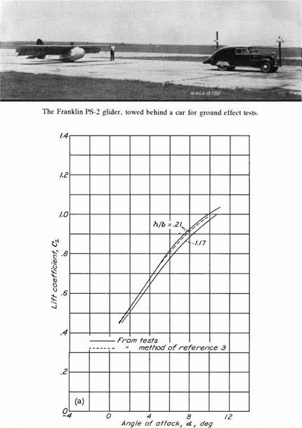
The Wetmore and Turner 1940 work that is quoted at the start of this section was a model of clever flight test design. The problem of getting stabilized flight near the ground was solved by taking ground effect measurements on a glider towed behind a car (Figure 14.7). Car buffs will enjoy the photo of NACA’s tow car. It appears to be a Chevrolet faired to resemble a Chrysler Airflow sedan. The glider pilot maintained the prescribed height above the ground by sighting targets mounted on the car.

Ground Effect

Figure 14.7 Lift coefficient versus angle of attack at two distances from the ground, as measured with a Franklin PS-2 glider towed behind a car. (From Wetmore and Turner, NACA Rept. 695, 1940)

Stabilized flight near the ground could perhaps be maintained for modern ground effect tests using autopilot loops closed around height-finding signals, such as given by radar altimeters. Likewise, NASA has a model-launching rig at Langley Field that can obtain ground effect data without wind-tunnel ground board problems. The Langley rig also sim­ulates any unsteady aerodynamic effects that may be significant. That is, real landings are dynamic affairs in that the airplane comes near the ground and lands in some time that may be short compared with the time required for stabilized flows to be established. Limited

vortex lattice calculations show that dynamic effects cause an increase in lift and pitching moment due to ground effect, as compared with steady-state conditions.

Directional Stability and Control of Canard Airplanes

Vertical tail length, or the distance from the center of gravity to the vertical tail aerodynamic center, is typically short for canards as compared with tail-aft configurations. Plan-view drawings for two Beech aircraft illustrate this (Figure 17.1). The Super King Air B200 and Starship 1 have similar gross weights (12,500 to 14,000 pounds) and have fuselage lengths of about 44 feet. The canard Starship’s vertical tail length is 18 feet; that for the tail-last King Air is 25 feet, or about 40 percent greater. The tail-last configuration would have better directional stability and control, assuming equal vertical lifting surface effectiveness for both aircraft.

Note however that the canard Starship’s vertical tails are at the wing tips. In that location, vertical tail effectiveness is not increased by fuselage end plating. The fuselage-mounted vertical tail for the King Air tail-last configuration benefits from fuselage end plating to the extent of about a 50-percent increase in lift curve slope and in effectiveness.

Lower directional stability and control levels in canard configurations can be corrected by large vertical surfaces, at the expense of higher weight and cost. The original tip-mounted vertical tails of the Rutan Vari Eze were found to be too small in NASA wind-tunnel tests (Yip, 1985). Low directional stability levels are associated with adverse yaw in rolling and poor lateral control. Low directional control power leads to control problems in takeoff and in landings in crosswinds or with asymmetric power.

According to Professor Jan Roskam of Kansas University, directional stability on the Piaggio P.180 Avanti business airplane, which has a canard surface and a relatively short vertical tail length, was improved greatly at high angles of attack with strakes located at the fuselage rear.

Spoiler Ailerons Reduce Wing Twisting in Rolls

Spoiler ailerons as a fix for wing aeroelastic twisting in rolls apparently had their first trial on a Boeing B-47. Spoiler ailerons have lower section pitching moments for a given lift change than flap-type ailerons, which means lower wing twisting moments. The proposal to use spoilers on the B-47 came from Guy Townsend, who had experience with spoilers on a Martin airplane. From an unpublished Boeing document by Cook:

In order to test them quickly, we first tried a pop-up scheme, where the several segments would fully extend in sequence as the pilot’s wheel was rotated. Electric solenoid valves at each hydraulic cylinder were programmed to open in sequence. However, this was too jerky, and proportional control was found to be required. This was later done on the B-52 mechanically.

The next step in complication was on the -80 [prototype Boeing 707], when it was decided to use the spoiler not only for roll control, but also for drag brakes in the air, and on the ground to unload the wing for better braking. This required a “mixer box.” While this system has proved reliable on 707 and subsequent models, the programming of spoilers electrically saves space and weight, and probably would provide roll control with safety by using the redundancy provided by the multiple segmented spoilers. The mechanically controlled aileron still provides a good backup for emergency [Figure 19.3].

Upper surface spoilers for lateral control, sometimes augmented by flap-type ailerons for low-speed control, are a standard feature on modern high-aspect-ratio swept-wingjets. They can be seen on a great variety of airplanes, such as the Douglas A3D-1; the Lockheed L-1011 and C-5A; the Convair 880M; the McDonnell-Douglas DC-8, DC-9, DC-10, and MD-11; the Airbus A310 and A320; and the Boeing B-52, 727, 737, 747, 757, 767, and 777 (Figure 19.4). When installed just ahead of slotted wing flaps, spoilers become slot – width control devices when the flaps are down, providing an additional bonus of powerful low-airspeed lateral control.

Aileron reversal is still a potential problem even in this modern age of supersonic air­planes and digital computers, on airplanes with straight as well as swept wings. This is indicated by the chart comparing various aileron designs for Boeing’s 2707 SST proposal. Spoiler ailerons would be needed to avoid major losses in aileron control power due to wing twist at high airspeeds, even for the 2707’s low-aspect-ratio wing (Figure 19.5).

Flying Qualities Research Moves with the Times

Robert R. Gilruth’s key flying qualities contribution was to test a significant sample of airplanes for some flight characteristic such as lateral control power and then to separate the satisfactory and unsatisfactory cases by some parameter that could be calculated in an airplane’s preliminary design stage. The Gilruth method put design for flying qualities on a rational basis, although Chapter 3 tells of some later backsliding, attempts to specify flying qualities parameters arbitrarily.

Modern times have brought the $100 million and more airplane and development costs for new prototypes into the billions of dollars. This has made for a scarcity of new machines that can be tested in the Gilruth manner and an interest in alternate flying qualities methods. The pilot-in-the-loop method surfaced around 1960 as an alternate way of rationalizing flying qualities and to focus attention on the pilot-aircraft combination as a closed-loop system. Pilot-in-the-loop analysis involves adoption of mathematical models for the human pilot as just another control system element.

The three basic concepts of the pilot-in-the-loop analysis method are (McRuer, 1973):

1. To accomplish guidance and control functions the human pilot sets up a variety of closed loops around the airplane, which, by itself, could not otherwise accomplish such tasks.

2. To be satisfactory, these closed loops must behave in a suitable fashion. As the adaptive means to accomplish this end, the pilot must make up for any dynamic deficiencies by adjustments of his own dynamic properties.

3. There is a cost to this pilot adjustment: in workload stress, in concentration of the pilot’s faculties, and in reduced potential for coping with the unexpected. The measure of the cost are pilot commentary and pilot rating, as well as physical and psychological measures.

In this chapter we trace the development of pilot-in-the-loop analysis methods as they apply to airplane flying qualities. Pilot-in-the-loop methods are clearly essential to study closed-loop operations such as tracking, but can they replace or add to the classical Gilruth approach?

Handles, Wheels, and Pedals

Before the Wright brothers demonstrated their airmanship, little thought had been given to handles, wheels, and pedals for steering flying machines. Cayley provided his reluctant coachman-aviator with an oar having cruciform bladesto “influence” the horizontal and vertical paths of his man-carrying glider. Langley provided Manley, his pilot and engine builder, with a cruciform tail that could be deflected vertically to control pitch attitude and horizontally to turn. Langley expected the dihedral angle of the tandem wings to keep them level, as they had done on his free-flying scale models.

Lilienthal shifted his weight sideways or fore-and-aft on his hang glider to control roll and pitch. This works, but it has limited effectiveness. A roll angle established by a hang glider pilot will make the machine turn if it has weathervane stability, that is, a fixed vertical tail. Hiram Maxim provided his steam-powered airplane with a gyroscopically controlled foreplane to regulate pitch attitude and thought of steering horizontally with differential power to its two independently driven pusher propellers. Fortunately he never had to try this arrangement in flight.

World War II Twin-Engine Bombers

The situation was quite different for the high-powered twin-engine bombers of World War II, such as the Martin B-26 Marauder, the Douglas A-20 Havoc and A-26 Invader, and the North American B-25 Mitchell. Loss of one engine on these airplanes, especially at low airspeeds, produced rapid and dangerous changes in yaw and sideslip, unless promptly corrected by rudder control. Remember that these airplanes were heavy, large, and fast, and that hydraulic power-assisted controls had not yet been introduced. The limiting factor in keeping these airplanes under control when an engine failed was not insufficient rudder control power but high rudder pedal force.

Rudder pedal forces to counteract engine failure on airplanes of the B-25 and B-26 class were generally aggravated by the poor design of the rudder aerodynamic balance. Suppose for example that there was a loss of power in the right engine. The airplane’s nose would quickly swing to the right, in a right yaw. Momentum would carry the airplane’s flight path along its previous direction, causing the relative wind to come from the left side. This is

a condition of left sideslip. This direction of the relative wind would cause the rudder (or rudders) to “float” or trail with its trailing edge to the right, giving right rudder.

But to regain control, left rudder would be needed, to give a left yawing moment in opposition to the thrust of the working left engine. The pilot would have to apply a large amount of left pedal force just to center the rudder from its “floated” position and then an additional amount of pedal force to get the required left rudder. The amount of left rudder required could be minimized by holding the wing with the working engine low, in a slight bank, but the net pedal force was generally the critical factor, determining the minimum airspeed at which these airplanes could be flown with one engine dead.

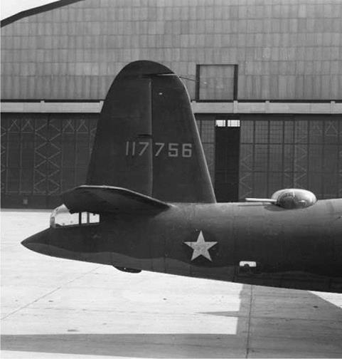
Reduction or elimination of rudder float in sideslip was available to the designers of these airplanes through tailoring of the rudder’s aerodynamic balance. Specifically, rudder horn balances would have that effect (Figure 4.2). Rudder horn balances, used as far back

World War II Twin-Engine Bombers

Figure 4.2 Experimental rudderhorn balance-fitted to the Martin B-26 Marauder. This design reduced the rudder forces required for flight after failure of one engine. It was never put into production. (From U. S. Army Air Corps photo 108769, 1942)

in aviation history as the Bleriot monoplane, were probably considered somewhat archaic to the Martin, Douglas, and North American designers. There was also a practical objection in that the projecting horns could conceivably snag parachute lines if the crew had to bail out. In any case, the A-20, A-26, B-25, and B-26 high-powered twins got through World War II without rudder horn balances.