Category Airplane Stability and Control, Second Edition

Managing Redundancy in Fly-by-Wire Control Systems

While redundancy is universally understood to be essential for safe fly-by-wire flight control systems, there are two schools of thought on how to provide and manage redundancy. Stephen Osder (1999) defines the two approaches as physical redundancy, which uses measurements from redundant elements of the system for detecting faults, and analytic redundancy, which is based on signals generated from a mathematical model of the system. Analytic redundancy (Frank, 1990) uses real-time system identification techniques, as in Chapter 14, Sec. 8, or normal optimization techniques.

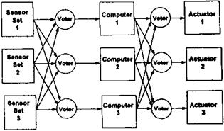
Physical redundancy is the current technology for fly-by-wire, except for isolated sub­systems. Figure 5.20 is a highly simplified diagram of a generic triplex physically redundant flight control system. The key concept is grouping of all sensors into sets and using the set outputs for each of the three redundant computers. Likewise, each of the computers feeds all three redundant actuator sets. Voting circuitry outputs the midvalue of the three inputs to the voting system. Fail-operability is provided, a necessity for fly-by-wire systems. Figure 5.20 clearly could be extended to quadruple redundant flight controls.

The practical application of physical redundancy requires close attention to communi­cations among the subsystems. Unless signals that are presented to the voting logic are perfectly synchronized in time, incorrect results will occur. In the real world, sensors, com­puters, and actuators operate at different data rates. Special communication devices are needed to provide synchronization. Additional care is required to avoid fights among the redundant channels resulting from normal error buildup, and not from the result of failures.

The situation with regard to analytic redundancy is still uncertain, since broad applica­tions to production systems have not been made. By replacing some physical or hardware redundant elements with software, some weight savings, better flexibility, and more relia­bility are promised. However, a major difficulty arises from current limitations of vehicle

Managing Redundancy in Fly-by-Wire Control Systems

Figure 5.20 Generic triplex-redundant architecture for flight-critical control systems. (From Osder, 1999)

system identification and optimization methods to largely linearized or perturbation models. If an airplane is flown into regions where aerodynamic nonlinearities and hysteresis effects are dominant, misidentification could result. Misidentification with analytic redundancy could also arise from the coupled nature of the sensor, computer, and actuator subsystems. Osder (1999) gives as an example a situation where an actuator position feedback loop opening could be misdiagnosed as a sensor failure, based on system identification.

An analytic redundancy application to reconfiguring a system with multiple actuators is given by Jiang (2000). The proposed system uses (linearized) optimization to reconfigure a prefilter that allocates control among a set of redundant actuators and to recompute feedback proportional and integral gains. A somewhat similar analytic redundancy scheme, using adaptive control techniques, is reported by Hess (2000). Baumgarten (1996) reported on reconfiguration techniques focusing on actuator failures.

The best hope for future practical applications of analytical redundancy rests in heavy investments in improved methods of system identification. This appears to be the goal of several programs at the Institute of Flight Mechanics of the DLR. Several advances at that institute and at other places are noted in Chapter 14, Sec. 8, “Flight Vehicle System Identification from Flight Test.”

5.14 Electric and Fly-by-Light Controls

Fully electrical airplane flight control systems are a possibility for the future. Elim­ination of hydraulic control system elements should increase reliability. Failure detection and correction should become a simple electronic logic function as compared with the complex hydraulic arrangement seen in the F-16’s ISA. Fly-by-light control systems, using fiber optic technology to replace electrical wires, are likewise a future possibility. Advanced hardware of this type requires no particular advances in basic stability and control theory.

Automatic Spin Recovery

The problem of recovery from oscillatory spins, where the pilot can be completely disoriented and unable to apply the proper recovery technique, suggests using suitable au­tomatic controls once a spin is recognized. A candidate technique (Lee and Nagati, 2000) suggests applying controls in a direction to cancel the vehicle’s total angular momentum vec­tor. The angular momentum vector is usually close to the angular velocity vector, differing because of unequal moments and products of inertia about body axes.

The Lee-Nagati approach is in two parts. First, the angular momentum vector is calculated several times per second during the spin. Then, at each interval, a minimization problem is solved, finding the control surface angles that minimize a cost function. The cost function is the difference between the vehicle’s momentum vector and the negative of a calculated aerodynamic control moment vector. Although not fundamental to the concept, in the Lee – Nagati paper a sophisticated regression parameter identification scheme is used to model the aerodynamic control moments used to form the control vector. One striking example of the power of this automatic control approach was a calculated recovery from a flat spin of the Grumman/American AA-1B in which a spin chute was actually used in flight.

Transonic Pitchup

Transonic high angle of attack pitchup is an instability caused by reversal of the normal, stable wing-fuselage pitching moment variation with angle of attack. In the normal, stable angle of attack range, increases in angle of attack cause negative, or nose – down, pitching moments. At high angles of attack on sweptback wings at transonic speeds flow separation on the outboard panels reverses the wing-fuselage pitching moment from negative to positive, or nose-up. The airplane will continue to rotate in a nose-up direction,

increasing the angle of attack. This can happen even against pilot application of nose-down control.

This phenomenon was first seen in flight in August 1949, on the Douglas D-558-II Skystreak research airplane being flown by Robert Champine. While pulling 4 g at a Mach number of 0.6, the airplane suddenly pitched up to 6 g. This was not much of a surprise since wind-tunnel tests had shown wing-fuselage pitching moment reversal at high angles of attack. Outer panel vortex generators delayed slightly the onset of pitchup on the D-558-II, by about 0.05 in Mach number.

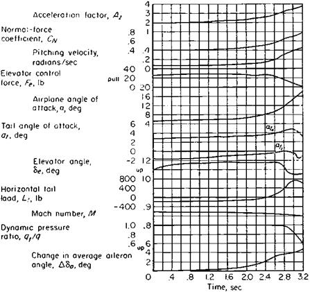
Seth B. Anderson and Richard Bray (1955) had the opportunity to analyze in detail the same transonic pitchup phenomenon as it occurred on the North American F-86 Sabre, in flight tests at Ames Aeronautical Laboratory. The key was strain gage measurements of horizontal tail load, which separate wing-fuselage instability from changes in downwash at the horizontal tail. In windup turns at a constant Mach number, load factor or g increased during the pitchup, although the tail carried an increasing, stabilizing up-load as the pitchup continued (Figure 11.13). Thus, F-86 pitchup is caused by wing instability, independently of the tail.

Transonic Pitchup

Figure 11.13 Pitchup on the North American F-86 Sabre in a turn. Normal acceleration increases after 1.5 seconds, although the elevator angle is constant or moving down. By measuring the horizontal tail load, NACA verified that the pitchup was caused by wing-fuselage instability, just as predicted in the wind-tunnel test. (From Anderson and Bray, NACA Rept. 1237, 1955)

A refinement of the Shortal-Maggin instability boundaries (Figure 11.9) was made by Joseph Weil and W. H. Gray in 1953. They showed that transonic speeds shift the bound­ary toward lower values of wing sweepback. That is, for the same wing aspect ratio, less sweepback is allowable at transonic speeds.

The Boeing B-47 has an interesting transonic pitchup case history. With a wing aspect ratio of 6.0, a quarter-chord sweepback angle of 35 degrees, and a taper ratio of 0.23, the B-47 wing falls close to the Furlong and McHugh pitchup boundary, which applies at low speeds. With the Weil-Gray shift in pitchup boundary toward less allowable wing sweep at transonic speeds, the B-47 would be expected to have transonic pitchup, and indeed it does (Cook, 1991).

As with the Douglas D-558-II, outer wing panel vortex generators reduced the pitchup instability. Vortex generators made no improvement in B-47 wind-tunnel tests, possibly because of the small scale of the generators, but Cook reports that two rows of generators actually eliminated the problem in-flight (Figure 11.14). The B-47 installation is apparently better than the one that created only a slight delay in pitchup to a higher Mach number for the D-558-II.

A design innovation of the late 1940s has made the pitchup problem relatively tractable. Where the airplane’s arrangement permits, a low horizontal tail, located below the wing chord plane extended, alleviates the problem. Wing downwash over a low horizontal tail can be counted upon to drop off, increasing tail upload and causing pitchdown, precisely when wing outer panel separation causes wing-fuselage pitchup. The influence of the vertical position of the horizontal tail was integrated into the Weil-Gray pitchup boundary in 1959 by Kenneth P Spreeman of the NACA Langley Laboratory.

The English Electric Lightning applied the low horizontal tail principle “against strong official insistence from Farnborough that the tail must be placed on top of the fin,” according to John C. Gibson. The prototype first flew in 1954. The first low horizontal tail to appear on aU. S. airplane was on the North American F-100 Super Sabre prototype a year earlier. With its high horizontal tail and low-aspect-ratio wing the Lockheed F-104 has a severe pitchup at the stall. The pilot is given a stick shaker warning of impending pitchup. A stick pusher then causes an automatic recovery. The problem of outer wing panel premature separation at transonic speeds and high angles of attack is still with designers of modern airplanes. Of course, if transonic pitchup is a problem these days, modern digitally implemented stability augmentation can correct the problem by inserting programmed countercommands or prevent it by angle of attack limitation.

The entire period when stability and control engineers grappled with the new problems brought about by flight at transonic Mach numbers is remembered by those involved as a period of great confusion and hard work. In unpublished correspondence, W. Hewitt Phillips remembers that period:

[W]ith eachnew discovery a whole generation of new airplanes appeared that solved some of the earlier problems but got into some new ones. When the dive recovery problems appeared on the fighters of World War II one of the reactions was to eliminate the tail. As a result we built the Northrop X-4 and the Vought F7U, and the British built the de Havilland DH 108. All of these airplanes were quite unsuccessful, although the Vought company got their airplane into service and gained a lot of experience on power controls.

After that came the studies of the effects of sweep and aspect ratio, and companies built planes that looked like the earlier unswept versions but with swept wings. These include airplanes like the F9F-6 and the F-84F. About this time came the discovery of notched wings, low tails, etc., and many of the pitchup problems were cured. This generation includes the F8U and the F-100.

Transonic Pitchup

Figure 11.14 Boeing B-47 wing showing the locations of the two rows of vortex generators that eliminate transonic pitchup. (From Cook, The Road to the 707, 1991)

Progress after the Guggenheim Competition

Safe personal airplane objectives have been defined as (Upson, 1942):

Progress after the Guggenheim Competition

Figure 15.1 The 1929 Curtiss Tanager, with full-span slats and flaps, demonstrating a steep climb over a 35-foot obstacle. This airplane won the Guggenheim Safe Aircraft Competition. (From Pendray, The Guggenheim Medalists, 1929—1963)

Outstanding in vision, incapable of spinning, comparable with an automobile in simplicity of control, yet with unquestioned superiority of cross-country performance.

Upson gives as examples no fewer than seven personal airplane designs that by 1942 had tried for these objectives. Which designs were viable, which were not, and what additional tries were made?

Rotary Derivatives

Rotary stability derivatives are the variations in force and moment coefficients with airplane angular velocity. Angular velocity is almost always made dimensionless in rotary derivatives by multiplication by a factor 1 /(2 V), where 1 stands for either the wing chord c or span b and V is the velocity. A typical rotary derivative is the pitch damping derivative Cmq, defined as dCm/(dqc/2V).

Rotary derivatives were neglected in the original Bryan and Williams equations of motion (Bryan and Williams, 1903), since there was then no way to measure them. However, Bryan was later able to describe two techniques for rotary derivative measurement: putting a model on a whirling table or at the end of a whirling arm, and oscillating a model in an otherwise conventional wind tunnel (Bryan, 1911).

The oscillation technique survived right up to modern times. It is used in supersonic as well as in low-speed wind tunnels. An ingenious forced oscillation technique for measuring rotary derivatives uses feedback control to stabilize the amplitude and frequency of a forced oscillation regardless of the model’s level of stable or unstable derivatives (Beam, 1956).

An additional feature of Beam’s forced oscillation method is the separation of pitch and yaw damping derivatives from the cross-rotary derivatives, such as the rolling moment due to yawing, by oscillating the model around different axes. In – and out-of-phase torque measurements are solved simultaneously for the answers. The drawback in Beam’s work is that the damping derivatives such as Cmq and Cnr are inseparable from angle of attack and side-slip rate derivatives, such as Cma and Cn^. This separation is possible in specialized forced-motion wind-tunnel tests.

One of the few wind tunnels that produced pure damping derivatives was the NACA Langley Stability Wind Tunnel. The past tense is used because the Stability Wind Tunnel was

dismantled some years ago and shipped to the Virginia Polytechnic Institute. The Stability Wind Tunnel had curved test sections in which the forces and moments on an ordinary model were the result of rotary flows. This yielded the rotary derivatives uncombined with attitude rate derivatives. The same effect was produced with curved airship models tested in ordinary wind tunnels back in the 1920s.

The Stability Wind Tunnel also used radial turning vanes ahead of the test section to produce rolling flow. Flow angularity with respect to the wind-tunnel centerline was a linear function of distance from the centerline to the tunnel walls. The aerodynamic forces on a model held rigidly at the tunnel center would be identical to those of a rolling model in an ordinary wind tunnel, except for some transverse boundary layer motion caused by radial pressure gradient. The DVL in Germany experimented with rolling flow in wind tunnels in the 1930s.

The whirling arm as a device for measuring rotary derivatives had a rebirth of sorts at the Cranfield College of Aeronautics in the early 1960s (Mulkens and Ormerod, 1993). The motivation is support of a Royal Aircraft Establishment flight research program called HIRM, for High-Incidence Research Model. Carbon-fiber-reinforced plastic, foam, and fiberglass models are whirled on an 8.3-meter arm inside a toroidal test channel. Moving the models at constant angle of attack along circular paths provides pure rotary derivative data, equivalent to that gotten from curved flow wind tunnels.

Second-Order Elastic Airplane Models

Normal mode analysis deals with linearized structural models. In particular, a non­linear coupling between rigid-body angular velocity and elastic deformations is neglected in normal mode analysis. However, this coupling shows up if one goes back to first prin­ciples in the derivation of the elastic modes by energy methods. Technically, the vector cross-product of assumed small deformations and large deformation rates is a neglected nonlinear effect. Another refinement that is neglected in ordinary normal mode analysis is the axial strain resulting from transverse deformation of the structure as a beam.

Nonlinear aeroelastic formulations that include these effects have been studied by aero­elastic investigators such as Carey S. Buttrill, Luigi Morino, R. K. Cavin, and A. R. Dusto. While nonlinear effects are conceded to be significant for the modal analysis of flexible spacecraft, the need for this sophistication is uncertain for airplanes (Buttrill, 1989).

Implications for Modern Transport Airplanes

Historically, pilot-induced oscillations (PIO) associated with fly-by-wire technol­ogy have occurred in military and experimental aircraft, which usually introduce advanced technologies before they appear on civil transports. This has provided a breathing space for that category of PIO problems to be worked out before exposing the traveling public to new hazards. However, fly-by-wire technology is now standard for new transport airplanes, bringing the possibility of PIO.

A U. S. National Research Council (NRC) report (McRuer, 1997) is intended to alert all interested parties to this hazard and to offer recommendations to avert serious problems in the future. Aside from the evident need to continue research and pilot training in this area, a few striking conclusions and recommendations emerge from the NRC report:

1. Parameters measured by on-board flight recorders, the “black boxes,” need to be at higher data rates, to capture PIO events that may have contributed to accidents. Dr. Irving Statler, who is involved in a major part of NASA’s Aviation Safety Program, states that the highest data rate found in black box recorders is only 8 samples per second, as compared with the 20-30 samples per second needed to capture PIO events.

2. Highly demanding tasks with known and suspected triggering events for PIO should be included in simulation, flight test, and certification. These tests should use pilots with experience and training in PIO events.

3. Current certification procedures should be revised to incorporate existing tech­niques for mitigating the risk of PIO.

The warnings that were sounded by the NRC report of potentially dangerous PIOs in commercial aviation should be taken seriously. The recommendations of the experienced group that wrote the report should be put into action.

On the matter of recording PIO events that may have contributed to accidents, an am­bitious approach is under study at the Aerospace Corporation and at RTCA (Grey, 2000). This is a satellite-based aircraft monitoring system and data archive that does away with the need for on-board flight recorders. The satellite-based system could provide real-time, high-data-rate information for accident prevention or diagnosis. Such a system is seen as a logical outgrowth of developments in the field of communications.

Stability and Control Textbooks and Conferences

Sharing honors with the educators in bringing stability and control theory into practice are a number of textbooks. B. Melvill Jones’ “Dynamics of the Aeroplane” section of W F. Durand’s Aerodynamic Theory (1934) is the earliest textbook with a widespread impact in the field. The second edition of Leonard Bairstow’s Applied Aerodynamics (1939) was also widely used. A truly landmark textbook appeared in 1949: Airplane Performance, Stability and Control, by Courtland D. Perkins and Robert E. Hage. This book was and still is a favorite for undergraduate stability and control instruction. It is very well balanced, giving space to many important topics. Aside from the Jones, Bairstow, and Perkins texts, we list a number of other stability and control textbooks (in English), in the order published. The pace of publishing new books in the field seems to be accelerating in recent times, with about as many new titles since 1990 as in all previous years.

W J. Duncan, Control and Stability of Aircraft. Cambridge, 1952

B. Etkin, Dynamics of Flight: Stability and Control. Wiley, 1959,1982,1985 (with L. D. Reid)

A. W. Babister, Aircraft Stability and Control. Pergamon, 1961

W. R. Kolk, Modern Flight Dynamics. Prentice-Hall, 1951

E. Seckel, Stability and Control of Airplanes and Helicopters. Academic, 1964

T. Hacker, Flight Stability and Control. Elsevier, 1970

J. Roskam, Flight Dynamics of Rigid and Elastic Airplanes. U. Kansas, 1972

B. Etkin, Dynamics of Atmospheric Flight. Wiley, 1972

D. McRuer, I. Ashkenas, and D. Graham, Aircraft Dynamics and Automatic Control. Princeton, 1973

H. Ashley, Engineering Analysis of Flight Vehicles. Dover, 1974

A. W. Babister, Aircraft Dynamic Stability and Response. Pergamon, 1980

F. O. Smetana, Computer-Assisted Analysis of Aircraft Performance, Stability and Control. McGraw-Hill, 1983

J. M. Rolfe and K. J. Staples, eds., Flight Simulation. Cambridge, 1986

R. C. Nelson, Flight Stability and Automatic Control. McGraw-Hill, 1989

J. H. Blakelock, Automatic Control of Aircraft and Missiles. Wiley, 1991

B. L. Stevens and F. L. Lewis, Aircraft Control and Simulation. Wiley, 1992

A. E. Bryson, Jr., Control of Aircraft and Spacecraft. Princeton, 1994

B. W. McCormick, Aerodynamics, Aeronautics and Flight Mechanics. Wiley, 2nd ed., 1995

G. J. Hancock, An Introduction to the Flight Dynamics of Rigid Aeroplanes. Horwood, 1995

M. B. Tischler, ed., Advances in Aircraft Flight Control. Taylor & Francis, 1996; AIAA, 2000

D. Stinton, Flying Qualities and Flight Testing of the Airplane. AIAA, 1996

J. Russell, Performance and Stability of Aircraft. Arnold, 1996

M. V Cook, Flight Dynamics Principles. Arnold, 1997

J.-L. Boiffier, The Dynamics of Flight: The Equations. Wiley, 1998

L. V. Schmidt, Introduction to Aircraft Flight Dynamics. AIAA, 1998

M. J. Abzug, Computational Flight Dynamics. AIAA, 1998

B. Pamadi, Performance, Stability, Dynamics, and Control of Airplanes. AIAA, 1998

J. Hodgkinson, Aircraft Handling Qualities. AIAA, 1999

P H. Zipfel, Modeling and Simulation of Aerospace Vehicle Dynamics. AIAA, 2000

R. W. Pratt, ed., Flight Control Systems: Practical Issues in Design and Implemen­tation. AIAA, 2000

As one of the founders of NATO’s Advisory Group for Aerospace Research and Devel­opment, or AGARD, Dr. Theodore von Karman helped greatly in the advance and dissem­ination of stability and control knowledge in the years following the second World War. In 1997, AGARD was incorporated into the Research and Technology Organization (RTO) of the Defense Research Group of NATO, as a budgetary measure.

While AGARD was still active, it brought together stability and control experts from all of the NATO countries in a wide variety of periodic meetings. For example, there were meetings of flight mechanics and guidance and control panels, symposiums, lecture series, and consultant and exchange programs. The publications and meetings of AGARD and its successor RTO remain a useful source for stability and control research and development.

In the United States, the work of the AGARD and RTO groups is paralleled by that of the Atmospheric Flight Mechanics Committee of the American Institute of Aeronautics and Astronautics, or AIAA. Under the committee’s direction, the AIAA holds valuable atmospheric flight mechanics and guidance and control conferences yearly. The Society of Automotive Engineers (SAE) has an active Aerospace Committee (formerly A-18) that briefs its members periodically and has a publication and meetings program.

In Europe, the Royal Aeronautical Society, the German Aerospace Society DGLR, and the French National Academy hold periodic conferences that address flight mechanics and control.

CHAPTER 3

Frise Ailerons

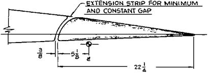
The hinge line of the Frise aileron, invented by Leslie George Frise, is always at or below the wing’s lower surface. If one sees aileron hinge brackets below the wing, chances are that one is looking at a Frise aileron (Figure 5.5). Frise ailerons were used on many historic airplanes after the first World War, including the Boeing XB-15 and B-17, the Bell P-39, the Grumman F6F-3 and TBF, and the famous World War II opponents – the Spitfire, Hurricane, and Focke-Wulf 190 fighters. Frise ailerons were applied to both the Curtiss-Wright C-46 Commando and the Douglas C-54 Skymaster during World War II, to replace the hydraulic boost systems used in their respective prototypes.

With the hinge point below the wing surface, an arc drawn from the hinge point to be tangent to the wing upper surface penetrates the wing lower surface some distance ahead of the hinge line, thus establishing an overhang balance. The gap between the aileron and wing can be made as narrow as desired by describing another arc slightly larger than the first. This in fact is typical of the Frise aileron design. The narrow wing-to-aileron gap reduces air flow from the high-pressure wing under surface to the lower pressure wing upper surface, reduc­ing drag. The Frise aileron is less prone to accumulate ice for that same reason. It was pro­moted by the U. S. Army Air Corps Handbookfor Airplane Designers asan anti-icing aileron.

The relatively sharp Frise aileron nose develops high velocities and low static pressures when projecting below the wing lower surface, when the aileron goes trailing-edge up. This generally overbalances the up-going aileron. On the other hand, the overbalanced up aileron is connected by control cables or pushrods to the down-going aileron on the other side of the wing. The sharp Frise nose on that side is within the wing contour; the down aileron is underbalanced. By connecting the up and down sides through the pilot’s controls the combination is made stable, with lowered control forces relative to ailerons without aerodynamic balance.

The sharp nose of the Frise aileron, protruding below the wing’s lower surface for trailing – edge-up deflections, has been thought to help reduce adverse yaw when rolling. The trailing – edge-up aileron is on the down-going wing in a roll. In adverse yaw, the down-going wing moves forward, while the airplane yaws in a direction opposite to that corresponding to a

Frise Ailerons

Figure 5.5 A Frise aileron design used on the Douglas SBD-1 Dauntless. This design was the seventh and final configuration tested in 1939 and 1940. Nose shape, wing-to-aileron gap, hinge line position, and gap seal parameters were all varied. (From Root, NACA W-81, 1942)

Frise Ailerons

Frise Ailerons

Figure 5.6 Flight test evidence of Frise aileron oscillations on a Waco XCG-3 glider due to alternate stalling and unstalling of the sharp nose at extreme up-aileron travels. The upper photo shows the bulky roll rate recorder. The lower photo is a rate of roll trace for two abrupt full aileron rolls. Aileron oscillations are shown by the ripples at the peak roll rate values. (From U. S. Army Air Corps photo

89368, 1942)

coordinated turn. Flow separation from the Frise aileron sharp nose is supposed to increase drag on the down-going wing, pulling it back and reducing adverse yaw. This happens to some extent, but for normal wing plan forms with aspect ratios above about 6, adverse yaw is actually dominated by the aerodynamic yawing moment due to rolling, the derivative Cnp, and is little affected by Frise ailerons. Adverse yaw must be overcome by good directional stability complemented by rudder deflection in harmony with aileron deflection.

Frise ailerons turned out to have problems on large airplanes, where there is a long cable run from the control yoke to the ailerons. In the development of the Waco XCG-3 glider in

1942, the sharp nose of its Frise ailerons alternately stalled and unstalled when the ailerons were held in a deflected position. This created severe buffeting. The aileron nose stalled at the largest angle, reducing the balancing hinge moment. Control cable stretch allowed the aileron to start back toward neutral. But as the aileron angle reduced the nose unstalled, the aerodynamic balance returned, and the aileron started back toward full deflection, complet­ing the cycle (Figure 5.6).

The fix for the XCG-3 was to limit up-aileron angles from 30 to 20 degrees and to round off the sharp nose to delay stalling of the nose. Modified Frise ailerons, with noses raised to delay stalling, had been tested in Britain by A. S. Hartshorn and F. B. Bradfield as early as 1934. The advantages of raised-nose Frise ailerons were verified in NACA tests on a Curtiss P-40 (Goranson, 1945). Beveled trailing edges were added to the raised-nose Frise ailerons on the P-40, to make up for loss in aerodynamic balance at small deflections. Lateral stick force remained fairly linear and very low up to a total (sum of up and down) aileron deflection of 48 degrees, giving a remarkably high dimensionless roll rate pb/2V of 0.138 at 200 miles per hour.

The Jets at an Awkward Age

Performance of the first jet aircraft outstripped stability and control technology. Their high performance called for two stability and control technologies that were still quite crude – power controls and electronic stability augmentation.

The high transonic Mach numbers reached by the early jets, such as the McDonnell XF-88 and the North American FJ-1, led to large and generally unpredictable control sur­face hinge moments and the possibility of control surface flutter. Redundant, irreversible hydraulic control actuators on all surfaces were really needed. With irreversible controls, the normal aerodynamically generated control stick forces would be replaced by artifi­cial forces generated by such things as springs, weights, bellows, and closed-loop force generators.

Likewise, the operating altitudes in the 30,000- and 40,000-foot range that jet power had made possible required that the normal source of damping of oscillatory yaw, pitch, and roll motions be augmented. Satisfactory damping of the Dutch roll and short-period longitudinal oscillations comes naturally near sea level from forces generated on an aircraft’s wings and tail surfaces with control surfaces fixed. However, at the higher altitudes, control surfaces need to be driven by electronic stability augmentation systems in a series fashion, added to the pilot’s inputs and not especially apparent.