Category Airplane Stability and Control, Second Edition

Bifurcation Theory

Bifurcation theory is a classical analysis method in the study of nonlinear differ­ential equations. Bifurcations are said to occur when nonlinear dynamic systems undergo changes in qualitative behavior. In bifurcation analysis, system steady states, or solutions with all time derivatives set equal to zero, and the stability about those steady states are cal­culated. The steady states are continuous functions of control surface angles. A bifurcation occurs when stability changes from one steady state to the next as a system parameter, such as control surface angle, is varied (Figure 9.12). A particular type of bifurcation known as the Hopf can lead to periodic motions such as wing rock.

A number of investigators, led initially in 1982 by J. V Carroll and R. K. Mehra, have used bifurcation theory in the study of nonlinear airplane motions, including wing rock and spins (Jahnke and Culick, 1994). P Guicheteau in France extended the wing rock application to include unsteady aerodynamic effects, and ONERA ran German-French Alpha Jet flight tests to compare with his theory. Drs. J. B. Planeaux, Jahnke, and Culick have studied bifur­cations in the United States. Also, a nonlinear analogy to linear indicial response methods has been proposed for understanding the response singularities that appear at large angles of attack and sideslip, and large rolling velocities (Tobak, Chapman, and Schiff, 1984).

Bifurcation analysis, in conjunction with piloted simulation, has been recognized as a potential aid in flight test planning (Lowenberg and Patel, 2000). This approach was experimented with using the aerodynamic and mass characteristics of the R. A.E. High Incidence Research [drop] Model, or HIRM, in bifurcation analysis and simulation in the DERA Advanced Flight Simulator, or AFS. The experimenters concluded that simulation validated the nonlinear characteristics predicted by bifurcation analysis. Thus, bifurcation analysis may be used to good effect in planning simulation and flight test programs.

The T-45A Goshawk

Thrust system dynamics reappeared as major problems many years after the Patuxent tests of the F8U and F4D-1 and the NACA, British RAE, and Systems Tech­nology studies. Two carrier-based airplanes, the McDonnell Douglas/British Aerospace T-45A Goshawk and the Lockheed S-3A Viking, had similar problems (Wilson, 1992).

As a land-based trainer, the British Aerospace Hawk has a large speed brake or airbrake under the rear of the fuselage, aft of the wings, in the so-called ventral position. Extended, the speed brake would hit the ground when landing. The Hawk’s speed brake is thus designed to retract into the fuselage automatically when the landing gear is lowered. In common with many subsonic jet airplanes, the Hawk’s jet engine is the bypass variety. Bypass jet engines provide good low-airspeed performance, with high thrust levels, and they are fuel-efficient. However, high thrust at low airspeeds means that landing approaches are normally made at idle thrust settings, or low-engine RPM. Thus, if a go-around is required, a bit more time is needed to increase RPM to maximum than for an engine without bypass.

According to George Wilson’s account, U. S. Navy test pilot Captain George J. Webb, Jr., as a carrier suitability expert, flew the original Hawk airplane in November 1983 to evaluate its behavior in simulated carrier approaches. Quoting from a draft of a memorandum from Webb to Rear Admiral E. J. Hogan, Jr., commander of the Naval Air Test Center:

Glide slope tracking [with speed brake not extended] was difficult, and corrections from high, low, and off speed conditions often resulted in numerous glide slope overshoots. Use of the ventral speed brake improved glide slope tracking and made any necessary corrections easier to accomplish.

Aircraft attitude changes associated with speed corrections were very small and difficult to discern. The combined effect made it difficult for the pilot to recognize an underpowered, decelerating situation sufficiently early to make timely corrections. Consequently, student pilots will occasionally land hard or short of the runway during syllabus flights not monitored by an LSO [Landing Signal Officer].

It was thought that the T-45A would be a straightforward conversion to naval use of a simple, existing training airplane. Thus, full-scale engineering development leading to production of 300 airplanes was launched in 1984, concurrently with U. S. Navy flight tests of the Hawk, rather than after these had been completed. Some four years later, a first interim report on the McDonnell Douglas version, the T-45A, reported that the British Hawk landing approach deficiencies spotted by Captain Webb and others had been built right into the new U. S. Navy airplane.

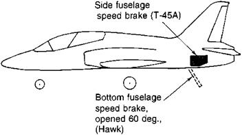
In the end, the Hawk’s single-speed brake under the fuselage, where it cannot be used in landings, was replaced on the T-45A by a pair of fuselage side brakes. These are just ahead of and under the horizontal tail (Figure 12.5). Carrier landings are made with speed brakes extended and at a high thrust level to overcome speed brake drag. At the higher thrust levels, modulation is rapid and effective in controlling the flight path. Also, just to be sure that student pilots stay out of path control trouble, the T-45A’s flight idle RPM was increased from 55 to 78 percent of maximum, by adding an approach idle stop to the throttle mechanism.

There were other changes made to the T-45A, relative to the Hawk, based on Navy flight tests. This all took place after full-scale engineering development had been started back in 1984. Hydraulically operated wing slats were added to increase wing maximum lift coefficient, a higher-thrust Rolls Royce Adour engine was installed to increase forward acceleration and reduce altitude loss when a waveoff was required, the vertical tail span

The T-45A Goshawk

Figure 12.5 Path control problems for carrier landings required changes to the McDonnell-Douglas T-45A Goshawk. Speed brakes were moved from the bottom to the side of the fuselage. (From Jane’s AH the World’s Aircraft)

was increased, and a yaw damper and rudder-to-aileron interconnect was added to improve lateral-directional (Dutch roll) behavior. Captain Webb had complained about this following his Hawk flights in 1983.

Also, bearing specifically on the thrust lag problem during carrier-landing operations, the Navy installed modified Lucas fuel controls on the T-45A’s Adour engines, to minimize thrust lag when power increases are called for. Finally, the speed brakes are interconnected to the horizontal stabilizer to minimize trim changes when the brakes are extended or retracted.

Single-Pilot IFR Operations

Making landing approaches completely by instrument is a demanding piloting procedure. Pilots are given the instrument rating only after many hours of ground school, practice in flight, and rigorous ground and flight examinations. In the United States, non­airline instrument-rated pilots must renew their ratings every six months, either by an instrument competency check ride with a flight instructor or by having flown six hours under the hood or in instrument weather conditions, and also having made six instrument approaches in that time period.

Pilots of commercial airliners get a great deal more instrument flying practice than do private instrument-rated pilots. Private instrument-rated pilots must have a minimum of only six hours of blind-flying time and six instrument approaches every six months in order to remain current. Commercial airline pilots get frequent instrument flying practice because, by law, all airplanes operating above an altitude of 18,000 feet must be on an instrument flight plan. Also, jet air carriers have agreed with the FAA to fly under instrument flight plans when below 10,000 feet, although this is not required by law.

This attention to training is not misplaced, when one understands the cockpit environ­ment in a personal airplane during an instrument approach in bad weather. The pilot has to cope with instrument readings of heading, lateral position, velocity, vertical position, and rate of sink, as a minimum. The pilot or pilots must also handle radioed instructions or advisories on headings, intersection crossing altitudes, radio frequency changes, traffic (other aircraft), wind, and airport runway conditions. Instructions, over a frequently busy and static-corrupted radio, must be repeated and copied on a knee pad as a backup to memory, since uplinked and displayed instructions are still in the future. Approach plates and landing checklists must be consulted under often poor lighting. Added to all of these may be concerns over icing conditions and fuel reserves.

By the time of NASA’s second flight test series on personal-airplane flying qualities, in 1966, personal airplanes were being used for precision ILS instrument approaches, often with a single pilot. It was and still is reasonable to ask whether the poor Dutch roll and phugoid damping, excessive longitudinal trim changes due to power application, and the badly designed trim systems found in the 1966 NASA tests add significantly to the single­pilot instrument approach problem.

Pilot workload studies in connection with instrument approaches began almost as soon as the procedures themselves. However, the few studies that examine the correlation between flying qualities and single-pilot instrument approach capability have not gone far enough. For example, a variable-stability airplane test at Princeton University used a single, expe­rienced pilot, subjected to artificial distractions (Bar-Gill and Stengel, 1986). Only mild correlations were found between glide slope and airspeed errors and some stability and trim change parameters.

However, one would really like to know whether poor flying qualities can play a role in deteriorating a single-pilot instrument approach under more severe conditions and with less capable but instrument-rated pilots. Single-pilot instrument approaches under stressful conditions have ended in disaster many times, and we usually have no way of knowing what contribution was made by specific flying qualities.

Equations of Motion Extension to Suborbital Flight

Suborbital flight is flight within the atmosphere but at extremely high altitudes. In this regime, flight speeds are very high, and the curving of constant-altitude flighttrajectories around the earth’s surface adds appreciable centrifugal force to wing lift. Bryan’s equations

of rigid-body motion are for flight over a flat earth. Flat-earth equations of motion generally are inadequate for airplanes that operate in a suborbital mode.

A derivation of nonlinear airplane equations of motion for the spherical-earth case can be found in Etkin (1972). The main distinction between the spherical – or oblate-earth cases and the classical Bryan flat-earth equations lies in additional kinematic (nondifferential) equations. As in the ordinary flat-earth equations, 12 state equations must be integrated. In the Etkin approach, linear accelerations are integrated in airplane body axes, producing the usual inertial velocity and angle of attack and sideslip variables. However, this is only one of several possible choices for the linear accelerations. The angular acceleration equations of motion are integrated in airplane body axes, as for the flat-earth case. This is the only practical choice, since airplane moments and products of inertia are constant only in body axes.

Full nonlinear equations of airplane motion about a spherical or oblate rotating earth were produced somewhat later at Rockwell International in connection with the Space Shuttle Orbiter and still later for studies of the National Aerospace Plane (NASP). The earliest set is found in Rockwell Report SD78-SH-0070, whose authors we have been unable to identify. Six distinct reference axes systems are used. The Rockwell set integrates linear accelerations and velocities in an earth-centered inertial axis system, making transformations to the other axes, such as the body and airport reference sets.

Still another approach was followed at the NASA Dryden Flight Research Center (Powers and Schilling, 1980, 1985) for the Space Shuttle Orbiter, in order to build on an earlier flat-earth 6-DOF computer model. A heading coordinate frame is centered at the orbiter’s center of gravity, with the Z-axis pointed to the earth’s center and the X-axis aligned with the direction of motion. X and Z define the orbit plane through the geocenter. Linear accelerations and velocities are integrated in heading coordinate and earth axes frames, respectively Vehicle vertical and horizontal velocities in the orbit plane and body axis heading relative to the orbit plane replace the ordinary body axis velocity coordinates in the airplane’s state vector. Altitude above a reference sphere of equatorial radius, latitude, and longitude replace the ordinary altitude, downrange and cross-range position coordinates in the airplane’s state vector. High precision data, such as FORTRAN double precision with 15 significant figures, are needed.

Attitude deviations from the Rockwell/Dryden heading coordinate frame produce Euler angles in the classical sense: yaw, then pitch, then roll. Use of this particular heading coordinate system also for space or re-entry vehicles would produce a consistent set of aerospace flight mechanics axes, which would seem to be an advantage.

The oblate earth version of the equations of airplane motion is sometimes used even when there is no question of hypersonic or suborbital flight operations. This is in flight simulators when one wishes to have only one set of airplane equations for both flying qualities and long-range navigation studies. A single, unified airplane mathematical model for both purposes avoids duplication of costly manned flight simulators and the problem of keeping current two different data bases during airplane development. For simulated flights lasting on the order of hours, correct latitude and longitude coordinates can be calculated as inputs to flight data computers.

The almost incredible capacity of modern digital computers makes it feasible to expend computing capacity by including high-frequency airplane dynamics terms in the flight simulation of an hours-long navigational mission, as compared with spending engineering time to develop a special simulation without the high-frequency terms. This was the route chosen for the Northrop B-2, according to our best information.

20.9.1 Roll-Ratcheting

Roll-ratcheting bears a resemblance to the aileron buffeting that occurs on sharp­nosed Frise ailerons. The limit cycle oscillations occur at about 3 cycles per second when the ailerons are hard over, and the flight records even look the same (compare Figure 20.4 with Figure 5.6). However, the two phenomena could hardly be more different.

Roll-ratcheting arises from interactions among a variety of mechanisms. These include arm neuromuscular effects, limb and stick mass effective stick bobweights, force-sensing side stick gains, and roll command prefiltering. At 2 to 3 cycles per second, pilot voluntary efforts are not involved, so that roll-ratcheting is not a form of the pilot-induced oscillations discussed in Chapter 21.

A major effort was made to pin down roll-ratcheting parameters, using a fixed based simulator (Johnston and McRuer, 1977). The progress of that investigation, which brought in flight test data from the NT-33 variable-stability research airplane as well as the F-16, is given in fascinating detail by Irving L. Ashkenas in a summary paper (1988). There is a convincing correlation involving the stick sensing force gradient (degrees per second of roll rate per pound of stick force) and roll time constant TR, in seconds. A single line divides roll command augmentation systems into ratcheting and nonratcheting cases. However, this particular correlation is thought to hold only for nonmoving or force-type side sticks, such as installed in the F-16 airplane.

The role of arm neuromuscular effects as a prime component of roll-ratcheting is ques­tioned by Gibson (1999). In Delft TU studies, a simple assumption of a lateral bobweight

loop was found to produce roll-ratcheting. A later paper from DVL, Braunschweig (Koehler, 1999) returns to the neuromuscular model with refinements, adding torso and hip dynamics to that of the arm. The Koehler paper claimsgood correlation with an F-16 XL roll-ratcheting incident. Gibson notes that a spectacular roll-racheting incident involving the F-18 is de­scribed by Klyde (1995). A mild rachet occurred on the BAe FBW (fly-by-wire) Jaguar airplane, which was cured by adding a stick damper and by changes to high-frequency control dynamics.

A prudent design approach to avoid roll-ratcheting might be to adhere initially to the Ashkenas 1988 force gradient/roll time constant criterion, supplementing this with detailed stability analyses that account for both neuromuscular and bobweight effects.

Large Airplanes with Reduced-Static Longitudinal Stability

In a paper on stability augmentation for a large, flexible airplane that appears to be the Boeing 777, Greta Ward (1996) makes an interesting observation on the limitations of reduced-static longitudinal stability when applied to large airplanes. Reduced-static lon­gitudinal stability is an attractive feature for long-range airplanes, reducing cruise flight trim drag and fuel consumption. In any such application, a designer must retain a suitable margin of longitudinal control power to recover from inadvertent upsets, upsets that would be opposed by static stability in airplanes of normal longitudinal stability.

Pitch moment of inertia varies as the fifth power of fuselage length, while the maximum available pitching moment produced by a horizontal tail surface varies only as the third power of fuselage length. This implies an upper limit to fuselage length and airplane size if reduced-static longitudinal stability is to be used.

23.2 Large Supersonic Airplanes

A successor to the supersonic Concorde is likely to be a large airplane, in the sense considered here. The stability and control problems of supersonic flight and low-speed flight of a low-aspect-ratio design would be added to those of large airplanes. A general review of the combined problems (Steer and Cook, 1999) reflects experience with the Concorde. The authors conclude that a foreplane, or canard surface, would be needed in place of the tailplane used in the Boeing/NASA High-Speed Commercial Transport (HCST) design.

Variable-Stability Airplanes as Trainers

The objectives of most of the variable-stability programs were either to apply the Gilruth method of obtaining flying qualities requirements by exposing pilots to different stability and control levels or to present the flying characteristics of a future machine for evaluation. However, quite by chance, a different use for variable-stability airplanes cropped up. Breuhaus reports that Gifford Bull, the project engineer and safety pilot of a Calspan variable-stability USAF B-26 airplane, was chatting with members of the Navy Test Pilot School at the Patuxent River Naval Air Test Center. The B-26 was at Patuxent to run Navy-sponsored tests on minimum flyable longitudinal handling qualities under emergency conditions. Test Pilot School staffers were struck by what looked like

the unique suitability of the variable stability airplane to serve as a flying class room or laboratory to demonstrate to the school the effects of the myriad flying quality conditions that could be easily and rapidly set up.

A trial run in 1960 was such an instant success that the program was broadened to include the Air Force Test Pilot School at Edwards Air Force Base, and a second B-26 was added. The aging B-26s were eventually replaced by two variable-stability Learjet Model 24s. By the end of 1989 nearly 4,000 service, industrial, and FAA pilots and engineers had instruction or demonstrations using the variable-stability B-26s and Learjets.

In a more recent application of an airplane modified to fly like another airplane for training, NASA used a Grumman Gulfstream G-2 in a high drag configuration to train pilots to fly the Space Shuttle’s steep, fast-landing approach profile, starting at an altitude of about 30,000 feet.

Spring Tabs

Spring tabs overcome the main problem of flying tabs, which do not provide the pilot with control of the main surface at low speeds, as when taxiing. In spring tabs, the pilot’s linkage to the tab is also connected to the main surface through a spring. If the spring is quite stiff, good low-speed surface control results. At the same time, a portion of the pilot’s efforts goes into moving the main surface, increasing controller forces.

Spring tabs have the useful feature of decreasing control forces at high airspeeds, where control forces usually are too heavy, more than at low airspeeds. At low airspeeds, the spring that puts pilot effort into moving the main surface is stiff relative to the aerodynamic forces on the surface; the tab hardly deflects. The reverse happens at high airspeeds. At high airspeeds the spring that puts pilot effort into moving the main surface is relatively weak compared with aerodynamic forces. The spring gives under pilot load; the main surface moves little, but the spring gives, deflecting the tab, which moves the main surface without requiring pilot effort.

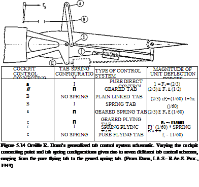
The earliest published references to spring tabs appeared as Royal Aircraft Establishment publications (Brown, 1941; Gates, 1941). NACA publications followed (Greenberg, 1944; Phillips, 1944). But the credit for devising a generalized control tab model that covers all possible variations (Figure 5.14) belongs to Orville R. Dunn (1949). The Dunn model uses three basic parameters to characterize spring tab variations, which include the geared tab, the flying tab, the linked tab, and the geared spring tab.

Although the derivation of pilot controller force equations for the different tab systems involve only statics and the virtual work principle, the manipulations required are surpris­ingly complex. As is typical for engineering papers prepared for publication, Dunn provides only bare outlines of equation derivations. Readers of the 1949 Dunn paper who want to derive his final equations should be prepared for some hard labor.

Dunn concluded that spring tabs can produce satisfactory pilot forces on subsonic transport-type airplanes weighing up to several million pounds. At the time of Dunn’s paper, spring tabs had indeed been used successfully on the Hawker Tempest, the Vultee Vengeance rudder, all axes of the Canberra, the rudder and elevator of the Curtiss C-46 Com­mando, the Republic XF-12, and the very large Convair B-36 bomber. They also would be used later on the Boeing B-52 Stratofortress. Dunn’s account of the DC-6 development tells of rapid, almost overnight, linkage adjustments during flight testing. The major concerns in spring tab applications are careful design and maintenance to minimize control system static friction and looseness in the linkages.

The B-19 experience encouraged Douglas engineers to use spring tabs for many years afterwards. Both the large C-124 and C-133 military transports were so equipped. The

Spring Tabs

DC-6, -7, -8, and -9 commercial transports all have some form of spring tab controls, the DC-8 on the elevator and the DC-9 on all main surfaces, right up to the latest MD-90 version. In that case, the switch was made to a powered elevator to avoid increasing horizontal tail size to accommodate the airplane’s stretch. A powered elevator avoids tab losses and effective tail area reductions because tabs move in opposition to elevator travel.

The Douglas DC-8 and -9 elevator control tabs are actually linked tabs, in which pilot effort is shared between the tab and the elevator. This gives the pilot control over the elevator when on the ground. The DC-8 and -9 elevator linked tabs are inboard and rather small. The inboard linked tabs are augmented by outboard geared tabs, which increase the flutter margin over single large linked tabs. The DC-9 elevator controls are hybrid in that hydraulic power comes in when the link tab’s deflection exceeds 10 degrees. Spring tabs serve a backup purpose on the fully powered DC-8 ailerons and rudder and on the DC-9 rudder. The tabs are unlocked automatically and used for control when hydraulic system pressure fails. The same tab backup system is used for the Boeing 727 elevator.

The spring tab design for the elevators of the Curtiss C-46 Commando was interesting for an ingenious linkage designed by Harold Otto Wendt. Elevator surfaces must be statically balanced about their hinge lines to avoid control surface flutter. Spring tabs should also be statically balanced about their own hinge lines. Spring tab balance weights and the spring mechanisms add to the elevator’s weight unbalance about its hinge line. Wendt’s C-46 spring tab linkage was designed to be largely ahead of the elevator hinge line, minimizing the amount of lead balance required to statically balance the elevator.

Spring tabs appear to be almost a lost art in today’s design rooms. Most large airplanes have hydraulic systems for landing gear retraction and other uses, so that hydraulically operated flight controls do not require the introduction of hydraulic subsystems. Further­more, modern hydraulic control surface actuators are quite reliable. Although spring tab design requires manipulation of only three basic parameters, designing spring tabs for a new airplane entails much more work for the stability and control engineer than specifying

parameters for hydraulic controls. Computer-aided design may provide spring tabs with a new future on airplanes that do not really need hydraulically powered controls.

The 1956 Wright Field Conference

When inertial coupling first appeared on the scene with the Douglas X-3 research airplane and then the F-100A Super Sabre, interest in the subject grew quickly among those responsible for fighter airplane stability and control. Although first-line fighter flight test results were classified either confidential or secret, the grapevine was hard at work, and information started to circulate on this new potential for uncontrolled maneuvers and structural failures.

U. S. Air Force and Naval engineerssaw the need for groupsgrappling with the unexpected inertial coupling problem to convene and exchange information for the common good. A closed-door, classified conference was therefore called at Wright Field for February 1956. Papers were invited from industry, NACA, and MIT. Because of the urgency and national importance of the subject, authors and attendees from industry were expected to give open accounts of their results, putting aside competitive considerations.

The list of speakers at the since-declassified Wright Field Conference, formally called “Wright Air Development Center Conference on Inertia Coupling of Aircraft,” included many of the important stability and control researchers and designers of fighter aircraft of that period:

They were: Robert Bratt and Charles DaRos of Douglas; Frederick Curtis, Mamoree Masaki, and Dewey Mancuso of Convair; John Gautraud, James Flanders, Thomas Parsons, and Lloyd Wilkie of MIT; Richard Heppe of Lockheed; Wayne Huff and Cecil Carter of Chance Vought; Henry Kelley, Hans Hinz, and Robert Kress of Grumman; Darrel Parke of McDonnell; Jerry Pavelka of Republic; Stanley Schmidt, Norman Bergrun, Robert Merrick, Leonard Sternfield, Joseph Weil, and Richard Day of NACA; and John Wykes of North American.

Charles Westbrook chaired the conference and edited the proceedings (Westbrook, 1956). The lively interest in inertial coupling brought no fewer than 184 conference attendees. This conference on a serious stability problem held in the halls of their chief customer brought out

The 1956 Wright Field Conference

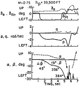
Figure 8.5 Time history of a classic inertial coupling example. The YF-102 diverges to a negative angle of attack and left (negative) side-slip angle in a rapid roll. (From Weil, WADC Conf. 56WCLC-1041, 1956)

a certain defensiveness in the speakers from industry. No blanket criticism is now intended, since it is understandable that airplane designers should want to put their products in the best light. Still, the transcript shows statements such as these:

In all of these [roll] tests the airplane response has been normal to the pilot and safe from every flight standpoint.

… serious difficulty due to inertial coupling is not to be anticipated for the——— .

…. the generally satisfactory roll behavior of the airplane was most welcome….

These benign, reassuring words were accompanied by hair-raising simulation and flight records, in several cases, such as the Convair YF-102 (Figure 8.5).

Longitudinal Control for Recovery

Tactical airplanes are able to reach supermaneuvering angles of attack by low or even negative static longitudinal stability. Full nose-up control starts the pitchup; unstable or nose-up pitching moment keeps it going. Recovery requires a nose-down pitching moment that will overcome the unstable pitching moment and leave a margin for nose-downward angular acceleration.

A rule of thumb for recovery nose-down pitching moment has been proposed, based on simulation studies and practical fighter design (Mangold, 1991). A pitching acceleration of 0.3 radians per second squared is said to be adequate. This leaves a margin for inertial coupling due to rolling during the pitching maneuver. A related problem is the amount of longitudinal control power required for very unstable airplanes, not necessarily during su­permaneuvers. For that problem, Mangold correlates required pitching acceleration control with time to double amplitude.

The recovery control problem also has been attacked using the classical Gilruth approach (Nguyen and Foster, 1990). Satisfactory and unsatisfactory recovery flight characteristics are used to draw a criterion line in a plot of minimum available pitching moment coefficients with full-down control versus a moment of inertia and airplane size parameter. With only five flight data points, Nguyen and Foster call their criterion preliminary.

10.5 Concluding Remarks

Current tactical airplane maneuverability research spans all aspects of the stability and control field, from linearized transfer functions to unsteady aerodynamics and the complex, vortex-imbedded flows found at very high angles of attack. Further advances and new theories appear likely with the advent of thrust-vectoring and direct side and normal force control.

CHAPTER 11