Category Airplane Stability and Control, Second Edition

Stability Boundaries

Until the advent of electronic analog and digital computers, numerical solutions of the equations of airplane motion were essentially limited to finding stability boundaries, the combinations of airplane stability derivatives and other parameters that divide stability from instability. Stability boundaries are found by Routh’s Criterion, developed by the Briton E. J. Routh in the early 1900s.

Airplane stability boundaries were first calculated in Britain (Bryant, Jones, and Pawsey, 1932). This was in a study of dynamic stability beyond the stall. Bryant and his co-authors found stability derivatives for a number of airplanes up to an angle of attack of 40 degrees. With these data, they produced stability boundaries as functions of static directional and lateral stability derivatives, both nondimensionalized by Glauert’s airplane relative density parameter /г.

There was an earlier British paper by S. B. Gates that presented contours of constant damping ratio and natural frequency for the longitudinal phugoid, as functions of tail volume and center-of-gravity position (Gates, 1927). While not strictly a stability boundary analysis, the Gates work certainly laid the groundwork for Bryant’s boundaries.

Two NACA reports by Charles H. Zimmerman (1935 and 1937) carried on Gates’ and Bryant’s pioneering stability boundary work. Zimmerman’s ambitious goal was to produce charts for the rapid estimation of the dynamics of any airplane. The Zimmerman reports have charts for both longitudinal and lateral motions, 40 of the former and 22 of the latter (Figure 18.6). As in Bryant’s work, the results are normalized using Glauert’s airplane density parameter г. The Zimmerman charts include period and damping estimates for the phugoid and Dutch roll motions.

Stability Augmentation

Stability augmentation is the artificial improvement, generally by electromechani­cal feedback systems, of airplane stability and control while the airplane remains under the control of the human pilot. Stability augmentation generally changes the airplane’s stability derivatives and modes of motion.

We make the important distinction between stability augmentation, artificial feel systems, and airplane automatic pilots. While artificial feel systems, discussed in Chapter 5, may alter stick-free stability for the better, their main function is providing manageable control forces. Automatic pilots replace the human pilot when they are in use.

20.1 The Essence of Stability Augmentation

To be a true stability augmenter, the device must change the airplane’s flight characteristics without the pilot’s perception. This means that augmenter outputs must add to those of the pilot in a series fashion. Augmenter outputs put into the primary control circuit between the cockpit and the control surfaces must move only the control surfaces, and not the cockpit controls. The requirement to not move the pilot’s controls is sidestepped if the augmenter is not inserted into the primary control circuit but moves a separate, or dedicated, control surface. Still another way around the need for augmenters not to move the pilot’s controls is the integrated control surface actuator (Chapter 5), used in fly-by­wire control systems. Integrated servo actuators accept and add electrical signals from both cockpit controls and stability augmenters.

In fly-by-cable control systems, isolation of primary-control-circuit stability augmenter outputs from the cockpit controls is a surprisingly difficult mechanical design problem. Control valve friction in control surface actuators acts to hold the surfaces fixed for small stability augmenter signals. When this happens, the augmenter in effect backs up and moves the cockpit controls instead. The result is an unaugmented airplane for small disturbances and limit cycle oscillations, such as yaw snaking. One cure for excessive valve friction can be as bad as the small signal backup problem. This is to center the cockpit controls with husky spring detents, which have to be overcome by the pilot in normal control use.

The degree of authority of stability augmentation systems is another important design consideration. Since augmenters operate ideally without moving the pilot’s controls, the pilot will be unaware of abrupt failures to the limit of augmenter authority until the airplane reacts. Then, there should be enough pilot control authority left to add to and cancel the failed augmenter inputs, with something to spare. This was the design philosophy until the advent of redundant, self-correcting augmentation systems, which make feasible augmentation at full authority or control surface travel.

Automatic pilots, which replace the human pilot when they are in use, are expected to move the cockpit controls. Abrupt full autopilot failures are instantly apparent to an attentive flight crew. Larger control authority than for stability augmenters is feasible, even for systems without the redundant, self-correcting feature.

Challenge of Stealth Aerodynamics

The invention of aircraft that are almost invisible to ground or surface-to-air – missile radars promises to be an effective defensive measure for reconnaissance and attack airplanes. This development has taken six paths so far, the first three of which are a distinct challenge to stability and control designers:

Faceted airframes replace the smooth aerodynamic shapes that produce at­tached flows and linear aerodynamics. Radar returns from faceted shapes, such as the Lockheed F-117A, are absent except for the instants when a facet faces the radar transmitter.

Parallel-line planforms have the same sweep angle on wing leading and trailing edges and on surface tips and sharp edges. Parallel-line planforms concentrate radar returns into narrow zones that are easily missed by search radars. This is the Northrop B-2 stealth method, augmented by special materials and buried engines.

Suppressed vertical tails are either shielded from radar by wing structure or eliminated altogether. The Lockheed F-22 has shielded vertical tails, the B-2 none at all.

Blended aerodynamics eliminate internal corners such as wing-fuselage inter­sections. Internal corners can act as radar corner reflectors. The Rockwell B-1 uses this technique to reduce its radar signature.

Buried engines and exhausts hide compressor fan blades and hot exhaust pipes from radar and infrared seekers.

Radar-absorbent materials are used, generally nonmetallic. This is a highly classified subject.

The challenges of faceted airframes, parallel-line planforms, and suppressed vertical tails to stability and control engineers are illustrated by current stealth airplanes.

Flying Qualities Become a Science

The stability and controllability of airplanes as they appear to a pilot are called flying or handling qualities. It was many years after airplanes first flew that individual flying qualities were identified and ranked as either desirable or unsatisfactory. Even more time passed before engineers had design methods connected with specific flying qualities. A detailed and fascinating account of the early work in this area is given in Chapter 3 of Stanford University Professor Walter G. Vincenti’s scholarly book What Engineers Know and How They Know It. We pick up the story in 1919, with the first important step in the process that made a science out of airplane flying qualities.

3.1 Warner, Norton, and Allen

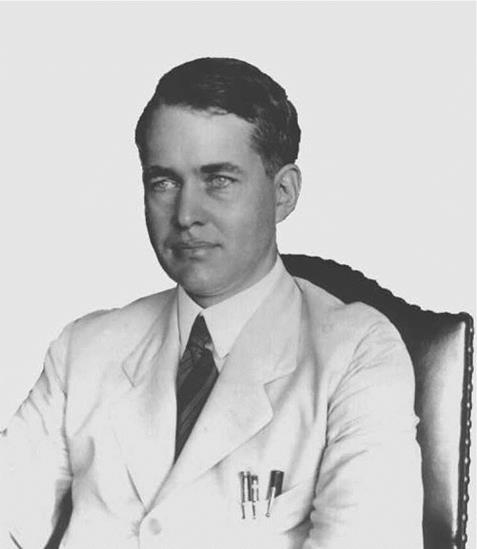
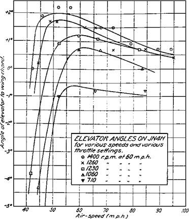
Vincenti found that the first quantitative stability and control flight tests in the United States occurred in the summer of 1919. MIT Professor Edward P Warner (Figure 3.1), working part time at the NACA Langley Laboratory, together with two NACA employees, Frederick H. Norton and Edmund T Allen, made these tests using Curtiss JN-4H “Jennies” and a de Havilland DH-4. They made the most fundamental of all stability and control measurements: elevator angle (with respect to the fixed part of the tail, or stabilizer) and stick force required for equilibrium flight as a function of airspeed.

Warner and Norton made the key finding that the gradient of equilibrium elevator angle with respect to airspeed was in fact an index of static longitudinal stability, the tendency of an airplane to return to equilibrium angle of attack and airspeed when disturbed. The eleva­tor angle-airspeed gradient thus could be correlated with the 1915-1916 MIT wind-tunnel measurements by Dr. Jerome C. Hunsaker of pitching moment versus angle of attack on the Curtiss JN-2, an airplane similar to the JN-4H. In the words of Warner and Norton (1920):

If an airplane which is flying with the control locked at a speed corresponding to the negatively sloped portion of the elevator position curve is struck by a gust which decreases its angle of attack, the angle will continue to decrease without limit. If the speed is low enough to lie on the positively sloping portion of the curve, the airplane will return to its original speed and angle of trim as soon as the effect of the gust has passed. A positive slope [of the elevator angle-airspeed gradient] therefore makes for longitudinal stability. (Italics added)

A strange aspect of the Warner and Norton JN-4H test results was the effect of airspeed on static longitudinal stability. The JN-4H was stable at airspeeds below about 55 miles per hour and unstable above that speed (Figure 3.2). One would be tempted to look for an aeroelastic cause for this, except that wind-tunnel tests of a presumably rigid model showed the same trend. The cause remains a mystery. The 1915-1916 MIT wind-tunnel tests were supplemented in 1918 by the U. S. Air Service at McCook Field with JN-2 wind-tunnel tests, in which the model had an adjustable elevator angle.

The McCook Field group was active in stability and control flight tests at the same period. As part of an armed service procurement activity, McCook’s primary interest was in airplane

Flying Qualities Become a Science

Figure 3.1 Edward Pearson Warner (1894-1958). His DC-4E flying qualities requirements launched a new science. (From National Air and Space Museum)

suitability for military use, rather than in aeronautical research. Thus, it is understandable that there were no measurements at the level of sophistication of the Norton and Allen tests at the NACA. Captain R. W. (Shorty) Schroeder was one of the Air Service’s top test pilots. His 1918 (classified Secret) report on the Packard-Le Pere LUSAC-11 fighter airplane’s handling qualities was completely qualitative.

In the course of the pioneering stability and control flight tests at the NACA Langley Laboratory, instrumentation engineers including Henry J. E. Reid, a future Engineer-in­Charge at Langley, came up with specialized devices that could record airplane motions automatically, freeing pilots from having to jot down data while running stability and control flight tests. Langley Laboratory individual recording instruments developed in the 1920s measure control positions, linear accelerations, airspeed, and angular velocities.

Flying Qualities Become a Science

Figure 3.2 Warner and Norton’s measurements of elevator angles required to trim as a function of airspeed and power for the Curtiss JN4H (Jenny) airplane. They correctly interpreted the data to show static longitudinal instability at airspeeds above the peaks of the curves. (From NACA Rept. 70, 1920)

In each recording instrument, a galvanometer-type mirror on a torsion member reflects light onto a photographic film on a drum. A synchronizing device keys together the record­ings of individual instruments, putting timing marks on each drum. Frederick Norton said in later years that the work at Langley in which he took the most pride was the development of these specialized flight recording instruments (Hansen, 1987).

The instrument developments put NACA far in front of other groups in the United States who were working on airplane stability and control. The photorecorder was typical technology at other groups running stability and control tests, such as the U. S. Army Air Corps Aircraft Laboratory at Wright Field. In the photorecorder, stability measurement transducers, ordinary flight instruments, and a stopwatch are mounted in a bulky closed box and photographed by a movie camera. Data are then plotted point by point by unfortunate technicians or engineers reading the film.

As another indication of NACA’s advanced flying qualities measurement technology, one of this book’s authors (Abzug) who served in the U. S. Navy during World War II remembers having to borrow a stick force measuring grip from NACA to run an aileron roll test on a North American SNJ trainer.

NACA flying qualities research in the 1920s and early 1930s also trained a group of test pilots, including Melvin N. Gough, William H. McAvoy, Edmund Allen, and Thomas

Carroll, in stability and control research techniques, including the ability to reach and hold equilibrium flight conditions with accuracy As with all good research test pilots, the NACA group worked closely with flight test engineers and in fact took part in discussing NACA’s flying qualities work with outsiders. All of this helped lay the groundwork for the comprehensive flying qualities research that followed.

Aileron Differential

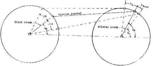
The larger travel of one aileron relative to the other is called aileron differential (Figure 5.7). Aileron differential is a method of reducing control forces by taking advantage of hinge moment bias in one direction (Jones and Nerkin, 1936; Gates, 1940). At positive wing angles of attack, the hinge moment acting on both ailerons is normally trailing-edge – up, and we say the ailerons want to float up. Assume that the up-going aileron is given a larger travel than the down-going aileron for a given control stick or wheel throw. Then, the work done by the trailing-edge-up hinge moment acting on the up-going aileron can be nearly as great as the work the pilot does in moving the down-going aileron against its up-acting hinge moment, and little pilot force is needed to move the combination. The differential appropriate for up-float is more trailing-edge-up angle than down. Typical values are 30 degrees up and 15 degrees down. The floating hinge moment can be augmented, or even reversed, by fixed tabs.

Aileron Differential

Figure 5.7 The principle of aileron differential, or unsymmetrical up and down travels. Stick crank motions A& of the same amount on each wing cause larger up-aileron deflections Su than down-aileron deflections Sdmax. (From Jones and Nerkin, NACA TN 586, 1936)

Aileron up-float, associated with negative values of the hinge moment derivative Cha, is greatest at high wing angles of attack. Neglecting accelerated flight, high wing angles of attack occur at low airspeeds. Thus, aileron differential has the unfortunate effect of reduc­ing aileron control forces at low airspeeds more than at high airspeeds, where reductions are really needed. In addition to the force-lightening characteristic of aileron differential, increased up relative to down aileron tends to minimize adverse yaw in aileron rolls, which is the tendency of the nose to swing initially in the opposite direction to the commanded roll.

Adverse yaw in aileron rolls remains a problem for modern airplanes, especially those with low directional stability, such as tailless airplanes. Where stability augmentation (Chap­ter 20) is available, it is a more powerful means of overcoming adverse yaw than aileron differential.

Needed Devices Are Not Installed

In spite of an evident need for redundant, irreversible power controls and electronic series-type stability augmenters, these devices were rarely used in the early jet aircraft. Stability and control designers and their chief engineers were quite justifiably reluctant to do so for reliability reasons, but also to avoid high cost and weight penalties. What was done instead? Some stability and control case histories of jets in that awkward age are given in what follows.

The case histories are of interest not only as history but as cautionary tales for the stability and control designers of future advanced general-aviation aircraft. These case histories tell mostly of failure and shortcomings. But since this poor record was made by some of the brightest stability and control designers of the 1950s, future designers of high-performance aircraft should be wary of trying to avoid irreversible power controls and series-type stability augmentation, in the name of simplicity and cost saving.

7.1 F4D, A4D, and A3D Manual Reversions

In the first two of these early Douglas jets, hydraulic power-assisted controls were indeed used in the original layouts, but only in single channels. That is, in the not-infrequent case of a flight failure of some part of the hydraulic system, the pilot could pull an emergency lever that disconnected the hydraulics. Control would revert to ordinary manual connection of the stick and pedals to the control surfaces.

Thiswasfine if the failure wasa jammed hydraulic valve that would interfere with control. However, there were a few regrettable cases in which a pilot incorrectly diagnosed a control difficulty as a hydraulic system failure and made a one-way reversion to manual control. For cases in which this happened at high airspeeds, where manual control was only marginal, manual reversion made a bad situation far worse. Redundant hydraulic power controls, in which several hydraulic actuators in parallel supplied the needed hinge moments, could not come soon enough for the fast jets.

Dual aileron hydraulic boost was used for the A3D Skywarrior (Gunston, 1973), but only to avoid excessively high boost ratios. Two 20:1 boost systems were used instead of one 40:1 boost. One-way manual reversion was used, as in the other two Douglas jets. Because of the A3D’s relative large size, even emergency manual control was not possible without a shift in wheel-to-aileron gearing. For manual reversion the pilot shifted gears by 2:1, requiring twice as much wheel throw for a given aileron deflection.

Departures in Modern Fighters

In spite of the best efforts of designers to apply the departure research lessons of Moul, Paulson, Pinsker, Weissman, and others, fighter airplanes of the F-14, F-15, F-16, and F-18 generation have departure problems. The situation was summarized by the high angle of attack researcher and test pilots, NASA veterans Seth B. Anderson and Einar K. Enevoldson, and the young NASA Langley engineer, Luat T. Nguyen (1983). This is what they reported for specific airplanes:

Departures in Modern Fighters

Figure 9.12 System steady states plotted as a function of stabilizer angle for the Grumman F-14A Tomcat. The solid curves, for stabilizer angles more negative (trailing edge up) than —7 degrees, indicate stable trim conditions. Dashed curves for stabilizer angles between —5.4 and —6.7 degrees represent unstable trim points and those between two Hopf bifurcations are represented by the small dots. (From Jahnke and Culick, Jour of Aircraft, 1994)

Grumman F-14A Mild directional divergence and roll reversal start at an angle of attack of 15 degrees. Divergent wing rock and yaw excursions occur at an angle of attack of 28 degrees in the takeoff and landing configurations. A snap roll series can occur if the airplane is rolled at a high angle of attack. The pilot is located some 22 feet ahead of the airplane’s center of gravity. As a result, if yaw excursions are allowed to build up, cockpit lateral and longitudinal accelerations are high enough to interfere with the pilot’s ability to apply recovery control. A cure for F-14A departures was found by the NASA team, in a switch of roll control at high angles of attack from differential deflection of the horizontal tails to rudder deflection. This feature and foldout canards on the fuselage forebody are used on advanced, digitally controlled F-14As (Chambers, 2000).

General Dynamics F-16A and F-16B Yaw and roll departures are effectively prevented by a system that detects yaw rate above a threshold and automatically appliesspin recovery control: aileronswith and rudder against the yaw. However,

Departures in Modern Fighters

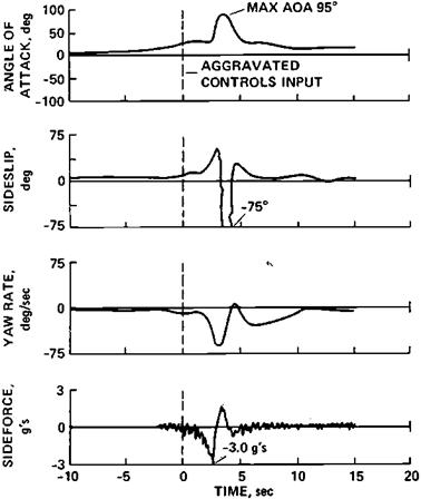
Figure 9.13 Transonic yaw departure obtained with a McDonnell Douglas F/A-18A by using pro­spin controls, or aileron against, and rudder with a turn at a medium angle of attack. (From Anderson, Enevoldson, and Nguyen, AGARD CP-347, 1983)

an angle of attack limiting system can be defeated in a number of ways, leading to excessive angles of attack.

McDonnell Douglas F/A-18A An automatic spin recovery mode, providing full control authority when yaw departure is sensed, can be defeated if the air­plane goes into a spin mode in which the yaw rate is relatively low. Although not a departure problem, the F/A-18A has an odd falling leaf spin mode, in­volving large sideslip, roll rate, and pitch rate oscillations. Response to pitch recovery control is slow. Finally, yaw departures are triggered by pro-spin con­trol applications at medium angles of attack and high subsonic Mach numbers (Figure 9.13).

Boeing F/A-18E/F An automatic spin detection and recovery mode has been added relative to older F/A-18 models. The falling-leaf characteristic of the F/A-18A/C is still present with the bare airframe. However, a new в feedback eliminates the falling-leaf mode (Heller et al., 2001).

Grumman EA-6B This airplane was not included in the AGARD survey paper by Anderson, Enevoldsen, and Nguyen. However, its nose-slice behavior at the stall is documented in AIAA Paper 87-2361 by Frank L. Jordan, David E. Hahne,

Matthew F. Masiello, and William Gato. Approaching the stall, the EA-6B first experiences a rolloff, followed by a nose slice. Numerous EA-6B accidents in fleet service attributed to departures led to a NASA research program on the problem (Chambers, 2000). An EA-6B fitted with NASA modifications (higher vertical tail, inboard wing leading-edge droop, etc.) had departure-free performance, but budgetary constraints prevented their application to service airplanes.

McDonnell Douglas F-15E Thisairplane islikewise not included in the AGARD survey. Its departure characteristics are described in Sitz, Nelson, and Carpenter (1997). Control laws are modified for yaw rates above 42 degrees per second, to increase differential tail power in recovery. Departures are found with lateral loading asymmetry. With the left wing loaded, at angles of attack above 30 degrees, rolls to the right are rapid and hard to counter.

Rockwell/MBB X-31 Departures of this research canard fighter at angles of attack of 60 degrees were corrected by a fuselage nose strake (Chambers, 2000).

The conclusion to be drawn from this survey is that departures can still be obtained on modern fighter airplanes. Designers should concentrate on understanding and controlling the vortex flows that often underlie departures, on simple warning cues and recovery procedures, and on crew restraint systems that permit functioning in the face of strong accelerations.

CHAPTER 10

The Lockheed S-3A Viking

Lockheed S-3A development followed a similar path to that for the McDonnell Douglas T-45A. That is, corrections for deficiencies found in the 1973 flight tests of the fourth S-3A airplane were stretched out over the next ten years. The original S-3A design had the same problem in carrier approaches as did the original T-45A Goshawk. With jet bypass engines delivering enough thrust at low engine rotation speeds to stay on the final approach path, “If all of a sudden you’re starting a settle coming into the carrier, you add power to regain altitude but nothing happens because of the delay in getting the engines to respond” (Wilson, 1992).

In the case of the S-3A, the belated fix was the direct lift control system described previously. Another belated stability and control fix to the S-3A for carrier suitability is thrust trim compensation. The S-3A’s low-slung engines produce longitudinal trim changes when power is used to adjust the final approach path angle, upsetting the desired constant angle of attack condition. The compensation moves the elevators automatically when the pilot adjusts the throttle position.

The Prospects for Safe Personal Airplanes

Commercial production in the United States of newly designed personal airplanes has been neglected for a number of years, the victim of high costs and liability suits. Kit – built airplanes have proliferated instead, with no apparent improvement in stability and control over the last commercial designs. Many kit airplane designs show inadequate tail lengths, spin resistance, and spin recovery features. This prevails in spite of the provisions of FAA regulations Part 21, which call for kit manufacturers to comply with the FAA Part 23 airworthiness requirements for light general-aviation airplanes.

U. S. amateur-built airplanes qualify as experimental under FAA Part 21 and are excluded from the Part 23 airworthiness provisions. A new FAA category of Ultralight Vehicles (Part 103) is also excluded from Part 23 regulations. Part 103 vehicles are VFR (Visual Flight Rules) airplanes weighing less than 254 pounds empty, with stalling speeds not more than 24 knots and maximum airspeeds less than 55 knots.

The hiatus in commercial production of new personal-airplane designs may bring about stability and control improvements. There are two key developments that make this likely: computer-aided design and satellite navigation. First, computer-aided design has been brought down to a level of cost and simplicity that makes it available to the general-aviation industry and conceivably to computer-wise kit builders. There are at least three such systems available.

The Design, Analysis and Research Corporation of Lawrence, Kansas, sells software called “Advanced Aircraft Analysis,” which allows users to size tail surfaces for stability, to compute stability and control derivatives, and to generate linearized dynamics. Another available computer-aided design scheme is that developed by Frederick Smetana, as a computerized version of the Perkins and Hage book Airplane Performance, Stability and Control. A third group of aerodynamic design and analysis computer programs specifi­cally designed for personal computers is marketed by the Desktop Aeronautics Company of Stanford, California. Desktop’s “LinAir Pro” computer program can be used to generate a complete set of stability derivatives for an airplane of arbitrary configuration. Accuracy should be comparable with that for preliminary design handbook methods.

With the availability of personal computer design programs such as those mentioned and others sure to be developed there really is no reason for basic errors in stability and control layouts to be made by kit airplane designers, not to mention the designers of the commercially built personal airplanes of the future. As a last resort, if the machine resembles a well-known existing airplane, and has a center of gravity near 25 percent of the wing chord, it probably will fly and can be made reasonably satisfactory by control surface and other modifications based on flight testing.

GPS satellite navigation is within the reach of general-aviation airplanes, with conse­quences for stability and control. Many small airports should be able to provide approved, charted instrument approaches. If instrument approaches become more common in general aviation, there will be increased attention needed to handling qualities under those condi­tions. Simplifying navigation with GPS should allow pilots to pay more attention to airplane control.

Heading Angular Velocity Correction and Initialization

The inertial reference for body axis heading angular velocity relative to the orbit plane in the Rockwell/Dryden formulation can be thought of as true north, defined by the local meridian. However, a local meridian cannot be used as an inertial reference unless its motion as the earth turns is accounted for. Powers and Schilling (1980, 1985) derive this correction.

The earth’s atmosphere is carried around with earth rotation, causing side winds relative to the orbit plane. This requires special initialization for starting transient response calculations at zero sideslip. Closed-form initialization formulas are available using initial angle of attack, velocity, and flight path angle.