Category Airplane Stability and Control, Second Edition

The Northrop F-89 Sideslip Stability Augmenter

The straight-wing twin-jet F-89 was originally flown with a conventional rate gyro yaw damper, with washout for steady turns. The rate gyro was replaced with a sideslip sensor, to reduce adverse (top) rudder angle in lead pursuit courses more than the yaw rate washout could do. The F-89 sideslip stability augmenter improved directional stability as well as Dutch roll damping.

20.2 Root Locus Methods of Analysis

One of the remarkable stories in the stability and control field is the invention of the root locus analysis method by Walter R. Evans. This came relatively late in the game for a fundamental advance in control system analysis. The root locus method first appeared in Evans’ Master’s degree thesis at the University of California, Los Angeles, followed by a North American Aviation report. The first root locus journal paper (Evans, 1948) was published over objections from referees who thought the work was of little

merit. While the method is known simply as the root locus method in the United States, Russian papers quite properly call it the Evans method. The root locus method received wide publicity with Dr. William Bollay’s 1950 Wright Brothers Lecture, but even before the 1948 journal publication it had “spread like wildfire,” according to Duane McRuer. This happened because John Moore at UCLA and Phillip Whittaker at MIT lectured on the method, using drafts of the North American report.

The essence of the root locus method is the set of rules that Evans discovered for the migration of roots of an open-loop system to the roots of the same system when the loop is closed. Airframe open-loop roots are nothing more than the airframe roots discussed by G. H. Bryan in 1911, the short – and long-period airplane modes of motion, and the aperiodic modes such as the spiral and roll modes. Evans found that the open-loop modes migrate toward the open-loop zeros as closed-loop gain is increased from zero (the open-loop case) to infinity. The open-loop zeros are the roots of the numerator function of each element’s transfer function.

Root locus methods survived from the 1950s to the present day as one of the most widespread flight control system analysis and synthesis methods. Modern variants are

z-Plane The z-plane root locus makes use of the z-transform, where z = eTs and s is the Laplace transform variable (Bollay, 1951). The complex number z is defined only at the switching or sampling times T of a sampled-data or digital control system. Since the states of sampled-data or digital control systems are likewise defined only at sampling times T, the z-plane root locus can be used for stability and performance analysis of these systems. In the z-plane, real parts of the variable z are plotted along the abscissa, while imaginary parts are plotted along the ordinate. The Evans s-plane root locus rules apply as well in the z-plane. Only the region of stability and lines of constant damping ratio differ.

w – and w ‘-Planes An improved transformation method for dealing with sam­pled-data or digital systems appeared in the 1950s, called the w-plane. The com­plex variable w iscreated by a bilinear transformation on z, or w = (z — 1)/(z +1). Richard F. Whitbeck and L. G. Hofmann (1978) describe a scaled version of the w-domain with even better properties. This is the w’-domain, in which w’ = 2w/T. In contrast to the z-plane, the left or stable half of the w ‘-plane corresponds to the left or stable half of the s-plane. Powerful analogies exist between the s – and w’-domains, allowing use of conventional root locus and Bode (Bollay, 1951) design tools. As a drawback, w’ transfer functions are far more complex algebraically than s transfer functions.

Unified Analysis Using Bode Root Locus The Bode root locus is a hybrid method developed by Duane McRuer (McRuer, Ashkenas, and Graham, 1973) that adds to the conventional Bode plot the amplitude ratios of the various loci in the s-plane. For any given loop gain actual closed-loop roots, all of the conventional frequency response quantities and the sensitivity to gain changes are seen in this plot.

Root Locus Sensitivity Vectors Sensitivity vectors can be drawn from unaug­mented airplane poles, such as the Dutch roll complex conjugate pair, giving the directions and magnitude in the complex plane of the migration of those poles for individual feedbacks. The effects on a Dutch roll mode of unconventional feedbacks, such as sideslip and lateral acceleration to the ailerons, can be com­pared. Root locus sensitivity vectors were first published by Duane McRuer and Robert Stapleford (1963).

The Effect of Folding Wings

Folding wings as a device for fitting very large airplanes into airport ramps, taxiways, and maintenance areas would have stability and control consequences. While fairly long wing sections could fairly readily be folded up, shortening fuselages by fold­ing hardly seems practical. This means that tail length in terms of wing spans would be reduced.

Longitudinal stability and control would be adversely affected by the shorter relative tail length of folding wing designs. Higher downwash and larger trim drag would result. There would be increased yawing moment due to rolling. An extended-span transport airplane would have some of the flight behavior of a high-performance sailplane, with strong demands on rudder power to coordinate rolls. However, the most adverse effect and most difficult to correct would be reduced rudder power for low-speed control with an engine out.

Even without folding wings, the current Airbus A3 80 layout has 10- to 20-percent reduced tail length in terms of wing span than current designs, such as the Boeing 747-400. The same adverse trends in stability and control as for the folding wing case, noted above, might be expected.

Equivalent System Models and Pilot Rating

The 1980 military flying qualities specification MIL-F-8785C represents the cul­mination of the representation of airplanes by classical transfer functions (see 20.4), the transfer functions of bare airframes augmented only by simple artificial damping and cross­feeds, where needed. In pitch, the bare airframe transfer function of pitching velocity as an output to control surface angle as an input has an inverse second-order denominator and a first-order numerator under the constant airspeed assumption. Three parameters define this function: natural frequency and damping ratio in the denominator and the numerator time constant. The classical bare-airframe transfer function models are called equivalent systems because they can only approximate the transfer functions of complex, augmented flight control systems, such as command augmentation systems and the newer superaug – mented systems for highly unstable airframes. The uses to which equivalent system models are put in specifying longitudinal and lateral flying qualities are illustrated in Chapter 10, “Tactical Airplane Maneuverability.”

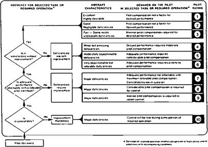
The 1980 specification MIL-F-8785C represented another culmination in the develop­ment of airplane flying qualities as a science. This is assigning a numerical scale to pilot opinion. In the 1950s A. G. Barnes in the United Kingdom used the initials G, M, and B for good, medium, and bad, with + and — modifiers. The numerical scale, running from 1 to 10, was proposed by George E. Cooper in 1961. The MIL-F-8785C uses the Cooper-Harper rating scale (Figure 3.11), in which the experience of NASA and Calspan are combined (Cooper and Harper, 1969).

A successor to the Cooper-Harper rating scale originated at the College of Aeronautics, Cranfield University (Harris et al., 2000) to deal better with modern fly-by-wire aircraft. The proposed new scale, called the Cranfield Aircraft Handling Qualities Rating Scale, or CAHQRS, considers separately five parameters – longitudinal, lateral, directional, trim, and speed control – and rates behavior in subtasks according to a Cooper-Harper-type scale, and also a criticality scale. The CAHQRS has been tested initially on a flight simulator. Further

Equivalent System Models and Pilot Rating

Figure 3.11 The Cooper-Harper pilot numerical rating scale, now a definitive standard. (From NASA TN D-5153, 1969)

experience with this new approach is needed to confirm its expected benefits relative to the Cooper-Harper standard.

The next phase in the unfolding history of the science of flying qualities involves a new level of sophistication, freeing the subject from the constraint of equivalent systems. Mathematical models of the human pilot as a sort of machine are combined with airplane and control system mathematical models and are treated as a combined system. Human physiology and psychology are now enlisted in the study of flying qualities requirements. These interesting developments are treated in Chapter 21, “Flying Qualities Research Moves With the Times.”

Spoiler Steady-State Aerodynamics

Separation behind an opened spoiler on a wing upper surface causes distortion of the external or potential flow that is similar to the effect of a flap-type surface with trailing-edge-up deflection. In the latter case, streamlines above the wing are raised toward the wing trailing edge. The effective wing camber is negative in the trailing-edge region, causing a net loss in circulation and lift. The difference in the two cases is that the effective wing trailing edge in the spoiler case is somewhere in the middle of the separated region, instead of at the actual trailing edge, as in the flap-type surface case.

5.10.1 Spoiler Operating Forces

The hinge moments of ordinary hinged-flap and slot lip spoiler ailerons are high; brute hydraulic force is used to open them against the airstream. Retractable arc and plug spoiler ailerons are designed for very low hinge moments and operating forces. Although aerodynamic pressures on the curved surfaces of these ailerons are high, the lines of action of these pressures are directed through the hinge line and do not show up as hinge moments. Hinge moments arise only from pressure forces on the ends of the arcs and from small skin friction forces on the curved surfaces.

The B-52 Manually Controlled Ailerons Are Small

The B-52 has only the smallest of ailerons, in the conventional sense. The ailerons are of conventional chord, but their span is only about equal to their chord. They are quite aptly called “feeler ailerons,” in that their main function is to supply control forces to the pilot’s yoke. Spring tabs are used on the feeler ailerons. Six upper surface spoiler segments on each wing provide the real roll control power for the airplane. The spoiler actuators get their signals to come open from the rotation of the pilot’s control wheel, requiring no pilot effort to operate.

The spoiler aileron system adopted for the B-52 was originally tested on a B-47, after that airplane exhibited a marked loss in conventional outboard flap-type aileron power due to wing twist. The spoiler system worked well on the B-47, but the Air Force declined to make the change on that airplane. The B-52 can be landed using the feeler ailerons alone, if all

The B-52 Manually Controlled Ailerons Are Small

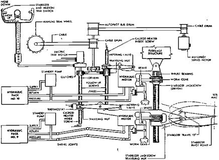
Figure 7.6 Schematic ofthe Boeing B-52’s stabilizertrimcontrols. Two independenthydraulic motors drive the stabilizer, onethroughthejackscrew, the otherthroughthejackscrew’straveling nut. The valve of each hydraulic motor is controlled by electric trim motors, with mechanical backup. (From B-52 Flight Manual, 1956)

spoilers are inoperative due to hydraulic power failures, for example. Successful landings are possible under benign wind and turbulence conditions.

In the late model B-52G the feeler ailerons have been eliminated and an extra spoiler segment has been added. The B-52G flight manual advises that limited lateral control is available by sideslipping the airplane with the rudder, if all spoilers are inoperative. Landings are “not advised” by the flight manual, meaning that the crew is expected to bail out if all spoilers become inoperative.

CHAPTER 8

Rapid Rolls to Steep Turns

Effective use of ailerons for rapid rolls to steep turns requires not only good roll response but also coordination, or the suppression of adverse yaw. The airplane’s lift vector should remain close to the airplane’s plane of symmetry during the roll and turn entry. The ball of the turn and slip indicator (see Chapter 15, Sec. 10.1) will then remain close to center, and the maneuver will be called coordinated. An alternate coordination condition is suppression of sideslip, which puts the velocity vector in the airplane’s plane of symmetry.

Starting with the 1943 Gilruth requirements for satisfactory flying qualities, coordination requirements were examined in rapid aileron rolls with the rudder held fixed at the initial trim position. The peak sideslip excursion and the phase angle of the Dutch roll component of the excursion were correlated with pilots’ ratings and used as the basis of U. S. Air Force coordination requirements.

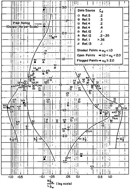
More recent studies of tactical airplane roll response and steep turn entries have focused instead on the use of the rudder for coordination. Airplane transfer function theory has been applied, as in the case just described for pitch maneuvers. As in Figure 10.10, pilot ratings are compared with parameters derived from the roll and sideslip due to aileron and rudder transfer functions (Hoh and Ashkenas, 1977). Rudder deflection is assumed to be used in a coordinated fashion to hold the sideslip angle to zero in abrupt aileron rolls, as pilots are trained to do. The essence of the Hoh and Ashkenas method is a solution for the precise rudder cross-feed that accomplishes this, using linearized transfer functions.

Rapid Rolls to Steep Turns

Figure 10.10 Required rudder cross-feed to coordinate turn entry, a significant factor for airplanes with good Dutch roll characteristics. The amount and sense of rudder required isplotted on the abscissa. The ordinate і shows the required phasing of the rudder input. Rudder angle is sustained after initial input for positive values of і and reversed for negative values of і. The greatest pilot tolerance for required cross-feed occurs with і = —1.0, for which cross-feed fades to zero after the turn is established. (From Hoh and Ashkenas, Jour. of Aircraft, Feb. 1977)

The solution is in two parts, magnitude and phasing. The phase dependence means that, depending on the details of the airplane’s lateral-directional dynamics, the required rudder deflections for coordination, or cross-feed, may increase or decrease after the initial rudder application.

The end result of the analysis shows a strong favorable effect for a particular required rudder cross-feed phasing. Pilots tolerate the largest amount of rudder angle cross-feed for the case in which the required rudder angle tapers off toward zero as the turn is established. Conversely, if the required rudder angle cross-feed either increases beyond the initial value or changes sign during the turn, pilot ratings suffer and smaller cross-feed levels are tolerated.

The cross-feed phasing parameter г that expresses all of this is derived from the ratios of the transfer function numerators of rudder to sideslip and aileron to sideslip. Excluding low (gravity) and high (direct force) frequency terms, the parameter г expresses the separation between simple zeros in these numerators. Positive values of г correspond to increasing rudder requirements during the turn and negative values to decreasing rudder requirements. The optimum case, in which the steady-state value in a turn goes to zero, corresponds to г = -1.0.

Turning Human-Powered Ultralight Airplanes

Roll and yaw control have emerged as major problems for human-powered ultra­light airplanes. This appeared in the competition for the first Kremer Prize. Winning the prize required that a figure-eight maneuver be performed around pylons one-half mile apart. Henry R. Jex (1979) says:

Early analyses [of the Gossamer Condor]… revealed the futility of conventional aileron control for roll, the need for some fin area to enhance Cye and Cne; and the seeming paradox that twisting the wing for a leftward rolling moment would quickly produce a yawing velocity and roll angle to the right! … Warping the wings for a left-wing-down rolling moment immediately creates a large nose-right adverse yaw torque of about 15 percent of the rolling torque. Because the effective inertia in yaw is less than 1/5 of that in roll [due to the large roll apparent mass] and the weathervane stability is very small, the airframe immediately starts to yaw right. The strong rolling moment from yawing [due to the outside wing moving faster than the inside wing] quickly overpowers the [control rolling moment due to wing warp], so the airplane starts to roll right within about 2 seconds!

The initial Gossamer Condor version could not be turned with spoiler ailerons. A solution was found for this failure of conventional aileron control for ultralight airplanes in the invention of a new control method. Like the Wright brothers, the inventors of the new

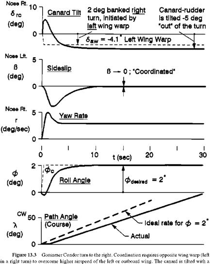
control method, Dr. Paul B. MacCready, Dr. Peter Lissaman, and James D. Burke, applied for a patent for their scheme. In the new method, pilot roll control tilts the canard and its lift vector by means of tabs at the outboard trailing edge and concurrently warps the wing in the opposite direction. Nose-right tilt of the canard and the adverse yaw of the leftward warped wing pull the nose right. The airplane is rolled right by the strong rolling moment due to right yawing Clr. The result is a slightly overbanked turn in which inward (right) sideslip develops. Canard tilt is reversed a little later. The final wing and canard settings for a stabilized, coordinated right turn at a 2.0-degree bank angle are 4.1 degrees of left wing warp and about 5 degrees of left canard tilt (Figure 13.3). Because ofthe ultralight airplane’s low flight speed of 16 feet per second, the 2.0-degree bank angle produces a standard rate “needle-width” turn of 180 degrees per minute. The turn radius is 300 feet.

Turning Human-Powered Ultralight Airplanes

1-second pulse of aileron tab initially to the right, to start the turn. Canard tilt is then reversed to keep from overbanking the airplane. The resultant 3-degree-per-second yaw rate is sufficient. (From Jex and Mitchell, NASA CR 3627, 1982)

13.6 Concluding Remarks

Ultralight airplanes have satisfied a need for inexpensive, lightly regulated ma­chines. At the same time, microlight versions have proved to be useful in specialized applications such as surveillance and crop dusting. Stability and control deficiencies have surfaced that had no previous history. Inadvertent stalling is a significant cause of accidents.

Human-powered ultralight airplanes have been useful for the original thinking that they have inspired, more than for the utility of the machines produced. But having developed new stability and control concepts for some of these machines, one would like to see the scaling laws that connect these concepts with the characteristics of conventional airplanes. It would be instructive to see how the anomalous longitudinal and turning behavior of human – powered ultralights blends into normal flight dynamics. Dr. Paul MacCready also suggests quantitative attention to bird stability and control for their approach to active control of unstable flight systems.

Other Variable-Sweep Projects

The reason that a British team under Dr. Barnes Wallis at Vickers-Armstrongs was available to work on variable sweep with the NASA Langley group in 1959 was that Wallis could not get British government funding for full-scale variable-sweep tests. Inspired by wartime German research, Wallis had actually started variable-sweep research in Britain in 1945, using models launched from a rocket-powered trolley After some success­ful model flights, Vickers-Armstrongs contracted for a small piston-engine variable-sweep test airplane with Heston Aircraft Ltd., but the parts built were never assembled and were eventually broken up.

In 1959, Wallis brought the Vickers-Armstrongs variable-sweep team and data to NASA’s Langley Laboratory for further research. At the time, the variable-sweep configuration of interest to the British was a high-aspect-ratio tailless arrangement in which the wing inboard ends required translation. The British called this arrowhead-like configuration “Swallow.” The Swallow was to lead to a high-subsonic airliner capable of flying nonstop from London to Australia at 50,000 feet. NASA wind-tunnel tests indicated that the Swallow would be longitudinally unstable with the wings unswept at low subsonic speeds (Figure 16.6). A return to horizontal tails and the successful outboard-hinge rotation-only arrangement followed.

Later practical applications of variable sweep were the Anglo-German-Italian Panavia Tornado and the former USSR’s MiG-23 Flogger, MiG-27, Su-17, Su-24, Tu-22M Backfire, and the Tu-160 Blackjack.

The Effect of Wing Sweep on Torsional Divergence

One of the rare benign effects of wing sweepback, aside from its function in reducing transonic drag and instability, is the virtual elimination of the possibility of wing torsional divergence. A wing that is swept back bends under lift loads in a direction that reduces or washes out incidence at the wing tips. This provides automatic load relief.

By the same token, a wing that is swept forward bends under lift load in the opposite sense, increasing the wing tip incidence and load. This adds to the wing-bending deflection and the load in the classic feed-forward sense, producing torsional divergence at sufficiently high airspeeds. Thus, although swept forward wings are free of the premature tip flow separation problems mentioned in Chapter 11, “High Mach Number Difficulties,” they had for many years been dismissed from consideration for new high-speed airplanes.

A classic paper gave the first published account of the effects of sweepback and sweep – forward on wing torsional divergence (Pai and Sears, 1949). A striking aspect of this early paper is the statement of the fundamental equation of aeroelasticity in matrix form. This is an integral equation for the local, or section lift, coefficient. The choice of aerodynamic theory is left free. In 1949, the choices were strip theory, which neglects aerodynamic induction; Prandtl theory; and Weissinger’s approximation.

The advent of composite materials as aircraft structural elements has reopened the door to the sweptforward wing. In 1972, Professor Terrence A. Weisshaar at Purdue University studied the divergence and aeroelastic optimization of forward-swept wings, under a NASA grant. His student, a returning Vietnam veteran fighter pilot named Norris Krone, proposed a PhD thesis on fighter sweptforward wings.

With additional help from Professor Harry Schaeffer, Krone proposed building swept- forward wings in which layers of fiber-plastic composites are oriented to increase greatly torsional stiffness. Such wings could have torsional divergence speeds well out of the flight range. Later, as an official in the Defense Advanced Research Projects Agency, Krone had the unusual opportunity to help turn his research into a practical airplane, the successful Grumman X-29A research airplane.

Robust Controllers, Adaptive Systems

Robust flight control systems are designed specifically to perform well in the face of airframe, sensor, and actuator uncertainties and even failures. An early robust flight control system approach was the adaptive control system, a particular research objective of the Honeywell Corporation. This was in the days before airborne digital computers. The modest objective was to identify the airplane’s pitch natural frequency by periodic injection of small test pulses of elevator control. Pitch natural frequency variations reflected changes in both center of gravity location and dynamic pressure, or calibrated airspeed. Control system gain was lowered at the higher pitch natural frequencies to maintain system stability.

Modern applications of adaptive control make use of parameter identification, although test signals are still required to keep the parameter identification loop from going unstable. In a 1982 NASA workshop on restructurable controls, reasonably good results were reported for two adaptive schemes (Cunningham, in Montoya, 1983). Horizontal tail effectiveness Ms was identified on a Vought F-8 sufficiently well for autopilot gain scheduling through the flight envelope. Also, the flutter modes of a wind-tunnel model of a wing with stores (weapons) were identified by maximum likelihood methods.

The same NASA workshop brought a theoretical criticism of all adaptive systems by MIT professor Michael Athans. In his words:

Over two thousand papers have been written [on adaptive control] and a lot of excitement generated. You may have seen that people are giving courses to industry on how to make adaptive control practical. We have a recent MIT Ph. D. thesis [Rohrs, 1982] finished in November 1982 that Dr. Valvani and I supervised, which proved with a combination of analytical techniques and simulation results that all existing adaptive control algorithms are not worthwhile.

The algorithms may look excellent if you follow their theoretical assumptions, but in the presence of some persistent output disturbances and unmodeled high frequency dynamics all adaptive control algorithms considered become unstable with probability one.

Aside from coping with center-of-gravity and flight condition changes, robustness in control systems already exists in augmentation systems incorporating self-checking redun­dant digital computers. Robustness against sensor failures has also been demonstrated with redundant inertial sensors in skewed orientations. Failure of one or two sensors leaves the system fully operational. Failure of a single airspeed meter due to icing resulted in the losses of a General Dynamics B-58 Hustler and of an US/German X-31A research airplane. The automatic pilot gain-changing features interpreted the iced meter readings as low airspeed, requiring higher gains (communication from Dr. Peter Hamel).

Robustness against actuator failures, and especially against failures that result in control surfaces that go hard over against a stop and stay there, is another matter. The stirring example of Delta Airlines’ pilot McMahan who saved a Lockheed 1011 with one elevator against the up stop is told in Chapter 5, “Managing Control Forces.” System concepts for reconfiguring control systems to cope automatically with major failures are still in the early stages.

While waiting for the development of systems that are robust in the face of actuator hardovers, Thomas Cunningham suggests two straightforward aids for the human pilot. The position of each individual control surface should be measured and displayed in the cockpit. Captain McMahan did not know that the 1011 elevator was against its stop. Also, engine controllers should be designed to the higher bandwidths needed for differential thrust control of a crippled airplane.