Category Airplane Stability and Control, Second Edition

The Discovery of Inertial Coupling

Airplanes that fly near the speed of sound are designed with thin, stubby wings. Most of their masses are concentrated in the center, in long, slender fuselages. When these airplanes are rolled rapidly the fuselage masses tend to swing away from the direction of flight and become broadside to the wind. This tendency, essentially a gyroscopic effect, is called inertial coupling.

8.1 W. H. Phillips Finds an Anomaly

The distinction of having discovered inertial or roll coupling in airplanes and then explaining it mathematically in the open literature belongs to W. Hewitt Phillips, then working in the Flight Research Division of the NACA Langley Laboratory. In a 1992 paper Phillips said, “When the [XS-1] model was dropped, it was observed in the optical tracker

to be rolling, as shown by flashing of light from the wings____ In examining the records

further the oscillation… was found to represent a violent pitching in angle of attack from the positive to the negative stall” (Figure 8.1).

Phillips analyzed the problem as a gyroscopic effect, publishing his results in an NACA Technical Note (Phillips, 1948). In those days NACA used the category of Technical Notes for “the results of short research investigations and the results of studies of specific detailed problems which form parts of long investigations.” Well, nobody’s perfect – the NACA could hardly be blamed for missing the fundamental importance of Phillips’ inertial coupling results when so many other people took little notice. In hindsight, the inertial coupling analytical work clearly merited publication in the more exalted category of NACA Technical Reports as the “results of fundamental research in aeronautics.”

Supermaneuverability, High Angles of Attack

Until the 1970s, fighter air-to-air combat followed the pattern set during World War I. Fighter pilots maneuver behind opposing fighters to bring fixed guns to bear long enough for a burst. The tactics are much the same for narrow-field-of-view guided missiles, such as the AIM-9 Sidewinder. In the missile case, a tail position is held long enough for an acquisition tone; then the missile is launched.

Hawker-Siddeley in Britain came up with the thrust-vector-controlled Taildog missile concept in the late 1960s, making an off-boresight launch a possibility. Combined with a helmet-mounted sight, a Taildog-type missile can be launched at target airplanes at almost any position where the pilot can follow the target with his eyes. However, even with off – boresight missile lockons and launches now possible, there is still interest in gunnery for air-to-air combat. Furthermore, there is interest in gun bearing at high angles of attack, increasing firing opportunities in a dogfight.

Supermaneuverability is defined as controlled, or partially controlled, flight in the stalled regime. It takes two forms: first, a dynamic maneuver to a high angle of attack, beyond any equilibrium or trim point. Pitching angular momentum carries the airplane to a momentary peak angle of attack. The second form of supermaneuverability is flight to a sustainable trim equilibrium beyond the stall. Supermaneuverability is seen as a way to get into the tail chase position, by a feint, tricking a pursuing airplane into overrunning one’s position. Supermaneuverability adds to a dogfighting airplane’s options.

The Cobra maneuver, demonstrated with a Sukhoi Su-27 airplane by the Russian pilot Viktor Pugatchov at Le Bourget in 1989, is in the first category. After Pugatchov’s demon­stration in the Su-27, the same maneuver was performed in a MiG-29. The Cobra is started from unstalled flight with a rapid application of full nose-up control, which is held up to the maximum angle of attack point, about 90 degrees. Control is neutralized for the recovery, assuming that the airplane has a negative or nose-down pitching moment at that point.

The entire maneuver takes about 5 seconds. There is a small altitude gain but a huge loss in airspeed and kinetic energy. Ordinarily, during air combat, one tries to maximize airspeed and total (potential plus kinetic) energy as a reserve for further maneuvers. Thus, U. S. Major Michael A. Gerzanics, project test pilot for a vectored-thrust F-16, has stated that supermaneuverability is not beneficial in all tactical situations, but is rather something that he would like to have available for close combat with a strong adversary. Clearly, any un­controlled yawing and rolling moments that develop in the 5-second period beyond the stall must be small. The Cobra maneuver has been elaborated with a sidewise variant, called the Hook.

10.2 Unsteady Aerodynamics in the Supermaneuverability Regime

Mathematical modeling in the supermaneuverability regime has to account for unsteady aerodynamic effects above the stall (Zagainov, 1993). Zagainov describes a state variable mathematical model, developed by M. G. Goman and A. N. Khrabrov, for coef­ficients such as Cz and Cm. The model has a first-order state equation that defines time dependence (Figure 10.11). The typical hysteresis loop found in forced oscillation tests into the stalled regime can be modeled in this way. Zagainov also discusses the strong rolling and yawing moments that appear in the angle of attack range where vortices are shed from inboard strakes and extended forebodies. These vortex-generated rolling and yawing mo­ments not only appear to exceed values measured in steady wind-tunnel tests, but they are also time-dependent, exhibiting hysteresis loops.

Additional light on the complex, unsteady air flows in the supermaneuverability regime has been shed by a combined wind-tunnel test and flow visualization program (Ericsson and Byers, 1997). A major factor is a coupling between vehicle motion and asymmetric cross-flow separation on a slender forebody. Wing leading-edge extensions or LEX, such as found on the F-16 and F-18 airplanes, change the nature of the cross-flow separation, apparently in a beneficial direction.

Fuel Slosh, Deep Stall, and More

In nearly 100 years of controlled flight the stability and control field has seen any number of special gadgets and phenomena that fit into no general category We recall some of the most interesting of these.

14.1 Fuel Shift and Dynamic Fuel Slosh

The term fuel shift refers to long-term motions of the fuel in a partially filled tank, such as a shift to the rear of an airplane’s tank caused by a prolonged nose-up attitude, in a climb. The causes and effects of fuel shift are apparent. Aft fuel shift could move the airplane’s center of gravity to a dangerously rearward position. This possibility is generally considered by every designer. There is even the possibility of fuel starvation if the tank feeds the airplane’s engine from a forward sump.

Dynamic fuel slosh occurs when fuel in a partially filled tank, be it an automobile or airplane tank, sloshes around inside the tank in response to changing vehicle accelerations. As the tank walls contain the sloshing fuel, transient forces are transmitted to the walls, and the vehicle, by the fuel. Dynamic fuel slosh can be a problem in airplane stability and control if the fuel modes of motion couple with the airplane’s normal modes of motion. The dynamic fuel slosh problem is worth examining because modern jet airplanes tend to have high ratios of fuel to gross weight and slosh motions could have a considerable effect. Also, on airplanes with relatively thin wings, the main tankage tends to be in the fuselage. Wing tanks are generally interrupted by structural members, which act as baffles to fuel motion, while fuselage tanks can have large uninterrupted volumes.

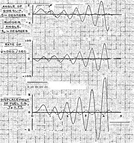
Although dynamic fuel slosh is an intriguing mathematical and engineering problem, documented cases of dynamic fuel slosh coupling with an airplane’s modes of motion are rare. There was a verified case of dynamic fuel slosh coupling with the Dutch roll mode of motion on the Douglas A4D Skyhawk. Partial fuel in a 500-gallon fuselage tank forward of the center of gravity caused undamped roll-yaw oscillations during landing approaches (Figure 14.1). The problem was corrected when fore-and-aft vertical tank baffles were added to the fuselage tank, dividing the tanks into left and right halves. The baffles almost doubled the fuel slosh frequency, decoupling slosh from the Dutch roll.

There was another reported dynamic fuel slosh problem on the Lockheed F-80C airplane. This was during an all-out drive to improve the loitering capability of F-80s in the early months of the Korean War. F-80 units in Korea started carrying unbaffled 265-gallon tip tanks, but soon reported unexplained crashes. At the request of Headquarters, Far East Air Forces, Wright Field flight-tested the 265-gallon tanks on an F-80C.

In a test flight in November 1950, James D. Kelly found no flight problems at takeoff and climb-out, when the wing tip tanks were essentially full. Later, with partial tip tank fuel, an uncontrollable pitching motion started. Kelly could see the wing tips twisting as fuel sloshed fore and aft. He recovered control only after the left tip tank collapsed and fell away and he could jettison the right tank.
Fuel Slosh, Deep Stall, and More—1^—R UPPER mPUT

VAW

LIMUMITEO ; i;:

f • • ‘ .1 • ‘ *: Y^. LIMITED TO. IS FT.

Later лі­

ті me hSEC

Figure 14.1 Calculated effectof fuselage tank slosh in the Douglas A-4 Skyhawk before installation of a fuselage tank baffle. Fuel motion couples with the Dutch roll mode of motion. With the fuel mass motion limited by the tank sides (dotted curves), a steady limit cycle “snaking” motion results. (From Abzug, Douglas Rept. ES 29551, 1959)

Two additional dynamic fuel slosh cases are known, both documented in U. S. Air Force flight test reports. Both involved fuel slosh coupling with the Dutch roll mode of motion and were excited when the rudder was used to stop the yawing component of the Dutch roll motion. The airplanes with this problem were the Boeing KC-135A and the Cessna T-37A.

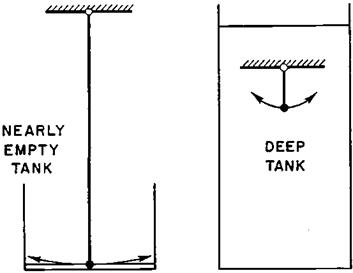
An analytical approach to the problem of dynamic fuel slosh coupling with the modes of airplane motion was made possible by a model proposed by Ernest W. Graham (Luskin and Lapin, 1952). Graham used the velocity potential for liquid in a rectangular open-top tank given in Horace Lamb’s classic Hydrodynamics. Sloshing fuel is modeled as a simple pendulum plus a fixed mass below the pendulum. The pendulum angle from the vertical is taken as the average fuel surface angular displacement in its fundamental mode of motion (Figure 14.2). The fuel’s general motion has higher harmonics, of shorter wave lengths, all of which are neglected to define the equivalent pendulum.

Fuel Slosh, Deep Stall, and More

Figure 14.2 Ernest W. Graham’s pendulum analogy to sloshing fuel in open-top rectangular tanks, illustrated by two extreme cases. All of the fuel sloshes in the nearly empty tank, but in just the upper portion of the deep tank. (From Luskin and Lapin, Jour. of the Aeronautical Sciences, 1952)

The pendulum analogy to dynamic fuel slosh depends mainly on the depth of the fuel in the tank. In the nearly empty case, fuel slosh is simply the wave action in a shallow container. The equivalent pendulum is long, and so is the period of the sloshing motion. In the nearly full or deep tank, the equivalent pendulum is short and so is the slosh period. Graham’s model permitted subsequent analysts to treat the problem of fuel slosh by adding the equivalent pendulum to the equations of airplane motion, as an additional degree of freedom for each partially filled tank.

Albert A. Schy, a skilled NACA analyst, set up the fuel slosh problem without using the Graham pendulum model, by assuming fuel is carried in spherical tanks (Schy, 1952). While spherical tanks are never seen in airplanes, Schy’s model is altogether equivalent to Graham’s model for conventional rectangular or prismatic tanks. Schy’s calculations show significant coupling into the Dutch roll mode of an airplane when the sloshing fuel mass is one-fourth the weight of the airplane.

Dynamic fuel slosh coupling with the longitudinal short – and long-period modes of motion is seldom a problem. There is a slight loss in short-period mode damping, but the long-period or phugoid mode cannot couple measurably with fuel in a partially filled tank unless the fore and aft dimension of the tank is impossibly long (Luskin and Lapin, 1952). Recent dynamic fuel slosh studies on a modern swept-wing jet with long fuel tanks running parallel to the wing spars came up dry, in the sense that slosh in any pair of partially filled tanks had negligible effects on the aircraft’s modes of motion.

In contrast to the modest effects of dynamic fuel slosh (but not long-term fuel shift) for the airplane case, dynamic fuel slosh has been an ongoing concern for large liquid-fueled boost or launch vehicles, such as NASA’s Saturn V Launch vehicle dynamic fuel slosh problems have included coupling with controlled pitch and yaw modes of motion as well as with elastic body bending modes.

Turning to the fuel shift problem in airplanes, an interesting case occurred on the Douglas A4D Skyhawk during early test flights. The A4D’s ultrasimple fuel system has only two

Fuel Slosh, Deep Stall, and More

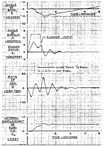
Figure 14.3 Calculated effect of fuel shift in the Douglas A-4 Skyhawk’s wing tip—to—wing tip wing tank. With half-wing fuel, a rudder kick shifts the fuel, giving apparent spiral instability. The bank angle increases slowly with time. (From Abzug, Douglas Rept. ES 29551, 1959)

tanks, the fuselage tank, which had sloshing problems before a baffle was installed, and a single integral wing fuel tank, which runs from wing tip to wing tip. The wing ribs provide excellent slosh baffling, but prolonged lateral acceleration can transfer partial wing fuel across the airplane’s centerline.

A4D wing fuel shift shows up as spiral instability, easily corrected by the ailerons (Figure 14.3). However, the early A4D airplanes had a single, or nonredundant, aileron hydraulic

system. When aileron hydraulics malfunctioned at a high Mach number during an early test flight the airplane and pilot James Verdin were lost. The painful lesson was learned. Production A4D (now A-4) airplanes retain the single integral wing fuel tank, but dual, independent aileron power systems now guard against loss in lateral control due to fuel shift.

Another fuel shift incident from the same time period occurred at Wright Field in a North American YF-100 being flown by Captain H. Z. Hopkins. He took off for a short functional check of the 275-gallon external fuel tanks. Only 50 gallons were loaded into each tank; takeoff acceleration shifted this load aft. Fuel was being burned from the forward fuselage tank, adding to the aft shift in cg. The cg apparently shifted aft behind the maneuver point, the point at which pull stick forces are required for positive-load factors. The airplane went through a rapid sequence of positive and negative maneuvers. The external tank fuel somehow shifted forward, and the structurally damaged airplane was brought back under control and landed.

Modern Canard Configurations

The 1903 Wright brothers’ Flyer was of course a canard airplane, with its hori­zontal tail in front. However, in the years that followed, up to quite recent times, canard configurations were definitely a curiosity, out of the mainstream. Conservative stability and control engineers think this is just as well.

17.1 Burt Rutan and the Modern Canard Airplane

Elbert L. (Burt) Rutan is an original thinker, a classic inventor, who left jobs at the Edwards Air Force Base and with Jim Bede in Kansas to build experimental personal airplanes at Mojave Airport, California. His Rutan Aircraft Factory, in a barracks-style building, became the home of the VariEze and Long EZ fiberglass canard airplanes. These designs have been built in large numbers from Rutan Aircraft plans by home builders. The excellent speed and climb performance of these little machines, compared with mass – produced, all-metal general-aviation airplanes, led to several major canard projects by Scaled Composites, Inc. One of these was the Beech Model 2000 Starship 1, an 8- to 11-seat business aircraft.

Rutan’s successes with the VariEze and Long EZ, with the canard round-the-world Voyager, and with the Beech projects have inspired many new canard home-built sport aircraft projects in the United States. Among them are the American Aircraft Falcon series, the Beard Two Easy, the Co Z Development Cozy, the Diehl XTC Hydrolight, the Ganzer Model 75 Gemini, and so on. What can we say about this trend? Some corrective notes on the supposed advantages of the modern canards, and on canard stability and control pitfalls, seem in order, in the hope that future designers will be fully informed.

Aileron-Reversal Theories

Aileron reversal is closely related to wing torsional divergence, involving also quasi-static wing twist. Aileron reversal limits roll maneuverability at high airspeeds and low altitude. At airspeeds where wings are still within structural limits, torques exerted on wings by deflected ailerons can twist the wing in the opposite direction enough to cancel much of the aileron’s lift or rolling moment, and even to reverse the aileron’s effect. The airspeed at which complete rolling moment cancellation occurs is called the aileron-reversal speed (Figure 19.2). Like a wing’s flutter or torsional divergence speeds, aileron-reversal speed should be only a theoretical number, quite outside of the airplane’s operating envelope and with an adequate safety margin.

Aileron-Reversal Theories

Figure 19.2 An example of the effect of wing flexibility on available rolling velocity. Data for the Republic P-47C-1-RE at an altitude of 4,000 feet. Aileron reversal occurs at 545 miles perhour. (From Toll, NACA Rept. 868, 1947)

Theoretical work on aileron reversal fits into Etkin’s quasi-static category. The earliest published work on aileron reversal was necessarily simplified, with the computing resources available at that time (Cox and Pugsley, 1932). The wing is represented in the same semi­rigid manner described for the wing torsional divergence problem. That is, a reference section along the wing is selected and the elastic restoring moment is related to the angular deflection at that station. A modern example of the semi-rigid approach to aileron reversal is given by Bisplinghoff and Ashley (1962).

An extension of the semi-rigid approach yields one of the most useful concepts in static aeroelasticity, the ratio of elastic to rigid control surface effectiveness. For the simple two-dimensional case, this ratio depends only on the flexibility influence coefficient, or twist angle per unit applied torque, the changes in section lift coefficient per unit section angle of attack and aileron deflection, the change in section moment coefficient about the aerodynamic center with aileron deflection, and the ratio of the distance between the elastic axis and aerodynamic center to the section chord length.

In a sense, everything that came after the two-dimensional, or semi-rigid, approach was refinement, to deal adequately with problems of real airplanes. For example, in 1945, Dr. Alexander H. Flax expressed the wing twist spanwise distribution as a superposition of modes with undetermined magnitudes. Mode magnitudes are found by the virtual work principle, in a solution of simultaneous algebraic equations. Many authors call this Galerkin’s method. Still later, finite-element methods permitted a direct solution that eliminated the need for assumed mode shapes.

Robust Controllers, Singular Value Analysis

The analysis of robust controllers took a different tack from adaptive controls with the work of J. C. Doyle and his associates, starting around 1980. The key to the new approach is a generalization of system gain using the singular values of a matrix. Matrix singular values are another term for the matrix norm, defined as the square root of the sum of the squares of the absolute values of the elements. The matrix norm is the trace of A* A, where A is the given matrix and A* is the Hermitian conjugate of A (or the transpose if A is real).

According to the singular value approach, control system robustness against uncertainties in mechanical and aerodynamic properties is assured if the amplitude of the maximum expected uncertainty is less than the minimum system gain at all frequencies.

A simpler, but equally important application of singular value analysis is to system stabil­ity margins, without considering uncertainties. Stability margins are guaranteed if the mini­mum singular values of the system’s return difference matrix are all positive (Mukhopadhyay and Newsom, 1984). The system return difference matrix I + G is a matrix generalization of the closed-loop transfer function denominator for a single-input single-output system. This stability margin application of singular value analysis was made for the X-29A research airplane (Clarke et al., 1994).

The Problem of Control

Otto Lilienthal (1848-1896), Sir Hiram Maxim (1840-1916), and Dr. Samuel Pierpont Langley (1834-1906) followed the empirical route, much as did the Wrights, but they failed to demonstrate man-carrying mechanical flight mainly because they underesti­mated the problem of control. Lilienthal died of a broken back after losing control of his hang glider. Langley’s airplane flew stably in uncontrolled flight as a quarter-scale model but broke up twice in full-scale launches. Maxim’s steam-driven airplane might have flown, but it broke free of the down-holding rails on its test track and was wrecked.

The Problem of Control

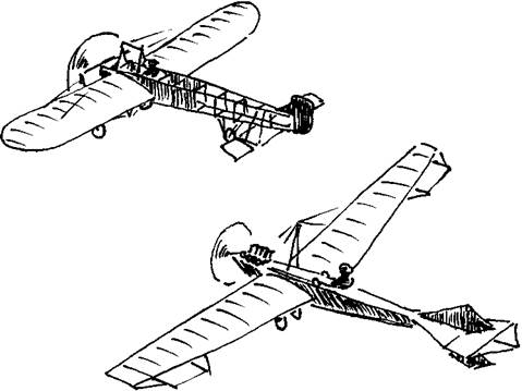
Figure 1.1 Two early flying machines with inherent longitudinal and lateral stability, the Bleriot XI Cross-Channel airplane (above) and the Levavasseur Antoinette IV (below). Both used pronounced wing dihedral, unlike the Wright Flyers.

Maxim’s well-engineered failure has had a continuing fascination for modern aeronau­tical engineers. Bernard Maggin, a noted stability and control engineer with a long career at NACA and the National Research Council, has done extensive research into Maxim’s work for the National Air and Space Museum. Another stability and control expert, W. Hewitt Phillips, built and flew a rubber-powered, dynamically scaled, scale model of Maxim’s large machine. In unpublished correspondence Phillips reports as follows:

The model flies fine, despite the lack of vertical tail on the configuration that Maxim used when he ran it on tracks. It flies like a twin pusher, which is what it is. The big propellers aft of the center of gravity give it a marginal amount of directional stability. …Of course, the Reynolds number is far from the full-scale value, but this may not be very important since Maxim used thin airfoils….

My conclusion is that Maxim’s airplane would have flown, at least as a giant free-flight model…I feel that Maxim should get more credit for his engineering contributions than has been given by historians.

The Wrights, on the other hand, addressed the control problem head-on. They taught themselves to fly with three experimental biplane gliders, each fitted with warpable wings for lateral control and all-moving foreplanes for pitch control. The third incorporated an all-moving vertical tail coupled to the wing warp for suppression of adverse yaw due to lateral control actuation, and they learned to fly it quite nicely by 1902. They applied for a patent, describing coupled lateral, or roll and yaw, controls.

In 1903 the Wrights built a powered machine based on the 1902 glider, with a four – cylinder gasoline engine geared to turn its two propellers, and they designed and built the engine and propellers too. They flew it first on 17 December 1903. Modem analysis by Professor Fred E. C. Culick and Henry R. Jex (1985) has demonstrated that the 1903 Wright Flyer was so unstable as to be almost unmanageable by anyone but the Wrights, who had trained themselves in the 1902 glider. In 1904 and 1905 the Wrights improved the lateral stability of their 1903 airplane by removing the downward arch of the wings as seen from the front (the so-called cathedral), reduced its longitudinal instability by ballasting it to be more nose-heavy, and improved its lateral control by removing the mechanical roll-yaw control interconnect.

Henceforth, appropriate roll-yaw control coupling would be provided by pilot skill. Finally, the Wrights learned to sense wing stall, especially in turning flight, and to avoid it by nosing down slightly. By practice they became masters of precision flight in their unstable machine. They also received a patent for their control innovations on 22 May 1905. Confident of their skill and achievements, they built two new machines and sent one to France in 1907.

Direct-Thrust Moments in Pitch

Static longitudinal stability for a powered airplane is defined as the tendency to return to a trimmed angle of attack and airspeed following a disturbance, with throttle fixed. Having the airplane’s center of gravity below the line of action of the thrust vector, or the thrust line, provides a stabilizing pitching moment increment under these conditions, whether the thrust comes from propellers or jets.

With fixed throttle, thrust remains more or less constant as airspeed falls below the trim value, actually increasing somewhat in the case of propellers. On the other hand, the aerodynamic forces on the rest of the airframe necessarily decrease at lower airspeeds. The net result is that the diving, or nose-down pitching moment, caused by the thrust line passing above the center of gravity increases relative to the other forces, producing the desired restoring nose-down effect. For single-engine airplanes, tilting the entire engine and propeller assembly nose down by a few degrees raises the thrust line relative to the center of gravity.

The powerful (1,900 horsepower) Curtiss SB2C Helldiver came into production in 1942 and soon became a valuable addition to the U. S. Navy’s offensive capability. Along with the Helldiver’s speed and bomb-carrying capacity came an unenviable reputation for poor longitudinal stability and handling difficulties at the low speeds used in carrier approaches. Propeller down tilt seemed to be a natural fix for the SB2C.

The propeller down tilt idea was tested on two generic wind tunnel models at the NACA Ames Aeronautical Laboratory; one model was quite similar to the SB2C (Goett and Delany, 1944). The SB2C-like model had a forward, or unstable, shift in the neutral point (center of gravity for neutral stability) of about 10 percent of the mean aerodynamic chord in a 2,100-horsepower climb. This longitudinal stability loss was cut in half with 5 degrees of propeller downward tilt.

The exigencies of wartime prevented the application of down tilt to the SB2C – poor stability was just another hazard that Navy pilots had to contend with in those days. Many of the youngsters who flew SB2Cs from carriers had graduated into the type direct from training aircraft of the North American SNJ Texan class. The SB2C was the first really high-powered airplane they encountered.

These relatively inexperienced pilots apparently thought poor longitudinal stability, man­ifested by difficulty in establishing a fixed trim airspeed during carrier approaches, was what one should expect on a big, fast airplane. In discussing possible SB2C propeller tilt with Navy fleet pilots, Bureau of Aeronautics engineers were met with “Leave it alone! It flies just fine!” Although the SB2C missed out on propeller down tilt, this feature was used later to increase stability for three single-engine high-powered propeller airplanes. The Douglas AD Skyraider and the Grumman F6F Hellcat and F8F Bearcat all had nose-down tilted engines.

Remaining Design Problems in Power Control Systems

The remarkable development of fully powered flight control systems to the point where they are trusted with the lives of thousands of air travelers and military crew persons every day took less than 15 years. This is the time between the Northrop B-49 and the Boeing 727 airplanes. However, there are a few remaining mechanical design problems (Graham and McRuer, 1991).

Control valve friction creates a null zone in response to either pilot force or electri­cal commands. Valve friction causes a particular problem in the simple type of mechanical feedback in which the control valve’s body is hard-mounted to the power cylinder. Feedback occurs when power cylinder motion closes the valve. However, any residual valve displace­ment caused by friction calls for actuator velocity. This results in large destabilizing phase lags in the closed loop.

Another design problem has to do with the fully open condition for control valves. This corresponds to maximum control surface angular velocity. That is, the actuator receives the maximum flow rate that the hydraulic system can provide. The resultant maximum available control surface angular velocity must be higher than any demand made by the pilot or an autopilot. If a large upset or maneuver requires control surface angular velocity that exceeds the fully open valve figure, then velocity limiting will occur. Velocity limiting is highly destabilizing. Control surface angles become functions of the velocity limit and the input amplitude and frequency and lag far behind inputs by the human or automatic pilot.

The destabilizing effects of velocity limiting have been experienced during the entire history of fully powered control systems. A North American F86 series jet was lost on landing approach when an air-propeller-driven hydraulic pump took over from a failed engine-driven pump. When airspeed dropped off near the runway, the air-propeller-driven pump slowed, reducing the maximum available hydraulic flow rate. The pilot went into a divergent pitch oscillation, an early pilot-induced oscillation (PIO) event (see Chapter 21). Reported actuator velocity saturation incidents in recent airplanes include the McDonnell Douglas C-17, the SAAB JAS-39, and the Lockheed Martin/Boeing YF-22 (McRuer, 1997).

Design for Spin Recovery

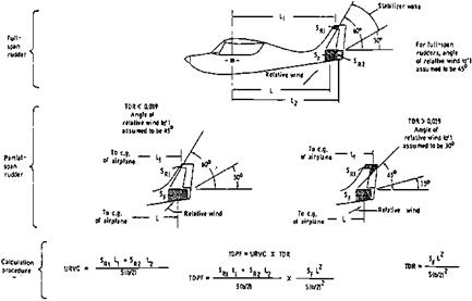
Simple preliminary design rules that would increase the chances for an airplane to have satisfactory recovery characteristics from spins were an important product of the NACA spin tunnel group. Figure 9.4 reproduces the best-known set of preliminary design rules (Neihouse, Lichtenstein, and Pepoon, 1946). Two separate parameters are used. One

Design for Spin Recovery

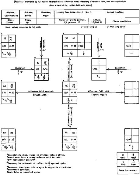
Figure 9.3 An example of the standardized spin recovery charts produced by the NASA Langley spin tunnel. The box locations correspond to control positions for the developed spin that precedes the recovery attempt. Blanks generally correspond to control positions for which the model would not spin. This particular chart is for the Grumman OV-1 Mohawk Army observation airplane. (From Lee, NASA TN D-1516, 1963)

is called TDR, the tail damping ratio, affecting whether the steady spin is steep or flat. The other is called URVC, the unshielded rudder volume coefficient, based on the rudder areas nominally out of the horizontal tail wake and their moment arms. The product of the two parameters is the tail damping power factor, or TDPF.

The 1946 TDPF design rules are a modification of a Royal Aircraft Establishment (RAE) criterion by E. Finn. Both the RAE and NACA criteria are based on empirical results, grounded in the flight mechanics of spins. For example, the TDR rule specifies a minimum

Design for Spin Recovery

Figure 9.4 Method of applying the 1945 Neihouse/Lichtenstein/Pepoon tail design requirements for satisfactory spin recovery, a controversial standard because it neglects factors otherthan the tail. (From Stough, Patten, and Sliwa, NASA TP 2644, 1987)

fuselage area under the horizontal tail for the spin to be normal, and not the flat, high-rotation – rate variety. At spin attitudes, that is, at high angles of attack and large yawing velocities, that particular area should indeed develop high static pressures and a considerable yawing moment resisting the spin rate, or damping the spin.

The 1946 NACA TDPF design rules were followed one year later by design rules drawn up specifically for personal-owner-type airplanes (Figure 9.5). The 1947 NACA TDPF rules use a 60-airplane subset of the 100 airplanes on which the 1946 rules are based. Both sets of tail design rules are considered to be a useful guide for airplanes with the general layout and weight distribution of that period in aeronautics. This includes propeller-driven general – aviation airplanes of the present day, so it is a source of wonder and alarm that these rules are ignored by many modern designers.

On the other hand, James S. Bowman, Jr., recently retired from NASA, points to cases in which light airplane configurations that satisfy the 1947 TDPF criterion have unsatisfactory spin recovery characteristics, weakening the case for applying the criterion to present-day airplanes. This is further discussed in Section 9.11, “The Break With the Past.”