Category Dynamics of. Atmospheric Flight

THE DERIVATIVE C

By contrast with C, the derivative G^, known as the dihedral effect, is of paramount importance. We have already noted its relation to roll stiffness and to the tendency of airplanes to fly with wings level. The primary con­tribution to Ct is from the wing—its dihedral angle, aspect ratio, and sweep all being important parameters.

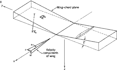
The effect of wing dihedral is illustrated in Fig. 8.7. With the coordinate system shown, the normal velocity component Vn on the right wing panel (R) is, for small dihedral angle Г,

Vn = w cos Г + v sin Г = w + г>Г

and that on the other panel is w — «Г. The terms ±vT/V = ±/?Г represent opposite changes in the angle of attack of the two panels resulting from sideslip. The “upwind” panel has its angle of attack and therefore its lift increased, and vice versa. The result is a rolling moment approximately Unear in both /? and Г, and hence a fixed value of 0^ for a given Г. This part of Gt is essentially independent of wing angle of attack so long as the flow remains attached.
THE DERIVATIVE C
Vn = normal velocity of panel R — w cos Г + v sin Г = ад + vP

vV VBT n

/. Aa of R due to dihedral === •*—■ = ——— = /5Г

THE DERIVATIVE C

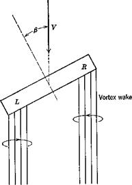
Even in the absence of dihedral, a flat lifting wing panel has a Ct pro­portional to CL. Consider the case of Fig. 8.8. The vertical induced velocity (downwash) of the vortex wake is greater at L than at R simply by virtue of the geometry of the wake. Hence the local wing angle of attack and lift are less at L than at R, and a negative Gt results. Since this effect depends, essentially linearly, on the strength of the vortex wake, which is itself proportional to the wing CL, then the result is ДGt^ oc CL.

THE f} DERIVATIVES (C,,f C,,f C„,, CAr)

The sideslip derivatives are all obtainable from static wind-tunnel tests on yawed models. Generally speaking, estimation methods are not very reliable, and testing is needed for accurate results.

THE DERIVATIVE C„„

“p

We shall assume that the thrust vector remains in the xz plane, so that it does not contribute to the Y force. Then in terms of Gc and CD (see Fig. 4.5) we have

Подпись: <4,= Подпись: d£a dp Подпись: (8.6,1)

where Pe, the equilibrium value, is zero. Hence

The main contributions to Cc usually come from the body and the tail, the wing contribution being minor. That from the tail is readily estimated. From (8.1,3) we have

(MU =

-Gt? V2Sf Lf 2

and

(4U =

-Gt 8-*

Lf s

whence

(^s^)tail

SFdCLp _ S dp

sF / — % 1 s

da

~dp)

(8.5,2)

The CD term of (8.6,1) would often be small compared to the tail contribution

(8.5,2) , and the whole derivative Gyoften has negligible effect on the vehicle dynamics.

AILERON REVERSAL

There is an important aeroelastic effect on roll control by ailerons that is significant on most conventional airplanes at both subsonic and supersonic speeds. This results from the elastic distortion of the wing structure associated with the aerodynamic load increment produced by the control. As illustrated in Fig. 6.22, the incremental load caused by deflecting a control flap at subsonic speeds has a centroid somewhere near the middle of the wing chord. At supersonic speeds the control load acts mainly on the deflected surface itself, and hence has its centroid even farther to the rear. If this load centroid is behind the elastic axis of the wing structure, then a nose-down twist of the main wing surface results. The reduction of angle of attack corresponding to <5 > 0 causes a reduction in lift on the surface as compared with the rigid case, and a consequent reduction in the control effectiveness. The form of the variation of Cld with JpF2 for example can be seen by considering an idealized model of the phenomenon. Let the aerodynamic torsional moment resulting from equal deflection of the two ailerons be T(y) oc lpV2da and let T(y) be antisymmetric, T(y) = —T(—y). The twist distribution corre­sponding to T(y) is в(у), also antisymmetric, such that 0(y) is proportional to T at any reference station, and hence proportional to %pV2da. Finally, the antisymmetric twist causes an antisymmetric increment in the lift distribution, giving a proportional rolling moment increment ДО, = 7c|p V2Sa. The total rolling moment due to aileron deflection is then

AO, = (0,JrigiA + HpV% (8.4,1)

and the control effectiveness is

As noted above, (Cl6 )rlftid is negative, and 1c is positive if the centroid of the aileron-indnced lift is aft of the wing elastic axis, the common case. Hence I Cl6 I diminishes with increasing speed, and vanishes at some speed VR, the aileron reversal speed. Hence

o = (%ie*+4pVR2

Wi

(8.4,3)

Substitution of (8.4,3) into (8.4,2) yields

Gha ^ ~

(8.4,4)

This result, of course, applies strictly only if the basic aerodynamics are not Mach-number dependent, i. e. so long as VR is at a value of M appreciably below 1.0. Otherwise к and (CV )rigid are both functions of M, and the equation corresponding to (8.4,4) is

Подпись: (8.4,5)% № = (cyrigid(M)

where Мд is the reversal Mach number.

It is evident from (8.4,4) that the torsional stiffness of the wing has to be great enough to keep VR appreciably higher than the maximum flight speed if unacceptable loss of aileron control is to be avoided.

ROLLING CONTROL

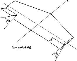
The angle of bank of the airplane is controlled by the ailerons. The primary function of these controls is to produce a rolling moment, although they frequently introduce a yawing moment as well. The effectiveness of the ailerons in producing rolling and yawing moments is described by the two control derivatives dCljdba and dCJdda. The aileron angle 6a is defined as the mean value of the angular displacements of the two ailerons. It is positive when the right aileron movement is downward (see Fig. 8.5). The derivative dCJdda is normally negative, right aileron down producing a roll to the left.

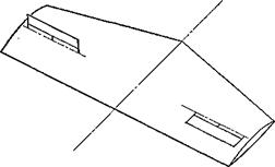
For simple flap-type ailerons, the increase in lift on the right side and the decrease on the left side produce a drag differential which gives a positive (nose-right) yawing moment. Since the normal reason for moving the right aileron down is to initiate a turn to the left, then the yawing moment is seen to be in just the wrong direction. It is therefore called aileron adverse yaw. On high-aspect-ratio airplanes this tendency may introduce decided diffi­culties in lateral control. Means for avoiding this particular difficulty include the use of spoilers and Frise ailerons. Spoilers are illustrated in Fig. 8.6. They achieve the desired result by reducing the lift and increasing the drag on the side where the spoiler is raised. Thus the rolling and yawing moments

ROLLING CONTROL

Fig. 8.5 Aileron angle.

developed are mutually complementary with respect to turning. Frise ailerons (Fig. 6.23) diminish the adverse yaw or eliminate it entirely by increasing the drag on the side of the upgoing aileron. This is achieved by the shaping of the aileron nose and the choice of hinge location. When deflected upward, the gap between the control surface and the wing is increased, and the relatively sharp nose protrudes into the stream. Both these geometrical factors produce a drag increase.

ROLLING CONTROL

ROLLING CONTROL

Section through spoiler

The deflection of the ailerons leads to still additional yawing moments once the airplane acquires a roll rate. These are caused by the altered flow about the wing and tail. These effects are discussed in Sec. 8.6 (Gn ), and are illustrated in Figs. 8.12 and 8.15.

A final remark about aileron controls is in order. They are functionally distinct from the other two controls in that they are rate controls. If the airplane is restricted only to rotation about the wind axis, then the appli­cation of a constant aileron angle results in a steady rate of roll. The elevator and rudder, on the other hand, are displacement controls. When the airplane is constrained to the relevant single-axis degree of freedom, a constant deflection of these controls produces a constant angular displacement of the airplane. It appears that both rate and displacement controls are acceptable to pilots.

ROLL STIFFNESS

ROLL STIFFNESS

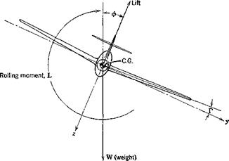
Consider a vehicle constrained, as on bearings in a wind tunnel, to one degree of freedom-rolling about the * axis. The forces and moments resulting from a fixed displacement ф are fundamentally different in character from those associated with the rotations a and /? about the other two axes. In the first place if the x axis coincides with the velocity vector V, no aerodynamic change whatsoever follows from the fixed rotation ф (see Fig. 8.4). The aerodynamic field remains symmetrical with respect to the plane of symmetry, the resultant aerodynamic force remains in that plane, and no changes occur in any of the aerodynamic coefficients. Thus the roll stiffness Сц is zero in that case.

If the x axis does not coincide with V, then a second-order roll stiffness results through the medium of the derivative Ct . Let the angle of attack of the x axis be v. x (Fig. 4.4), then the velocity vector when ф = 0 is

Подпись: (8.3,1)V cos a. x 0

_F sin v. x_

After rolling through angle ф about Ox, the velocity vector is (cf. Sec. 4.5)

" V cos otx

V2 = L1(^)Y1 = V sin ctx sin ф (8.3,2)

V sin kx cos ф_

Thus the sideslip component is v = V sin ax sin ф, and the sideslip angle is (4.3.3)

Подпись: (8.3,3)ft — sin 1 — = sin 1 (sin a„ sin ф)

As a result of this positive /3, and the usually negative there is a restoring rolling moment Gl^§ i. e.

AGt = Glp sin-1 (sin ax sin ф)

(8.3,4 a)

For small atx, we get the approximate result

A Gt

and if ф also is small,

= Glf sin 1 (a* sin ф) = Clpax sin ф

(8.3,46)

AC; = С^а. хф

(8.3,4c)

The stiffness derivative for rolling about Ox is then from (8.3,4a)

dCi sin ax cos ф дф lP( 1 — sin2 a. x sin2 фf/2

(8.3,5a)

or for ax << 1,

dCt. _ ,

(8.3,56)

or for a. x, ф « 1

^0l*.

дф »

(8.3,5c)

Thus there is a roll stiffness that resists rolling if ax is >0, and would tend to keep the wings level. If rolling occurs about a wind axis, the stiffness is zero and the vehicle has no preferred roll angle. If a*<0, then the stiffness

is negative and the vehicle would roll to the position ф = 180°, at which point C = 0 and (7j < 0.

The above discussion applies to a vehicle constrained, as stated, to one degree of freedom. It should not be thought that the derivative С1ф so deduced should be introduced into the rolling moment equation (5.13,176)! The rolling moment we have discussed above arises solely from the aerodynamic effect of fj, and as such is already included in the term of the equation. The usefulness of the above point of view is that it helps one to understand the behavior of free motions that consist principally of rolling about an axis in the plane of symmetry.

Having shown above that airplanes have no first-order aerodynamic roll stiffness, it is worthwhile to digress at this point to show why they neverthe­less have an inherent tendency to fly with wings level. They do so because of a secondary effect, involving gravity and Gt. When rolled to an angle ф, there is a weight component mg sin ф in the у direction (Fig. 8.4). This induces a sideslip velocity to the right, with consequent /3 > 0, and a rolling moment that tends to bring the wings level. The rolling and yawing motions that result from such an initial condition are however strongly coupled, so no significant conclusions can be drawn about the behavior except by a dynamic analysis (see Chapter 9).

YAW CONTROL

In most flight conditions it is desired to maintain the sideslip angle equal to zero. If the airplane has positive weathercock stability, and is truly

YAW CONTROL Подпись: ddr r dsr Подпись: — arVr Подпись: (8.2,1)

symmetrical, then it will tend to fly in this condition. However, yawing moments may act upon the airplane as a result of unsymmetrical thrust (e. g. one engine inoperative), slipstream rotation, or the unsymmetrical flow field associated with turning flight. Under these circumstances, (i can be kept zero only by the application of a control moment. The control that provides this is the rudder. Another condition requiring the use of the rudder is the steady side-slip, a maneuver sometimes used, particularly with light aircraft, to increase the drag and hence the glide path angle. From (8.1,2 and 5), the rate of change of yawing moment with rudder deflection is given by

This derivative is sometimes called the “rudder power.” It must be large enough to make it possible to maintain zero sideslip under the most extreme conditions of asymmetric thrust and turning flight.

A second useful index of the rudder control is the steady sideslip angle which could he maintained by a given rudder angle if the aileron angle, roll rate, and yaw rate were all zero. The total yawing moment would then be

Подпись: (8.2,2)Подпись:+ Сщдг

For steady motion, Gn = 0, and hence the desired ratio is

»r СПй

The rudder hinge moment and control force are treated in a manner similar to that employed for the elevator. Let the rudder hinge-moment coefficient be given by

Cftr = 4" Ьфг (8.2,4)

The rudder pedal force will then be given by

P = G? V*Srcr(b1*F+b2dr)

A

= G? VSMhl-P + a) + 6A)] (8.2,5)

A.

where G is the rudder system gearing.

The effect of a free rudder on the yaw stiffness is found by setting Ghr = 0 in (8.2,4). Then the rudder floating angle is

Подпись: (8.2,6)^free = –r<*F

b2

YAW CONTROL

The vertical-tail lift coefficient with rudder free is found from (8.1,2) to be

Подпись: aFa-F(8.2,7)

The free control factor for the rudder is thus seen to be of the same form as that for the elevator (see Sec. 6.6) and to have a similar effect.

YAW STIFFNESS (WEATHERCOCK STABILITY)

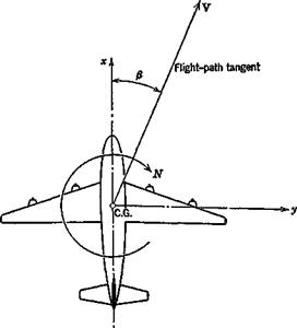
By exactly the same argument as used for pitch stiffness (Sec. 6.2), we conclude that flight vehicles should have positive yaw stiffness, i. e. (see Fig. 8.1) dCJdfi > 0. For then a perturbation in /3 will produce a restoring moment N that tends to keep the velocity vector in the plane of symmetry.

YAW STIFFNESS (WEATHERCOCK STABILITY)

Fna. 8.1 Sideslip angle and yawing moment.

YAW STIFFNESS (WEATHERCOCK STABILITY)

СПр is found from wind-tunnel measurements of the yawing moment, or when these are not available, can be estimated by synthesising the contri­butions of the various components of the vehicle. The principal contributions are those of the body and the tail. By contrast with Cm, the wing makes a relatively small contribution to (7n.

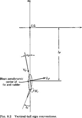
In Fig. 8.2 are shown the relevant geometry and the lift force LF acting on the vertical tail surface. If the surface were alone in an airstream, the velocity vector Yf would be that of the free stream, so that (cf. Fig. 8.1) <xF would be equal to —/?. When installed on an airplane, however, changes in both magnitude and direction of the local flow at the tail take place. These changes may be caused by the propellor slipstream, and by the wing and fuselage when the airplane is yawed. The angular deflection is allowed for by introducing the sidewash angle a, analogous to the downwash angle є. a is positive when it corresponds to a flow in the у direction: i. e. when it tends to increase olf. Thus the angle of attack is

*F=~P + o (8.1,1)

and in the linear case the lift coefficient of the vertical-tail surface is

CLr = <*,(-/? + a) + aA (8-1,2)

The lift is then

lf = GLf V2SF (8.1,3)

Just as with the horizontal tail, any difference between VF and V is absorbed into the coefficients aF and ar. The yawing moment is

nf = – cLf£v*sfif

whence C„F = – CLf (8.1,4)

isb

The ratio SFlFjSb is analogous to the horizontal-tail volume ratio, and is therefore called the vertical-tail volume ratio, denoted here by Vv. Equation

(8.1,4) then reads

0„ = – VvCLf (8.1,5)

and the corresponding contribution to the weathercock stability is

YAW STIFFNESS (WEATHERCOCK STABILITY)

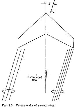
The Sidewash Factor do/df}. Generally speaking the sidewash is difficult to estimate wdth engineering precision. Suitable wind-tunnel tests are required for this purpose. The contribution from the fuselage arises through its behavior as a lifting body when yawed. Associated with the side force that develops is a vortex wake which induces a lateral-flow field at the tail. The sidewash from the propeller is associated with the side force which acts upon it when yawed, and may be estimated by the method of ref. 7.3, previously cited in Sec. 7.3. The contribution from the wing is associated with the asymmetric structure of the flow that develops when the airplane is yawed. This phenomenon is especially pronounced with low-aspect-ratio swept wings. It is illustrated in Fig. 8.3.

The Velocity Ratio VF/V. When the vertical tail is not in a propeller slipstream, VF/V is unity. When it is in a slipstream, the effective velocity increment may be dealt with as for a horizontal tail (see Sec. 7.3).

YAW STIFFNESS (WEATHERCOCK STABILITY)

Contribution of Propeller Normal Force. The yawing moment produced by the normal force which acts on the yawed propeller is calculated in the same way as the pitching-moment increment dealt with in Sec. 7.3. The result is similar to (7.3,10)

nv __ ^v 30Np /g j

dp b S dap ‘

This is known as the propeller fin effect, and is negative, i. e. destabilizing, when the propeller is forward of the C. G., but is usually positive for pusher propellers.

Lateral aerodynamic characteristics

CHAPTER 8

In the preceding two chapters we have discussed the aerodynamic character­istics of symmetrical configurations flying with the velocity vector in the plane of symmetry. As a result the only nonzero motion variables were V, a, and q, and the only nonzero forces and moments were T, D, L, and M. We now turn to the cases in which the velocity vector is not in the plane of symmetry, and in which rolling and yawing motions ((?, p, r) are present. The associated force and moment coefficients are Cc or Cy, Gp and Gn (see Table 5.1).

One of the simplifying aspects of the longitudinal motion is that the rotation is about one axis only (the у axis), and hence the rotational stiffness about that axis is a very important criterion for the dynamic behavior. This simplicity is lost when we go to the lateral motions, for then the rotation takes place about two axes (x and z). The moments associated with these rotations are cross-coupled, i. e. roll rotation p produces yawing moments Gn as well as rolling moment Gv and yaw displacements /3 and rate r both produce rolling and yawing moments. Furthermore, the roll and yaw controls are also often cross-coupled—deflection of the ailerons can produce significant yawing moments, and deflection of the rudder can produce significant rolling moments.

Another important difference between the two cases is that in “normal” flight—i. e. steady rectilinear symmetric motion, all the lateral motion and

force variables are zero. Hence there is no fundamental trimming problem— the ailerons and rudder would be nominally undeflected. In actuality of course, these controls do have a secondary trimming function whenever the vehicle has either geometric or inertial asymmetries—e. g. one engine off, or multiple propellers all rotating the same way. Because the gravity vector in normal flight also lies in the plane of symmetry, the C. G. position is not a dominant parameter for the lateral characteristics as it is for the longitudinal. Thus the C. G. limits, as discussed in Sec. 7.6 are governed by considerations deriving from the longitudinal characteristics.

SUMMARY OF THE FORMULAE

The formulae that are frequently wanted for reference are collected in Table 7.1. Where an entry in the table shows only a tail contribution, it is not implied that wing and body effects are not important, but only that no convenient formula is available.

FORCES ON THE WING

The vertical velocity of the wing section distant у from the center fine is

z = h(y)zT (7.13,2)

and the corresponding change in wing angle of attack is

A«(») = Цу)&тІГ (7.13,3)

This angle-of-attack distribution can be used with any applicable steady-flow wing theory to calculate the incremental local section lift. (It will of course be proportional to z^/F.) Let it be denoted in coefficient form by C’l(y)zT/V, and the corresponding increment in wing total lift coefficient by Cxio^y/F. G’t(y) and C’Lw are thus the values corresponding to unit value of the non­dimensional quantity zr/F.

FORCE ON THE TAIL

The tail experiences a downward velocity h(0)zT, and also, because of the altered wing lift distribution, a downwash change (dejdzT)zT. Hence the net change in tail angle of attack is

Aoq = h(0)zTIV—————— — zT

FORCES ON THE WING Подпись: (7.13,4)

dzT

FORCES ON THE WING Подпись: (7.13,5)

This produces an increment in the tail lift coefficient of amount

THE DERIVATIVE Ц

ZT

Подпись: and hence FORCES ON THE WING FORCES ON THE WING Подпись: (7.13,6)

This derivative describes the contribution of wing bending velocity to the lift acting on the airplane. A suitable nondimensional form is dCLjd(zTjV):

THE DERIVATIVE An

nct

This derivative (see 5.12,12) represents the contribution to the generalized force in the bending degree of freedom, associated with a change in the angle of attack of the airplane. A suitable nondimensional form is obtained by defining

n — З’

* ipv2s

Then the appropriate nondimensional derivative is.

Let the wing lift distribution due to a perturbation oc in the angle of attack (constant across the span) be given by Сг^(у)а. Then in a virtual displacement in the wing bending mode bzT, the work done by this wing loading is

rb/2

Подпись: bW— a G,(y)h(y) bzTpV{y) dy

FORCES ON THE WING

J-b/2

The tail also contributes to this derivative. For the tail lift associated with a is

Подпись: 4-э* >rce during tl ?£Ha

and the work done by this force during the virtual displacement is

Подпись: bzn3e

Therefore the contribution to G *• is and to is

^ a

The total value of Cis then the sum of (7.13,7 and 8.)

THE DERIVATIVE b,, (SEE 5.12,12)

This derivative identifies the contribution of zT to the generalized aero­dynamic force in the distortion degree of freedom. We have defined the associated wing load distribution above by the local lift coefficient С[(у)гт1У. As in the case of the derivative An above, the work done by this loading is calculated, with the result that the wing contributes

эсу _ 1 d2W

d(zT/V) ipV28 dzT d(zT/V)
f Gi(y)h(y)c(y) dy (7.13,9)

8 J-D/2

Подпись: -О,|*Л(0)[А«» Подпись: —1 d(zTiv)j Подпись: (7.13,10)

Likewise, the contribution of the tail is calculated here as for Anx, and is found to be

The total value of dC^jd{zTjV) is then the sum of (7.13,9 and 10.).