Category Dynamics of. Atmospheric Flight

GENERAL THEORY OF STATIC LONGITUDINAL STABILITY

The concept of static stability was introduced in Chapter 3, where it was identified with the nature of the exponential characteristic modes (Figs. 3.6a and b). In Sec. 3.3 (p. 70) it was pointed out that the vanishing of the constant term in the characteristic equation of a linear/invariant system provides a boundary between asymptotic stability and static instability. This is the criterion that we discuss in this section, and relate to the stability criteria presented earlier in Chapter 6.

The characteristic equation [see (3.3,7)] is

|sl – A| = 0

and clearly the constant term is found by setting s = 0, i. e.

co = I —A|

The criterion for static stability is then

Подпись: (9.3,1)I—A| > 0

GENERAL THEORY OF STATIC LONGITUDINAL STABILITY

The application of this criterion is in principle straightforward for any of the linear/invariant systems (5.13,18 to 20) that describe the longitudinal and lateral motions. In the interests of deriving a simple usable analytical result, however, we shall treat the special case represented by (9.1,1), in which the equilibrium flight path is horizontal, and z derivatives are neglected. When I —A| is expanded we get

Since the factor outside the square brackets is always positive (CL. could not be <—2fi for any reasonable heavier-than-air vehicle) the stability criterion becomes

GENERAL THEORY OF STATIC LONGITUDINAL STABILITY(9.3,3)

When comparing (9.3,3) with the static stability criteria discussed in Chapter 6, a minor difference in basic assumptions must be noted. In the preceding development, it was specifically assumed that the thrust vector rotates wdth the vehicle when a is changed. In the development leading to (6.4,24) by contrast, there is an implicit assumption that the thrust provides no component of force perpendicular to V [see (6.4,18)]. It is this difference that leads to the presence of CD in (9.3,3) whereas there is no corresponding term in the numerator of (6.4,24). Had the assumptions been the same, the expressions would be strictly compatible. In any case, °De is usually small compared to CL so that the difference is not important. We see that the justification for the statement made in Sec. 6.4, that the slope of the elevator trim curve (ddetrimldf)^ is a criterion of static stability, is provided by (9.3,3). [Note that CWf = CLe in (9.3,3).]

Another stability criterion referred to in Chapter 6 is the derivative dCmjdCL (6.3,21). It was pointed out there that this derivative can only be said to exist if enough constraints are imposed on the independent variables a, f, de, q, etc., on which Gm and CL separately depend. Such a situation results if we postulate that the vehicle is in rectilinear motion (q = 0) at constant elevator angle and throttle setting, with L = W, but wdth varying speed and angle of attack. Such a condition cannot, of course, actually occur in flight because the pitching moment could be zero at only one speed, but it can readily be simulated in a wind tunnel where the model is restrained by a balance. [The argument that follows is quite similar to that of (6.4,18) et seq.] With the above stipulations, Gm and CL reduce to functions of the

two variables V and a, and incremental changes from a reference state ( are given by

Подпись: (9.3,4)dCL = Cr da + 0LdV

dOm — da + Cmy dV

GENERAL THEORY OF STATIC LONGITUDINAL STABILITY GENERAL THEORY OF STATIC LONGITUDINAL STABILITY Подпись: (9.3,5)

The required derivative is then

provided dV/da exists. This is guaranteed by the remaining condition imposed, i. e. L — W (implying aT = 0). For then we have

W = 0L(a, t)ipV2S = const

from which we readily derive

(CLx da + CLy dV)yV*S + CLePVeS dV = 0 (9.3,6)

From (9.3,6)

Подпись: or Подпись: dV da Подпись: Or GENERAL THEORY OF STATIC LONGITUDINAL STABILITY Подпись: (9.3,7)

{CLv + 2CLJ dV + CLa da = 0

Подпись: dOr, dCr Подпись: L=W GENERAL THEORY OF STATIC LONGITUDINAL STABILITY Подпись: (9.3,8)

After substituting (9.3,7) into (9.3,5) and simplifying we get

On comparing (9.3,8) with (9.3,3), again neglecting 0D thereinfor compatibil­ity of assumptions, and noting that Gw = ОL, we see that the static stability criterion is

dP

Подпись: dOT<0 (9.3,9)

L=W provided that dCmldCL is calculated with the constraints A(Se = Дтг = q = 0 and L = W. [The quantity on the left side of (9.3,8) and (9.3,9) is sometimes referred to as speed stability in the USA, by contrast with “angle of attack” stability. In Great Britain, this term usually has a different meaning, as in Sec. 11.5.]

Подпись: dCKr dOr GENERAL THEORY OF STATIC LONGITUDINAL STABILITY Подпись: (9.3,10)

On using the definition of hs given in (6.4,26) we find from (9.3,8) that

i. e. that it is proportional to the “stability margin,” and when CLT < 2GLe’ is equal to it.

Finally, we must check on the significance of the “pitch stiffness” parameter Gmx, to which great importance was attached in Chapter 6. We see from

9.3,3 that when 0Ly and Cmy are zero, Cm < 0 does indeed provide an exact criterion for static stability. Even when CLy and Gm are not zero, we shall see from the examples to follow that Cma < 0 is still a useful and significant criterion.

This also is compared with exact results in the figures that follow. SHORT-PERIOD MODE

Figure 9.26 shows that the speed remains substantially constant in the short-period mode, and this suggests an approximation to the equations in which = 0. Again, one equation must be dropped from the set, and the correct choice is the speed equation of motion. The reduced equations are

Подпись: then, after neglecting the same derivatives as before, Подпись: (9.2,12)

The characteristic equation is then

Подпись: — s

(CLa+CDe)

Подпись: = 0 (9.2,13)

* Ifi Cm<SpLa + ! JL (/7 – L П ) _ s

r, r——————- ^—j iX ”*‘+

This expands to give the cubic equation

Подпись: where This also is compared with exact results in the figures that follow. SHORT-PERIOD MODE Подпись: _ + OmjpLg + Cp) 2fitv IV№LX + CD) — 2ц(Ст^ + СтЛ) 2цїу Подпись: (9.2,14)

S(s2 + Cxs + c0) = 0

of which the second-degree factor is the approximation for the short-period roots. The zero root is of no interest. With the numerical values of the preceding example, the roots obtained from (9.2,14) are

A = -.1162 x 10-1 ± .1892 x 10-1 і

which are to be compared to the exact values

-.1161 x 10-1 ± .1891 X 10-4

The errors are seen to he very small, less than to % in both the damping and the period. Equations (9.2,14) give a good approximation to the im­portant short-period oscillation over a wide range of flight and vehicle parameters.

Because of the large influence of C. G. position on Cm, a critical C. G. position is indicated by (9.2,14) when

+ Cmg(CLa + CDe) = 0 (9.2,15)

At this condition, c0 vanishes, and the characteristic equation becomes

«(* + сг) = 0

Подпись: or Подпись: crit This also is compared with exact results in the figures that follow. SHORT-PERIOD MODE Подпись: (9.2,16)

with roots X = 0, — cv The latter corresponds to a damped exponential mode, and the zero root identifies one that is a constant state in the two variables Да and q. This state, a longitudinal motion at constant speed, а and q is none other than the steady pull-up treated in Sec. 6.10. The critical C. G. position is found from (9.2,15) thus

Comparison of (9.2,16) and (6.10,8) shows that hceii above would be exactly hm (the control-fixed maneuver point) if CDe were zero in the former and CL^ zero in the latter. In fact these equations both describe the same flight condition, and the differences between them are entirely due to differences in the detailed assumptions made in their derivations. Specifically, CLq was neglected in (9.2,12) and no component of the thrust normal to V was included in the derivation of (6.10,8). Had the assumptions been strictly compatible, the results would have been identical.

The above analysis shows that the steady pull-up at constant speed can occur without motion of the controls at this C. G. position, and hence it is indeed the condition of zero control motion per g. We can further deduce that movement of the C. G. farther aft causes a reversal of sign of e0 and hence corresponds to a ‘‘static instability” as in a mass-spring-damper with a “negative” spring. In this light the control-fixed maneuver point is seen as a criterion for the divergence of the short-period mode.

PHUGOID MODE

Lanchester’s (ref. 1.1) original solution for the phugoid used the assumptions that Да = 0 and T — D = 0. It follows that there is no net aerodynamic force tangent to the flight path, and hence no work done on the vehicle except by gravity. The motion is then one of constant total energy, as suggested previously. This simplification makes it possible to treat the most general case with large disturbances in speed and flight-path angle (see Miele, ref. 1.7, p. 271 et seq.). Here we content ourselves with a treatment of only the corresponding small-disturbance ease, for comparison with the exact numerical result given earlier. The energy condition is

E = m, V2 — mgzB — const

or V2 = V2 + 2 gzE (9.2,1)

where the origin of FE is so chosen that V = Ve when zE — 0. With а. constant, and in addition neglecting the effect of q on CL, then CL is constant at the value for steady horizontal flight, i. e. CL = CL — Cw, and L = CweipV2>S or, in view of (9.2,1),

L = CWeip V2S + (CWepgS)zE =W+kzE (9.2,2)

Thus the lift is seen to vary linearly with the height in such a manner as
always to drive the vehicle back to its reference height, the “spring constant” being

* = CWJPgS (9.2,3)

The equation of motion in the vertical direction is clearly, when T — D — 0,

Подпись: or for small в, PHUGOID MODE Подпись: (9.2,4)

W — L cos в = mz,

On combining (9.2,2) and (9.2,4) we get

mzE + kzE = 0

which identifies a simple harmonic motion of period

T = 2w /— = 2tt

& V Gw. P9^

Since Gw = mg/lpVe2S, this becomes

Подпись: (9.2,5)T = чгл/2-

a beautifully simple result, suggesting that the phugoid period depends only on the speed of flight, and not at all on the airplane or the altitude! For the above example, Ve — 733 fps, and (9.2,5) gives T = 101 sec, a value 12.2 % different from the correct result, 115 sec.

Although (9.2,5) is a very useful result for the period, the above theory cannot give any information at all about the damping, since thrust and drag were eliminated from consideration and it is precisely these that cause the amplitude of the oscillation to change. For a better approximation, we return to the equations of motion and incorporate a simplification suggested by Fig. 9.2», i. e. Да = 0. Note that this is one of Lanchester’s two assumptions. If we drop one variable, we must also drop one equation of motion. Now the zero Да may be considered to imply zero pitching moment of inertia, so that pitch equilibrium is always maintained throughout the motion, and this suggests that it is the pitching moment equation that should be dropped. With Да and the Cm equation missing, (9.1,1) reduces to

(9.2,6)

For consistency with the previous numerical example, we neglect as well the derivatives CLp, CDp, CLq, CL^. Now the second of the three equations is an algebraic relation, i. e. with the preceding approximations

PHUGOID MODE

332 Dynamics of atmospheric flight The “undamped” period is seen to be

Подпись: 2 V 2 7Г m c

GWe ‘ PS(cl2) ‘ 2Ve

After eliminating GWc this reduces exactly to (9.2,5) so that the Lanchester result is recovered from (9.2,9) when CTy = 0.

PHUGOID MODE

For the case of horizontal flight under consideration here, GTp depends only on the reference drag coefficient and the type of propulsion system (see Sec. 7.8). For the example airplane in horizontal flight CTp —2GD, and in that case the damping coefficient is

To this approximation, £ will always vary inversely as the (L/D) ratio, but for constant-power propulsion (instead of constant thrust) the constant is 3/2V2 (instead of 1/V2).

The accuracy of the approximation given by (9.2,9) is illustrated on Figs. 9.4a, 9.8, and 9.16.

Подпись: (9.2,11)
PHUGOID MODE

Another approximation that gives better results for the period, but not necessarily for the damping, is one originally due to Bairstow (ref. 1.4) [the derivation is given by Ashkenas and McRuer (ref. 9.5)]. When converted to the notation of this work, it gives

APPROXIMATE EQUATIONS FOR THE LONGITUDINAL MODES

It is frequently useful and desirable to have approximate analytical expressions for the periods and dampings of the characteristic modes. These are convenient for assessing the influence of the main flight and vehicle parameters that affect the modes, and are especially useful when con­ventional methods of servomechanism analysis are applied to automatic control systems (ref. 9.4). There are two approaches generally used to arrive at these approximations. One is to write out a literal expression for the characteristic equation and, by studying the order of magnitude of the terms in it, to arrive at approximate linear or quadratic factors. For example, if the characteristic equation

•S’4 + %S’3 -(- c2s2 + crs c0 = 0

is known to have a “small” real root, an approximation to it may be obtained by neglecting all the higher powers of s, i. e.

Cis + c0 = 0

Or if there is a “large” complex root, it may be approximated by keeping only the first three terms, i. e.

s2 + C3s + c2 = О

This method is frequently useful, and sometimes the only reasonable way to get an approximation.

The second method, which has the advantage of providing more physical insight, proceeds from a foreknowledge of the modal characteristics to arrive at approximate system equations of lower order than the exact ones. For the longitudinal modes we use the second method (see below), and for the lateral modes (see Sec. 9.6,1) both methods are needed.

It should be noted that no simple analytical approximations can be relied on to give accurate results under all circumstances. Machine solutions of the exact matrix is the only certain way. The value of the approximations is indicated by examples in the following.

To proceed now to the phugoid and short-period modes, we saw in Fig. 9.2 that some state variables are negligibly small in each of the two modes. This fact suggests certain approximations to them based on reduced sets of equations of motion. These approximations, which are quite useful, are developed below.

FLIGHT PATHS IN THE CHARACTERISTIC MODES

Additional insight into the modes is gained by studying the flight path. With the atmosphere at rest, the differential equations for the position of the C. G. in Fe are given by (5.13,19), with ye = 0, i. e.

Dxf = 1 – f – Д V

Dze = —(Д0 — Д«) (9-1,2)

In a characteristic oscillatory mode with eigenvalues A, A* the variations of ДТ, AO, and Да are [cf. (3.3,30)]

AV — и13е1 + и*/ *

Да = u2jeli + и*/*1 (9.1,3)

АО = щ3еи + и*3е1*1

where the constants ui} are the components of the eigenvector corresponding to A. For the previous numerical example, they are the complex numbers given in Table 9.2 with j — 1 for the phugoid and j = 3 for the short-period mode. After substituting (9.1,3) in (9.1,2) and integrating we get

Подпись: = t + 2e"*' Re zE = 2efd Re ~ Uii e!“‘J
FLIGHT PATHS IN THE CHARACTERISTIC MODES Подпись: (9.1,4)

&E = * + НГ eU + JTe ^ + COnst

where Re denotes the real part of the complex number in the square brackets. The dimensional coordinates are obtained by using the additional relations

xE — — xE, zE — — iE, t — t*t (9.1,5)

^ z

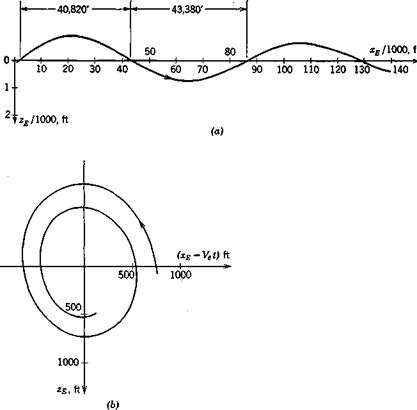
For the numerical data of the above example (9.1,4) and (9.1,5) have been used to calculate the flight paths in the two modes, plotted in Fig. 9.3. The magnitudes of the eigenvectors were chosen so that 0max is approximately 4° in the phugoid mode, and 10° in the short-period mode, t = 0 corresponds to the configuration of variables in Fig. 9.2, and the arbitrary constants of

(9.1,4) are zero. The latter choice makes the initial point of the flight paths differ from the origin, but they both approach the xE axis as t —> сю. Figure 9.3a shows that the phugoid is an undulating flight of very long wavelength.

FLIGHT PATHS IN THE CHARACTERISTIC MODES

Fie. 9.3 (о) Phugoid flight path (fixed reference frame). (6) Phugoid flight path

(moving reference frame), (c) Short-period flight path.


FLIGHT PATHS IN THE CHARACTERISTIC MODES

Since Да = 0, the vehicle “flies like an arrow,” i. e. has its x axis approxi­mately tangent to the trajectory. The mode diagram, Fig. 9.2a shows that the speed leads the pitch angle by about 90°, from which we can infer that V is largest at the bottom of the wave and least at the top. This variation in speed results in different distances being traversed during the upper and lower halves of the cycle, as shown in Fig. 9.3a. For larger amplitude oscil­lations, this lack of symmetry in the oscillation becomes much more pro­nounced (although the linear theory then fails to describe it accurately) until ultimately the upper part becomes first a cusp and then a loop (see Miele, ref. 1.7, p. 273). The motion (see Sec. 9.2) is approximately one of constant total energy, the rising and falling corresponding to an exchange between kinetic and potential energy. Figure 9.36 shows the phugoid motion relative to axes moving at the reference speed Ve. This is the relative path that would be seen by an observer flying alongside at speed Ve.

Figure 9.3c shows the path for the short-period mode. The disturbance is so rapidly damped that the transient has virtually disappeared within 1000 ft of flight, even though the initial Да and Д6 were very large. The deviation of the path from a straight line is small, the principal feature of the motion being the rapid rotation in pitch.

EIGENVECTORS

The eigenvectors corresponding to the above modes are given in the Table 9.2. They are not normalized, being to an arbitrary scale. The first and third columns correspond to w > 0, the second and fourth to 6) < 0.

Table 9.2

Eigenmatrix [w<#]

Phugoid

Short-Period

A

AV

-.227 x ЇЙ + .281 і

-.227 X 10-1 -.281 і

.279 X 10-2 + .180 x 10-2 г

.279 x 10-2 -.180 x 10-2г

Да

.639 х 1СГ3 -.629 х 10-Ч

.639 X 10~3 + .629 х 10-2 г

.333

+ .195 і

.333 -.195 і

Я

-.115 х 10-4 + .202 х 10-3 і

-.115 х 10-4 -.202 х 10-3І

-.455 x 10-2 + .578 X 10-2 і

-.455 x 10-2 -.578 x 10-2 г

де

.353

+ .116 X 10—2 І

.353

-.116 x 10-4

.329

+ .383 x 10_1 і

.329

-.383 x 10_1 і

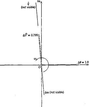
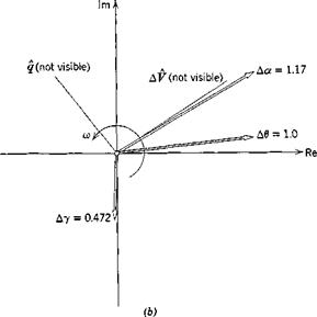
Figure 9.2 is the Argand diagram of the vectors in columns 1 and 3. This is a very effective form of displaying modal characteristics. Since the actual magnitudes of eigenvectors are arbitrary, only the relative lengths of the vectors are shown, taking that of А d = 1.0. The vectors shown can be imagined as rotating and shrinking (just as in Fig. 3.6e except that here we only have those with m positive); and their projections on the Re axis can be thought of as the real values of the indicated variables.

The phugoid is seen to be a motion in which the speed and pitch angle d are the main variables, the former leading the latter by roughly 90° in phase, while the angle of attack and the pitch rate remain virtuafiy constant at their reference values. The flight-path angle Ду is related to Ad and Act by

(5.10,22) , Ay = Ad — Ax, so that in the phugoid Ay = Ad, and the oscilla­tory flight-path angle lags the speed by about 90°.

In the short-period mode, by contrast, there is negligible speed variation, while the angle of attack oscillates with an amplitude and phase not much different from that of Ad. The difference vector Ay is also shown in the figure. This mode as well is one that proceeds essentially in two degrees of freedom, Да and Ad.

EIGENVECTORS

(а)

EIGENVECTORS

EIGENVALUES

Mode 1: 1 = -.3065 X lO"4 ± .573 X 10~3 *

Mode 2:1= -.1161 X 10-1 ± .1891 X 10-4

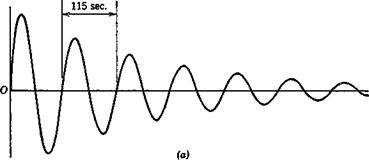
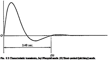
The corresponding periods and damping times are given in Table 9.1. We note that the phugoid mode is of long period (about 2 min) and lightly damped, whereas the short-period mode is quite rapid and very heavily damped. The characteristic transients of these two modes are shown in Pig. 9.1.

f Prepared by Dr. P. C. Hughes. It is perhaps indicative of the times that most of the digital computation needed for this and the following examples was performed, using these subroutines, by a high-school student, David Alexander Etkin.

Table 9.1

Mode

Name

Period

(sec)

fhalf

(sec)

-^half

(cycles)

1

Phugoid®

115

237

2.06

2

Short-period

3.48

.626

.18

EIGENVALUES
Подпись: FIG. 9.1 Characteristic transients, (a) Phugoid mode. (6) Short-period (pitching) mode.

a The phugoid mode was first described by Lanchester (ref. 1.1), who also named it. The name comes from the Greek root for flee as in fugitive. Actually Lanchester wanted the root for fly. Appropriate or not, the word phugoid has become established in aeronautical jargon.

APPROXIMATION

Many useful results and insights can be obtained using the flat-Earth approximation. As we showed in Chapter 5, this approximation is valid for a wide range of flight conditions. We begin with the longitudinal modes, for which the relevant small-disturbance equations in nondimensional form are (5.13,18 and 19). We shall consider first a subsonic transport airplane in a reference steady state of horizontal flight, (ye = 0) and initially neglect the 2 derivatives as well. This is an approximation that is almost universally made in dealing with the flight of airplanes at subsonic speeds. Its significance is explored in Sec. 9.4. Thus the relevant equations are (5.13,19) with ye = 0.

For this class of vehicle there is little error entailed by assuming that the inclination of the thrust vector, otT, is zero, and we make this assumption.

Since we are concerned with stability of a steady state, i. e. with autono­mous behavior, all the elements of the control vector—the last column on the r. h.s. of (5.13,19)—are zero as well. We are left then with an autonomous linear/invariant system with the matrix shown on the facing page.

The general theory for such systems has been given in Sec. 3.3, where it was pointed out that the central elements of the solutions for free motion are the eigenvalues and eigenvectors. To obtain the natural modes of a vehicle, subject to the approximations and restrictions implicit in (9.1,1), it then remains to assign numerical values to the elements of A and to calculate its eigenvalues and eigenvectors.

Numerical Example. The following data pertain to a hypothetical jet transport airplane flying at high altitude.

Подпись:60 psf

.000889 (approx. 30,000 ft altitude)

7 /л

.0105 sec C *

CD = .016 + —

7tt

It is assumed that the thrust of the jet engines does not vary with speed, i. e. 3TjdV = 0, and that there are no speed effects on the aerodynamic deri­vatives. The remaining data needed for (9.1,1) are given for this particular vehicle as (see Table 7.1)

0La = 4.88; Cmx=-<t.88(hn-h)-, (A„ – A) = .16 2C

GDa = ~~ GLx’’ GL& = = —4.20

®l, — 0; Oma = – 22.9; GTv=-2GTe=-2CDe CLr = CDy = Gmf = 0.

Using the above data, the coefficients of A were calculated, and the eigen­values and eigenvectors found by library subroutines’}- available for the UTIAS IBM 1130 computer. Let the eigenvalues be X — n і ico where the denotes nondimensional values (note that the independent variable of the differential equations is t = t/t*). The properties of interest are then, in real time:

Period, T = t* —

Подпись: half Подпись: —t Подпись: .69315 7І

ft)

-^half — ^half/^1

The results obtained are as follows:

Stability of steady flight

CHAPTER 9

The preceding chapters have provided the analytical and aerodynamic tools needed to analyze the dynamic behavior of flight vehicles. We now apply them to a consideration of the stability of small disturbances from steady flight. This is an extremely important property of aircraft—first, because steady flight conditions make up most of the flight time of airplanes, and second, because the disturbances in this condition must be small for a satisfactory vehicle. If they were not it would be unacceptable for either commercial or military use. The required dynamic behavior is ensured by design—by making the small-disturbance properties of concern (the natural modes, Fig. 3.6) such that either human or automatic control can keep the disturbances that ensue from atmospheric motion, movement of passengers, etc., to an acceptably small level. Finally, as pointed out in Sec. 5.10, the small-disturbance model is actually valid for disturbance magnitudes that seem quite violent to human occupants.

To study the stabihty of the linear/invariant systems that result from the small-disturbance approximation, we need only the eigenvalues of the system. If the real parts are negative, the system is stable. More complete information about the characteristic modes is usually wanted, however, and is supplied by the eigenvectors. The complete solution for arbitrary initial conditions in the autonomous case follows directly from the eigenvalues and eigen­vectors—it is given by any of (3.3,9), (3.3,13), or (3.3,49).

For the most part, the equations of motion are too complicated, even when linearized and simplified as far as is reasonable, to arrive at analytical results of general validity. Hence the technique we use is to demonstrate repre­sentative behavior by numerical examples. From these, certain useful analytical approximations can be inferred.

THE DERIVATIVE

The change in aileron hinge moment due to yawing velocity is a consequence of the velocity differential between the right and left ailerons. Let the hinge- moment coefficient of the right-hand aileron, at zero aileron angle, be СЫа. Then the corresponding hinge moment, with no yawing, is Ghao(pj2)V28aca. This hinge moment is normally balanced by that on the left aileron, so that no load is carried to the pilot’s control. Now, when yawing is added, the mean forward velocity at the right-hand aileron is changed from V to (F — rya), so that the hinge moment is approximately Cna(>(pj2)(V — гуа)2$аса. To the first order in r, the incremental hinge moment is

Д Ha = – ChaiipryaV8aca

On the left-hand side, the increment in H is equal to the above but opposite in sign, so that the two are additive with respect to the stick force, just as though the ailerons were deflected through a small positive angle. The coefficient of ДHa is

Art лр гУа____________________ У a rt

ha — ~ ~

Since Cha is defined as the hinge moment on one aileron then

Подпись: (8.7,6)rt лУа ft

°haT — + °ha0

Summary—Lateral Derivatives

Су

Cl

Cn

Cjia

chr

p

-e-f)

F 8 Ь dp}

*

Neg.

p

N. A.6

* / ^ 3cr aFVvy b 0a)

2?c4

a /2 — -"i 7"Ц 6 Эр/

r

* S*,/ l. jj, da

* &F Z_F_ /„ l_F j|f S b 6 + Sr)

/ сгЭ

—apVyl2 — + (tail) V I2

-2Cr y: p (iet)

4 6 °л“о

c /2— + —’і С7"Ц2 Ь +

8a

Neg. c

N. A.

N. A.

Chag

Neg.

8r

Sp –

ar s

S’jfi Zp

ar s T

—arFF

Neg.

Chrg

Table 8.1

a * denotes a contribution from the tail only.

Подпись: 3176 N. A. means no convenient formula available. c Neg. means usually negligible.

THE DERIVATIVE ChTr

The change in the vertical-tail angle of attack (8.7,1) induces a change in the rudder hinge moment. This is given by

THE DERIVATIVE

where Ghr is the derivative, with respect to the vertical-tail angle of attack of the rudder hinge-moment coefficient. Hence

c – = av(2T+l) <8V)

8.8 SUMMARY OF THE FORMULAE

Table 8.1 contains a summary of useful formulae used for estimation purposes.