Category Dynamics of. Atmospheric Flight

THE z DERIVATIVES (Сг., CA, Cw Cm)

There are two main classes of z derivatives; those that are associated with ground proximity, and those that are associated with vertical gradients in the properties of the atmosphere. Of the latter the density gradient is the most important, and others can probably be ignored most of the time.

We have described some of the effects of ground proximity in Sec. 7.5. To calculate the associated г derivatives one needs the data, either theoretical or experimental, on the variation of the various coefficients with height above ground. For configurations with large power effects, i. e. strong slipstreams or jets impinging on the ground, testing is generally required to get good results. The ground effects can be very large, and the z derivatives can exert a very important influence on the vehicle dynamics at landing and take-off.

As to the effects of atmospheric gradients, the gradient dpldz has already been explicity included in the equations of motion (5.13,16), so that if T, D, L, M all vary exactly as p when the speed is constant then CTz etc. will all be zero. This assumption is probably good enough for D, L, and M, but not always for T. If the vehicle uses air-breathing engines, then T cc pis reason­able, and CTz = 0; but if a constant-thrust rocket is used, then we have

dTjdz = 0, and from the analysis on p. 183,

Подпись: GПодпись: TZTHE z DERIVATIVES (Сг., CA, Cw Cm)(7.12,1)

Подпись: П Подпись: К Подпись: A l

The only other atmospheric gradients that might need to he included are those associated with Reynolds number Be and Mach number M. Sometimes, for very high altitudes the particulate nature of air becomes a factor. The Knudson number

where 1 is the mean free path and l is a characteristic length of the vehicle, may then be used as an aerodynamic parameter. It is not a new independent variable, being related to M and Re:

_M

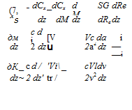
*„ = 1.267,- where у is the ratio of specific heats. For air a rough approximation is Kn M/Fe. The circumstances when these gradients might be important are those involving very rapid changes of the flow field with the parameter in question—for example, near M = 1, the variations of M with height due to sound-speed gradient; and near the Re for boundary layer transition. A typical derivative would be calculated thus. Let Gx stand for any of GT – • • Cm; then

Подпись:Подпись:(7.12,2)

where

THE z DERIVATIVES (Сг., CA, Cw Cm)
Подпись: Finally,

and

7.13 AEROELASTIC DERIVATIVES

In Sec. 5.12 there were introduced certain aerodynamic derivatives associated with the deformations of the airplane. These are of two kinds: those that appear in the rigid-body equations, and those that appear in the added equations of the elastic degrees of freedom. These are illustrated in

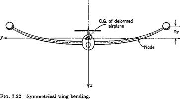
Подпись: = 0this section by consideration of the hypothetical vibration mode shown in Fig. 7.22. In this mode it is assumed that the fuselage and tail are rigid, and have a motion of vertical translation only. The flexibility is all in the wing, and it bends without twisting. The functions describing the mode (6.12,1) are therefore:

THE z DERIVATIVES (Сг., CA, Cw Cm)

у’ = У — Уо = 0 (7.13,1)

z’ = г — 20 = Цу)гт

For the generalized coordinate, we have used the wing-tip deflection zT. h(y) is then a normalized function describing the wing bending mode.

In view of the fact that the elastic degrees of freedom are only important in relation to stability and control when their frequencies are relatively low, approaching those of the rigid-body modes, then it is reasonable to use the same approximation for the aerodynamic forces as is used in calculating stability derivatives. That is, if quasisteady flow theory is adequate for the aerodynamic forces associated with the rigid-body motions, then we may use the same theory for the elastic motions.

In the example chosen, we assume that the only significant forces are those on the wing and tail, and that these are to be computed from quasisteady flow theory. In the fight of these assumptions, some of the representative derivatives of both types are discussed below. As a preliminary, the forces induced on the wing and tail by the elastic motion are treated first.

AERODYNAMIC TRANSFER FUNCTIONS

Finally, it should be remarked that there is no need to accept the small inaccuracy associated with the use of unsteady derivatives such as CL&, etc. In Sec. 5.11 it was shown how the use of aerodynamic transfer functions could avoid this difficulty entirely, and equations (5.14,1 to 3) were presented for this purpose. To obtain a transfer function from the indicial response, (5.11,6) can be applied. Thus if the step-function response of Fig. 7.17 is designated AL(t(t), then

®Za(S) — 6v^Za(‘S)

and similarly for all other transfer functions that appear in (5.14,1 to 3).

When the information available is in the form of a frequency-response analysis or measurement, then the transfer function can be obtained from it directly. From (3.4,25) we have the general relation for frequency response of a linear system in terms of the transfer function. Thus, let Gav(s) be the transfer function relating any aerodynamic coefficient Ca to any state variable v and Gav(ik) be the frequency-response vector giving Ga for periodic v. G(s) is obtained from G(ilc) by replacing ik by s, or к by —is.

CONTRIBUTIONS OF A TAIL

There is an approximate method for evaluating the contributions of a tail surface, which is satisfactory in many cases. This is based on the concept of the lag of the downwash. It neglects entirely the nonstationary character of the lift response of the tail to changes in tail angle of attack, and attributes the result entirely to the fact that the downwash at the tail does not respond instantaneously to changes in wing angle of attack. The downwash is assumed to be dependent primarily on the strength of the wing’s trailing vortices in the neighborhood of the tail. Since the vorticity is convected with the stream, then a change in the circulation at the wing will not be felt as a change in downwash at the tail until a time At — IJV has elapsed, where lt is the tail length (Fig. 6.10). It is therefore assumed that the instantaneous downwash at the tail, e(t), corresponds to the wing a at time (t — At). The corrections to the quasistatic downwash and tail angle of attack are therefore

Подпись: де lt — бі-да. V Де =——– a At

do.

CL& OF A TAIL

The correction to the tail lift coefficient for the downwash lag is

Подпись: = at Даг = aA *Подпись: (7.10,10)h де

V да

The correction to the airplane lift is therefore

* ~ Л deSt

AC r = a A ——— *

Подпись: and Подпись: (I) Подпись: де -2 atV„ — * H da. Подпись: (7.10,11)

VdaS

Cma OF A TAIL

Подпись: . де lt ~aja — 1.7 * да V H The correction to the pitching moment is obtained from ДCLt as Mm = – VHACLt

Подпись: ThereforedCm lt де

—- = —aA’jf———

Подпись: and Подпись: dC„ Подпись: = c oa Подпись: (7.10,12)

da Vda

OF A TAIL

The correction to at produces a change in the elevator hinge moment

Подпись: &Che = Ch Aat = Ch — a -p ' a< да V

Подпись: *4, da CONTRIBUTIONS OF A TAIL CONTRIBUTIONS OF A TAIL

де. lt

CONTRIBUTIONS OF A TAIL

THE a DERIVATIVES (CL„ Стл> QJ

The a derivatives owe their existence to the fact that the pressure dis­tribution on a wing or tail does not adjust itself instantaneously to its equilibrium value when the angle of attack is suddenly changed. The calculation of this effect, or its measurement, involves unsteady flow. In this respect, the oc derivatives are very different from those discussed previously, which can all be determined on the basis of steady-state aerodynamics.

CONTRIBUTIONS OF A WING

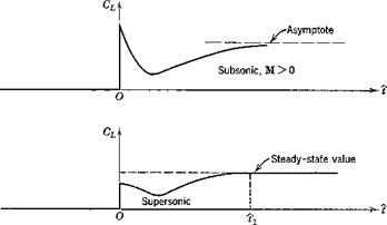
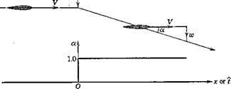
Consider a wing in horizontal flight at zero a. Let it be subjected to а downward impulse, so that it suddenly acquires a constant downward velocity component. Then, as shown in Fig. 7.17, its angle of attack undergoes a step increase. The lift then responds in a transient manner (the indicial response) the form of which depends on whether M is greater or less than 1.

THE a DERIVATIVES (CL„ Стл&amp;gt; QJ

THE a DERIVATIVES (CL„ Стл&amp;gt; QJ

THE a DERIVATIVES (CL„ Стл&amp;gt; QJ

Fig. 7.17 Lift response to step change in a. (After Tobak, N АСА Sept. 1188.)

In subsonic flight, the vortices which the wing leaves behind it can influence it at all future times, so that the steady state is approached only asymptot­ically. In supersonic flight, the upstream traveling disturbances move more slowly than the wing, so that it outstrips the disturbance field of the initial impulse in a finite time tv From that time on the lift remains constant.

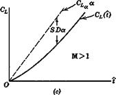
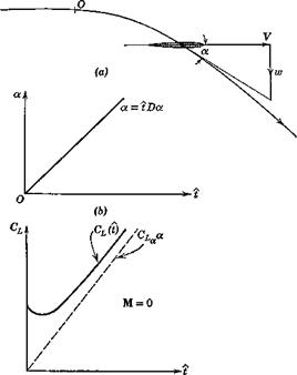
In order to find the lift associated with a, let us consider the motion of an airfoil with a small constant a, but with q = 0. The motion, and the angle of attack, are shown in Fig. 7.18. The method used follows that introduced by Tobak (ref. 7.12). We assume that the differential equation which relates CL(t) with a(t) is linear. Hence the method of superposition may be used to derive the response to a linear a(t). Let the admittance be A(t). Then, [cf. (5.11,2)], the lift coefficient at time і is

CL(і) = f A{i — r)a'(r) dr

Jt=0

THE a DERIVATIVES (CL„ Стл&amp;gt; QJ Подпись: I dr Подпись: (7.10,1)

Since oc'(t) = Dol — constant, then

The ultimate CL response to a unit-step a input is CL. Let the lift defect be/(f): i. e.

A(i) = CLx -f(t)

THE a DERIVATIVES (CL„ Стл&amp;gt; QJ

Then (7.10,1) becomes

Подпись: (7.10,2)— GT a — 8 Da.

J-‘Ct

where S(i) = ji=af(t — r) dr. The term 8 Da is shown on Fig. 7.18. Now, if the idea of representing the lift by means of aerodynamic derivatives is to be valid, we must be able to write, for the motion in question,

GL(t) = CLa(t) + GLDa (7.10,3)

where CL and CL& are constants. Comparing (7.10,2 and 3), we find that CL± = —S(i), a function of time. Hence, during the initial part of the motion, as already pointed out in Sec. 5.11 the derivative concept is invalid. However, for all finite wings,/ the area S(t) converges to a finite value as t increases indefinitely. In fact, for supersonic wings, 8 reaches its limiting value in a finite time, as is evident from Fig. 7.17. Thus (7.10,3) is valid,/ with constant

f For two-dimensional incompressible flow, the area S(t) diverges as t —>• со. That is, the derivative concept is definitely not applicable to that case.

X Exactly for supersonic wings, and approximately for subsonic wings.

THE a DERIVATIVES (CL„ Стл&amp;gt; QJ

THE a DERIVATIVES (CL„ Стл&amp;gt; QJ

Fig. 7.18 Lift associated with a.

CL, for values of і greater than a certain minimum. This minimum is not large, being the time required for the wing to travel a few chord lengths. In the time range where 8 is constant, or differs only infinitesimally from its asymptotic value, the CL(i) curve of Fig. 7.18c is parallel to CLga.. A similar situation exists with respect to Cm and Ghe-

We see from Fig. 7.18 that CL., which is the lim — 8(t) can be positive for M = 0 and negative for larger values of M. ^°°

There is a second useful approach to the <x derivatives, and that is via consideration of oscillating wings. This method has been widely used experimentally, and extensive treatments of wings in oscillatory motion are available in the literature,’]’ primarily in relation to flutter problems. Because of the time lag previously noted, the amplitude and phase of the oscillatory lift will be different from the quasisteady values. Let us represent the periodic angle of attack and lift coefficient by the complex numbers

a = a0eim* and CL = CLeimt (7-10,4)

where a0 is the amplitude (real) of a, and CL is a complex number such that |(7io| is the amplitude of the CL response, and arg CLo is its phase angle. The relation between CLo and a0 appropriate to the low frequencies characteristic

Im

Л£со“о

THE a DERIVATIVES (CL„ Стл&amp;gt; QJFig. 7.19 Vector diagram of lift response to oscillatory a.

of dynamic stabihty is illustrated in Fig. 7.19. In terms of these vectors, we may derive the value of CL& as follows. The a vector is

a = *coa0eJ“‘

Thus CL may be expressed as

Gl = ЩСъУ* + H[CLyat

Подпись:n[CLo-+i[cLo

a0

„ dCr I[CT ]

Hence cT =———— — = L° (7.10,5)

d(dc/2 V) kct0

or, if the amplitude a0 is unity, CL& = I[CLo]lk, where к is the reduced frequency tuc/2 V.

To assist in forming a physical picture of the behavior of a wing under these conditions, we give here the results for a two-dimensional;!: airfoil in

f See bibliography.

J Hodden and Giesing (ref. 7.15) have extended and generalized this method. In particular they give results for finite wings.

THE a DERIVATIVES (CL„ Стл&amp;gt; QJ

Fig. 7.20 Lift on oscillating two-dimensional airfoil.


THE a DERIVATIVES (CL„ Стл&amp;gt; QJ

Подпись: where THE a DERIVATIVES (CL„ Стл&amp;gt; QJ Подпись: (7.10,6)

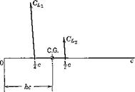
incompressible flow. The motion of the airfoil is a plunging oscillation; i. e. it is like that shown in Fig. 7.11», except that the flight path is a sine wave. The instantaneous lift on the airfoil is given in two parts (see Fig. 7.20):

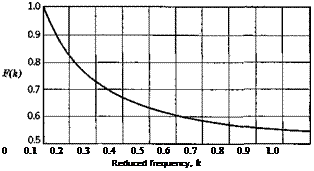
and F(Jc) and G(k) are the real and imaginary parts of the Theodorsen function C(k), plotted in Fig. 7.21. The lift that acts at the midchord is proportional to a = z/F, where z is the translation (vertically downward) of the airfoil. That is, it represents a force opposing the downward acceleration of the airfoil. This force is exactly that which is required to impart an acceleration z to a mass of air contained in a cylinder, the diameter of which equals the chord c. This is known as the “apparent additional mass.” It is as though the mass of the airfoil were increased by this amount. Except in cases of very low relative density /л = 2mjpSc, this added mass is small compared to that of the airplane itself, and hence the force CLi is relatively unimportant. Physically, the origin of this force is in the reaction of the air which is associated with its downward acceleration. The other component, , which acts at the } chord point, is associated with the circulation around the airfoil, and is a consequence of the imposition of the Kutta-Joukowski condition at the trailing edge. It is seen that it contains one term proportional to « and another proportional to a. From Fig. 7.19, the pitching-moment coefficient about the C. G. is obtained as
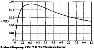
Подпись: Reduced frequency, k Pie. 7.21 The Theodorsen function.

From (7.10,6 and 7), the following derivatives are found for frequency 1c.

= 2 rrF(k)

Подпись: mCL = 77 + 2t7

Подпись:

Подпись: 0 0.1 0.2 0.3 0.4 0.5 0.6 0.7 0.8 0.9 1.0 Reduced frequency, k

Gma = 2nF(k)(h – i)

Gmsc = 77(h – x) + 2,7^ (h – i)

The awkward situation is evident, from (7.10,8), that the derivatives are frequency-dependent. That is, in free oscillations one does not know the value of the derivative until the solution to the motion (i. e. the frequency) is known. In cases of forced oscillations at a given frequency, this difficulty is not present.

When dealing with the rigid-body motions of flight vehicles, the character­istic nondimensional frequencies к are usually small, к < < 1. Hence it is

reasonable to use the F(k) and G(k) corresponding to к —»- 0. For the two­dimensional incompressible case described above, lim F(k) = 1, so that

CL = 2tt and Gma — 2n(h — J), the theoretical steady-flow values. This conclusion, that CL^ and Cm^ are the quasistatic values, also holds for finite wings at all Mach numbers. The results for CL and Gm& are not so clear, however, since lim G(k)jk given above is infinite. This singularity is marked for the example of two-dimensional flow given above, but is not evident for finite wings at moderate aspect ratio. Miles (refs. 7.13, 7.14) indicates that the к log к term responsible for the singularity is not significant for aspect ratios less than 10, and the numerical calculations of Rodden and Giesing (ref. 7.15) show no difficulty at values of к as low as.001. Filotas’ (ref. 7.16) more recent solutions for finite wings bear out Miles’ contention. Thus for finite wings definite values of and Cm^ can be associated with small but nonvanishing values of k. If the airfoil has a control flap, the hinge moment associated with a, , behaves like CL& and Gm . The limiting values described above can be obtained from a first-order-in-frequency analysis of an oscillating wing. To summarize, the a. derivatives of a wing alone may be computed from the indicial responses of lift, pitching moment, and hinge moment, or from first-order-in-frequency analysis of harmonically plunging wings.

PITCH DAMPING OF PROPULSIVE JETS

When gases flow at high velocity inside jet or rocket engines, there is a consequent rate of change of moment of inertia which leads to an inertia term in the moment equation [<#выв in (5.6,7)]. Instead of retaining it as a term on the r. h.s., it is convenient to transpose it to the l. h.s. and treat it as an external moment AGB = —JGB*s>Pi. Considering only pitching motion,

"O’

g.

the corresponding terms in the scalar moment equations (5.6,8) are

A£ = Іхуі

Ш = – lyq (7.9,16)

= lyzq

The corresponding q derivatives are therefore

A Lq = txy

ЬМв = -4 (7.9,17)

A^ « = 1„

PITCH DAMPING OF PROPULSIVE JETS
We restrict ourselves to consideration only of propulsion systems that have inertial symmetry with respect to the xz plane, so Ixy = Ivz = 0, and only ДЖв remains. Figure 7.16 shows three types of propulsion system, for each

of which we assume that the velocities are uniform across surfaces 1 and 2. For the jet engine 1 is the air inlet and for the rockets it is the moving boundary of the fuel. u2 is the jet exit velocity, щ is the inlet velocity for the jet, and the rate of movement of the relevant interface for the rockets.

The Oxz coordiate system of Fig. 7.16 is taken fixed to the solid part of the vehicle, and we focus our attention on the material system comprising the solid, liquid, and gaseous constituents of the vehicle at time zero. The boundaries of this system move in a time dt as illustrated; as a result its mass center moves away from the origin 0, and its moment of inertia changes. Let Iy be the moment of inertia around 0, and I’v be that around the displaced mass center, at coordinates (x, z). By the parallel axis theorem for moment of inertia we have

I’v = Iy — m(x2 + z2)

where m is, of course, the total vehicle mass. It follows that

ly = ly — 2m(x — + z

dt dt)

and at t = 0, when x — z = 0, І’у — ly. Thus the movement of the mass center associated with the jet flow does not contribute to the jet damping effect explicitly. The change in Iy in time dt is given by

dly — dt Г p%u2{x2 + z22) dA2 — dt f piU^x^2 + %i) (7.9,18)

JAz Ja і

In the second term, for a jet engine, px is, of course, the density of the inlet air. For a rocket it is, strictly speaking, the difference in density between the fuel and the adjacent gas. For all practical purposes the latter can clearly be neglected. If x2 and z2 are the component mean-square distances to the surfaces Ax and A2, (7.9,18) can be expressed as

iy = p2u2A2(x22 + z22) — pju^ixj2 + zx2) (7.9,19)

Now р(и{А( is the mass flux across A, h and may be taken constant for all three types of system (the fuel mass flow in jet engines is much smaller than the air mass flow). Thus

ly = m'[(x22 — Xj2) + (z2 — Zj2)] (7.9,20)

where m’ = А^щ is the mass flow rate out of the jet. In many practical cases, for elongated slender vehicles, the z2 terms may be negligibly small. The result for the pitch damping in that case is

It will be negative, corresponding to positive damping, whenever the C. G. is closer to the inlet or the fuel surface than to the nozzle exit. For compactness we may write f2 for (x22 — aq2) + (z22 — z,2) so that

Д Ma = – m’k2 (7.9,22)

PITCH DAMPING OF PROPULSIVE JETS Подпись: 4^.1! pVSc2 Подпись: (7.9,23)

The nondimensional coefficient follows as

It varies inversely as speed for constant propulsive mass flow m!. The thrust of the engine is given by

T — m’Vj

where Vj is the final velocity of the jet relative to the vehicle, so that (7.9,23) can be rewritten in terms of T instead of m!. The result is

ДCmq=-2CT?-^ (7.9,24)

V j c

For jet airplanes in cruising flight this contribution to Cm is usually negligible. Only at high values of CT, and when the Gm of the rest of the air­plane is small, would it be significant. On the other hand, a rocket booster at lift-off, when the speed is low, has practically zero external aerodynamic damping and the jet damping becomes very important.

CONTRIBUTIONS OF A WING

As previously remarked, on airplanes with tails the wing contributions to the q derivatives are frequently negligible. However, if the wing is highly swept or of low aspect ratio, it may have significant values of CL<i and Cm<i; and of course, on tailless airplanes, the wing supplies the major contribution. The q derivatives of wings alone are therefore of great engineering importance.

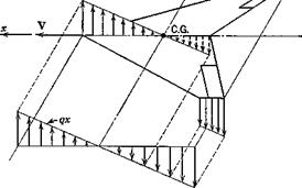
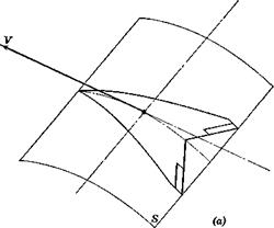
Unfortunately, no simple formulas can be given, because of the complicated dependence on the wing planform and the Mach number. However, the follow­ing discussion of the physical aspects of the flow indicates how linearized wing theory can be applied to the problem. Consider a plane lifting surface, at zero a, with forward speed V and angular velocity q about a spanwise axis (Fig. 7.13). Each point in the wing has a velocity component, relative to the resting atmosphere, of qx normal to the surface. This velocity dis­tribution is shown in the figure for the central and tip chords. Now there is an equivalent cambered wing which would have the identical distribution of velocities normal to its surface when in rectilinear translation at speed F. This is illustrated in Fig. 7.14a. The cross section of the curved surface S is

CONTRIBUTIONS OF A WING

CONTRIBUTIONS OF A WING

Fig. 7.13 Wing velocity distribution due to pitching.


(b)


Fig. 7.14 The equivalent cambered wing.


CONTRIBUTIONS OF A WING

shown in (6). The normal velocity distribution will he the same as in Fig. 7.13

^ T- dz dz q

Подпись: Hence Подпись: 1 Я 2 Z = - — X 2 V Подпись: (7.9,4)

V — = qx or — = — x дх дх V

and the cross section of S is a parabolic are. In linearized wing theory, both subsonic and supersonic, the boundary condition is the same for the original plane wing with rotation q and the equivalent curved wing in rectilinear flight. The problem of finding the q derivatives then is reduced to that of finding the pressure distribution over the equivalent cambered wing. Because of the form of (7.9,4), the pressures are proportional to qjV. From the pressure distribution, CLa, Gm, and Ghe^ can all be calculated. The derivatives can in principle also be found by experiment, by testing a model of the equivalent wing.

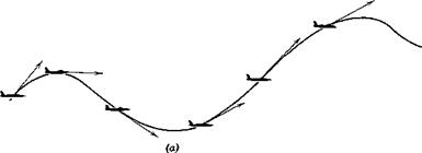
The values obtained by this approach are quasistatic; i. e. they are steady – state values corresponding to a = 0 and a small constant value of q. This implies that the flight path is a circle (as in Fig. 6.32), and hence that the vortex wake is not rectilinear. Now both the linearized theory and the wind – tunnel measurement apply to a straight wake, and to this extent are approximate. Since the values of the derivatives obtained are in the end applied to arbitrary flight paths, as in Fig. 7.116, there is little point in correcting them for the curvature of the wake.

CONTRIBUTIONS OF A WING

The error involved in the application of the quasistatic derivatives to unsteady flight is not so great as might be expected. It has been shown that, when the flight path is a sine wave, the quasistatic derivatives apply so long as the reduced frequency is small, i. e.

CONTRIBUTIONS OF A WING

where со is the circular frequency of the pitching oscillation. If l is the wavelength of the flight path, then

so that the condition к < 1 implies that the wavelength must he long compared to the chord, e. g. I > 60c for к < .05.

DEPENDENCE ON h

Because the axis of rotation, Fig. 7.13, passes through the C. G., the results obtained are dependent on h. The nature of this variation is found as

CONTRIBUTIONS OF A WING

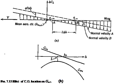
follows. Let the axis of rotation be at A, Fig. 7.15, and let the associated lift and moment be

Ola = OlJ; CmA = CmJ (7.9,5)

Now let the axis of rotation be moved to B, with the change in normal velocity distribution shown on the figure. Since the two normal velocity distributions differ by a constant, (the upward translation qc Ah) the difference between the two pressure distributions is that, associated with a flat plate at angle of attack

oc = -^AA (7.9,6)

V

This angle of attack introduces a lift increment acting at the wing aero­dynamic center of amount

ACl = Gl a = —— AhCL (7.9,7)

" « V x

so that for axis of rotation B,

@lb — ~~ ^La ^4

AGLi_ = -20La Ah

i. e. Gt is linear in h. The incremental moment about В is

■L-‘q

MJm = GLJAh + ACL(hB-hnJ

= [GLqa Ah – 2GLa Ah(hB – hnJ]q

CONTRIBUTIONS OF A WING
and = [°l, a – 2GBJhB – hnJ] Ah (7.9,9)

The forms of Gl^ and Gm are sketched on Fig. 7.156. h0 is the C. G. position for zero CL, h that for maximum Gm, and Cm is the maximum (least negative) value of Gm<. From (7.9,106) and (7.9,11a), we find

h = i(60 + hnJ (7.9,12)

The linear theory of two-dimensional thin wings gives for supersonic flow:

Подпись: and for subsonic flow CONTRIBUTIONS OF A WING CONTRIBUTIONS OF A WING

К = і

CONTRIBUTIONS OF A TAIL

As illustrated in Fig. 7.12, the main effect of q on the tail is to increase its angle of attack by (qlJV) radians. It is this change in at that accounts for

the changed forces on the tail. The assumption is implicit in the following derivations that the instantaneous forces on the tail correspond to its instantaneous angle of attack; i. e. no account is taken of the fact that it takes a finite time for the tail lift to build up to its steady-state value following a sudden change in q. [A method of including this refinement has been given by Tobak (ref. 7.12).] The derivatives obtained are therefore quasistatic.

THE q DERIVATIVES (Cw Cm,, Che)

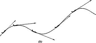
These derivatives represent the aerodynamic effects that accompany rotation of the airplane about a spanwise axis through the C. G. while a remains zero. An example of this kind of motion was treated in Sec. 6.10 (i. e. the steady pull-up). Figure 7.116 shows the general case in which the flight path is arbitrary. This should be contrasted with the situation illustrated in Fig. 7.11«, where q = 0 while a is changing.

THE q DERIVATIVES (Cw Cm,, Che)

THE q DERIVATIVES (Cw Cm,, Che)

Fie. 7.11 (a) Motion with zero q, but varying a. (6) Motion with zero a, bat varying q.

Both the wing and the tail are affected by the rotation, although, when the airplane has a tail, the wing contribution to CL and Cm^ is often negligible in comparison with that of the tail. In such cases it is common practice to increase the tail effect by an arbitrary amount, of the order of 10%, to allow for the wing and body.

THE DERIVATIVES Cw Cmy, Chey

The derivations for these three derivatives are exactly the same as for CDy above, and the results are exactly the same as (7.8,7) except that CD is replaced by the appropriate coefficient.

The Mach number effect on these three derivatives can he calculated from aerodynamic theory for both subsonic and supersonic flow. It is quite sensitive to the shape of the wing, high-aspect ratio straight wings being most affected by M, and highly-swept and delta wings being least affected. An upper limit is obtained by considering two-dimensional flow. For subsonic edges, the Prandtl-Glauert theory! and simple sweep theory combine to give for an infinite wing of sweepback angle Л

Подпись: M cos Л < IПодпись: 0L =a, a

THE DERIVATIVES Cw Cmy, Chey Подпись: (7.8,8)

(1 – M2 cos2 A) a where a( is the lift-curve slope in incompressible flow. Whence

THE DERIVATIVES Cw Cmy, Chey Подпись: M cos Л > 1

In level flight, with L = W, M2GL is a constant, so that M dCLjdM varies as 1/(1 — M2 cos2 Л). The theory of course breaks down at M ~ sec Л where an infinite value would be predicted, but nevertheless large values of M dGj-Jd M may be expected near that Mach number. At supersonic speeds, two-dimensional theory for swept wings gives the result

After differentiating with respect to M, the result obtained is again (7.8,8), which therefore applies for infinite yawed wings at both subsonic and supersonic speeds. The results given above derive from a linear theory that predicts proportional changes in the pressure distribution when M is changed—i. e. the pressure distributions remain unaltered in form, but changed in magnitude. Hence the results for Cm and would be of the same form, i. e.

Подпись: = 0Подпись: (7.8,9) (7.8,10) M9Cm M2 cos2 A

ЭМ 1-М2 cos2 A m‘

Подпись: andM3Cft M2 cos2 A

3M 1-М2 cos2 Л ы> f A. M. Kuethe and J. D. Schetzer, Foundations of Aerodynamics, Secs. 11.6, 11.14.

The vanishing of dCrJd M will hold only for truly subsonic and truly super­sonic flows. In the transition region between them there is a very important redistribution of pressure, such that the center of pressure on two-dimensional wings moves from,25c in subsonic flow to,50c in supersonic flow. This would lead to a negative дСт/дМ, possibly of large magnitude, in the transonic range. The vagaries of transonic flow are such that test results are the only way to get reasonably reliable results in this speed range.

THE DERIVATIVES Cw Cmy, Chey Подпись: ■* + **) Подпись: (7.8,11)

No general rules can be given for the derivatives with respect to pA or GT. Aeroelastic analysis or wind-tunnel testing must be used to find these. By way of example, we can calculate the contribution to dCmldpa associated with the fuselage bending treated in Sec. 7.4. We found there that the lift coefficient of the tail is given by

The pitching moment contributed by the tail is (6.3,8)

cmt = – vHcLt

Hence (^t = —V„ (7.8,12)

Wtaii H dp„

THE DERIVATIVES Cw Cmy, Chey Подпись: (7.8,13)

When (7.8,11) is differentiated with respect to pd and simplified, and the resulting expression is substituted into (7.8,12), we obtain the result

THE DERIVATIVES Cw Cmy, Chey Подпись: (7.8,14)

The corresponding contribution to Cm is

All the factors in this expression are positive, except for Cm, which may be of either sign. The contribution of the tail to Cmy may therefore be either positive or negative. The tail pitching moment is usually positive at high speeds and negative at low speeds. Therefore its contribution to 0OTfr is usually negative at high speeds and positive at low speeds. Since the dynamic pressure occurs as a multiplying factor in (7.8,14), then the aerolastic effect on Gmy goes up with speed and down with altitude.

Figure 7.6 shows the large effects of thrust coefficient on CL, cD, cm and values of the associated derivatives dCLldCT etc. can be found from data in this form.

7.8 THE V DERIVATIVES (CTv, CDy, CLp, Cmr, Chep)

This group of derivatives gives the changes that occur in the coefficient when the flight speed V changes, while the other variables, i. e. a, q, zE, de, remain constant. It is important to remember that the propulsion controls (e. g. the throttle) are also kept fixed.

THE DERIVATIVE CTy

7.8 THE V DERIVATIVES (CTv, CDy, CLp, Cmr, Chep) Подпись: _ у dC'y -ved T . e dv Є dv іPV2S

The derivative 0Ty depends on the type of propulsion system, specifically on how T varies with V at fixed throttle. In general it is given by

(дТ/дУ)е 2 Te

iPVe8 і PV*8

Подпись:^Ш-2СТ

PVeS

For constant-thrust propulsion, as for jet and rocket engines, dTjdV — 0

and j —■ —2G rp

For constant-power propulsion, TV = const, whence

TdV+ VdT = 0

Подпись: so that and Note that, from (7.3,2) ldJL = _ L.

w)e re

CTr=-ZCTe (7.8,2)

__ /Gn + Gl tan y

‘ 1 — aT tan у Je

For piston-engine-propeller systems, the usual fixed-control case implies fixed throttle and constant RPM. In that case the brake horsepower is constant, and the thrust is given by

Подпись: (7.8,3)TV = VPB

have

TdV + VdT = PB dr]

or

/3 T T PB/dr, dv)e ve ve dvh

(7.8,4)

and

GT — 3CT + Pp i3*1) F dvje

where rj = propulsive efficiency and PB is the engine shaft power. We then

After substituting for PB from (7.8,3) we get

Подпись: (7.8,5)
Подпись: 'Tv

This relation is useful, since the variation of t] with V would normally he known for a propeller-driven airplane.

THE DERIVATIVE CDy

In order to include all the main effects of speed changes formally, we shall assume that the drag coefficient is a function of Mach number M, the dynamic pressure

Pd = iPV2 (7.8,6)

and the thrust coefficient, i. e.

7.8 THE V DERIVATIVES (CTv, CDy, CLp, Cmr, Chep) 7.8 THE V DERIVATIVES (CTv, CDy, CLp, Cmr, Chep)

Gj) = GB( Pa> @t)

Since M = V/a, where a is the speed of sound, then

Подпись: = CЭМ 1 3pa 3 CT

^F = _; ы=р7 and

Подпись: Thus 7.8 THE V DERIVATIVES (CTv, CDy, CLp, Cmr, Chep) Подпись: Гр дсп Подпись: (7.8,7)

oV a oV oV

The aeroelastic effect on CDy (the pa term) is not likely to be large enough to need to be included in other than exceptional cases.