Category Dynamics of. Atmospheric Flight

THE FORWARD LIMIT

As the C. G. moves forward, the stability of the airplane increases, and larger control movements and forces are required to maneuver or change the trim. The forward C. G. limit is therefore based on control considerations and may be determined by any one of the following requirements:

(i) The stick force per g shall not exceed a specified value.

(ii) The stick-force gradient at trim, dPfdV, shall not exceed a specified value.

(iii) The stick force required to land, from trim at the approach speed, shall not exceed a specified value.

(iv) The elevator angle required to land shall not exceed maximum up elevator.

(v) The elevator angle required to raise the nose-wheel off the ground at take-off speed shall not exceed the maximum up elevator.

7.4 LONGITUDINAL AERODYNAMIC DERIVATIVES

The small-disturbance equations of motion given in Chapter 5 used the technique of expressing aerodynamic forces and moments in terms of the aerodynamic derivatives. The remainder of this chapter is devoted to a discussion of these derivatives. Some of the main aerodynamic derivatives have already been discussed in some detail in Chapter 6, i. e. CL , Gm^, Ghe^, CLs, Gmg, and GheS – Of the remaining a derivatives, CD is immediately obtained from (6.1,2) as

Подпись: (7.7,1)
Подпись: Gn=2KGfGr

where GLf is the value of CL in the reference equilibrium flight condition.

The thrust derivative GT^ is not readily predicted by theory, and would usually be small enough to neglect.

C. G. LIMITS

One of the dominant parameters of longitudinal stability and control has been shown in Chapter 6 to be the fore-and-aft location of the C. G. The question now arises as to what range of C. G. position is consistent with satisfactory flying qualities. This is a critical design problem, and one of the most important aims of stability and control analysis is to provide the answer to it. Since aircraft always carry some disposable load (e. g. fuel, armaments), and since they are not always loaded identically to begin with (variations in passenger and cargo load), it is always necessary to cater for a variation in the C. G. position. The range to be provided for is kept to a minimum by proper location of the items of variable load, but still it often becomes a difficult matter to keep the flying qualities acceptable over the whole C. G. range. Sometimes the problem is not solved, and the airplane is subjected to restrictions on the fore-and-aft distribution of its variable load when operating at part load.

THE AFT LIMIT

The most rearward allowable location of the C. G. is determined by con­siderations of longitudinal stability and control sensitivity. The behavior of

C. G. LIMITS

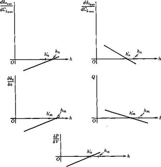
Fig. 7.10 The five control gradients.

the five principal gradients discussed in Chapter 6 are summarized in Fig.

7.10 for the case when the aerodynamic coefficients are independent of speed. From the handling qualities point of view, none of the gradients should he “reversed,” i. e. they should have the signs associated with low values of h. When the controls are reversible, this requires that h < h’n. If the controls are irreversible, and if the artificial feel system is suitably designed, then the control force gradient dP/dV can be kept negative to values of A > h’n, and the rear limit can be somewhat farther back than with reversible controls. The magnitudes of the gradients are also important. If they are allowed to fall to very small values the vehicle will be too sensitive to the controls. When the coefficients do not depend on speed, as assumed for Fig. 7.10, the N. P. also gives the stability boundary (this is proved in Chapter 9), the vehicle becoming unstable for h> h’n with free controls or h > hn with fixed controls. If the coefficients are not independent of speed, e. g. Gm = Cm( M), then the C. G. boundary for stability will be different and may be forward of the N. P. However (this is also shown in Chapter 9) the
nature of the instability is very much dependent on whether C is greater or less than zero, i. e. on whether the C. G. is forward or aft of the relevant N. P. In the former case the instability is less severe than in the latter, and hence the N. P. still provides a good practical criterion for stability.

By the use of automatic control systems (see Chapter 11) it is possible to increase the natural stability of a flight vehicle. Stability augmentation systems (SAS) are in widespread use on a variety of airplanes and rotorcraft. If such a system is added to the longitudinal controls of an airplane, it permits the use of more rearward C. G. positions than otherwise, but the risk of failure must be reckoned with, for then the airplane is reduced to its “natural” stabihty, and would still need to be manageable by a human pilot.

GROUND EFFECT

At landing and take-off airplanes fly for very brief (but none the less extremely important) time intervals close to the ground. The presence of the ground modifies the flow past the airplane significantly, so that large changes may take place in the trim and stability. For conventional airplanes, the take-off and landing cases provide some of the governing design criteria.

The presence of the ground imposes a boundary condition which inhibits the downward flow of air normally associated with the lifting action of the

wing and tail. The reduced downwash has three main effects, being in the usual order of importance:

(i) A reduction in e, the downwash angle at the tail.

(ii) An increase iti the wing-body lift slope amb.

(iii) An increase in the tail lift slope at.

The problem of calculating the stability and control near the ground then resolves itself into estimating these three effects. When appropriate values of де/dot, awb, and at have been found, their use in the equations of the foregoing sections will readily yield the required information. The most important items to be determined are the elevator angle and stick force required to maintain <?£max in level flight close to the ground. It will usually be found that the ratio ajawb is decreased by the presence of the ground. Equation (6.3,36) shows that this would tend to move the neutral point forward. However, the reduction in de/dot is usually so great that the net effect is a large rearward shift of the neutral point. Since the value of Cm& is only slightly affected, it turns out that the elevator angle required to trim at Cimax is much larger than in flight remote from the ground. It commonly happens that this is a critical design condition on the elevator, and may govern the ratio SJSt, or the forward C. G. limit (see Sec. 7.6).

EFFECT OF STRUCTURAL FLEXIBILITY

Many vehicles when flying near their maximum speed are subject to important aeroelastic phenomena. Broadly speaking, we may define these as the feedback effects upon the aerodynamic forces of changes in the shape of the airframe caused by the aerodynamic forces. No real structure is ideally rigid, and aircraft are no exception. Indeed the structures of flight vehicles are very flexible when compared with bridges, buildings, and earthbound machines. This flexibility is an inevitable characteristic of structures designed to be as light as possible. The aeroelastic phenomena which result may be subdivided under the headings static and dynamic. The static eases are those in which we have steady-state distortions associated with steady loads. Examples are aileron reversal, wing divergence, and the reduction of longitudinal stability. Dynamic cases include buffeting and flutter. In these the time dependence is an essential element. From the practical design point of view, the elastic behavior of the airplane affects all three of its basic characteristics: namely performance, stability, and structural integrity. This subject occupies a well-established position as a separate branch of aeronautical engineering. For further information the reader is referred to one of the books devoted to it (refs. 5.11 and 5.12).

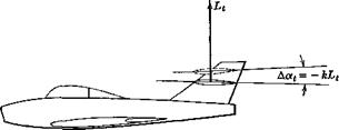
In this section we take up by way of example a relatively simple aero­elastic effect; namely, the influence of fuselage flexibility on longitudinal stiffness and control. Assume that the tail load Lt bends the fuselage so that the tail rotates through the angle Да, = —kLt (Fig. 7.9) while the wing angle of attack remains unaltered. The net angle of attack of the tail will then be

«■t = «■wb — e + h — kLt

EFFECT OF STRUCTURAL FLEXIBILITY

Fig. 7.9 Tail rotation due to fuselage bending.

and the tail lift coefficient at Se = 0 will be

CLt = = <*<(*«,6 -€ + »г – Щ)

But Lt = CLtyV>St, whence

Подпись: (7.4Д) (7.4,2) 0Lf = at(aab – e + it – kCLi§pV2St)

Solving for CLt, we get

1 + katStlpV*

Comparison of (7.4,2) with (6.3,26) shows that the tail effectiveness has been reduced by the factor 1/[1 + kat(p/2)F2(S’J. The main variable in this expression is V, and it is seen that the reduction is greatest at high speeds. From (6.3,36), we find that the reduction in tail effectiveness causes the

neutral point to move

forward. The shift is given by

a dot)

(7.4,3)

where

Д a, = a,(———————–

4 41 + kat±pV% J

(7.4,4)

The elevator effectiveness is also reduced by the bending of the fuselage. For, if we consider the case when be is different from zero, then (7.4,1) becomes

CLt = аМ«,ь – e + it – hCL±pV*St) + «А

and (7.4,2) becomes

c = at(xWb ~ с + h) + aA

Ь 1 + katlpV%

Thus the same factor 1/(1 + katpV2St) which operates on the tail lift slope at also multiplies the elevator effectiveness ae.

. THE INFLUENCE OF JET ENGINES

The direct thrust moment of jet engines is treated as shown at the beginning of this section, the constant-thrust idealization given in (7.3,6)

often being adequate. In addition, however, there is a normal force on jet engines as well as on propellers.

. THE INFLUENCE OF JET ENGINES
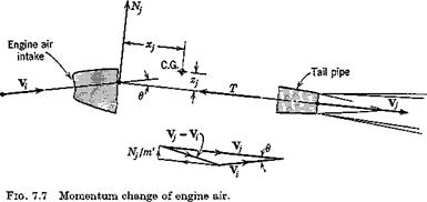
Jet Normal Force. The air which passes through a propulsive duct experiences, in general, changes in both the direction and magnitude of its velocity. The change in magnitude is the principal source of the thrust, and the direction change entails a force normal to the thrust line. The magnitude and line of action of this force can be found from momentum considerations. Let the mass flow through the duct he m’ slugs per second, and the velocity

vectors at the inlet and outlet be V* and Y3-. Application of the momentum principle then shows that the reaction on the airplane of the air flowing through the duct is

F = – V4) + F

Подпись: or, for small angles, Подпись: N} = ml Vі sin в Nj = m'Vfi Подпись: (7.3,11)

where F’ is the resultant of the pressure forces acting across the inlet and outlet areas. For the present purpose, F’ may be neglected, since it is approxi­mately in the direction of the thrust T. The component of F normal to the thrust line is then found as in Fig. 7.7. It acts through the intersection of Vf and Vf. The magnitude is given by

In order to use this relation, both V,; and в are required. It is assumed that Vt has that direction which the flow would take in the absence of the engine; i. e. в equals the angle of attack of the thrust line oq plus the upwash angle due to wing induction e}.

It is further assumed that the magnitude Vt is determined by the mass flow and inlet area; thus

у І = ~ (7.3,13)

АіРі

where A{ is the inlet area, and the density in the inlet. We then get for Nj the expression

jy, = -£!(«, + «,)

Apt

. THE INFLUENCE OF JET ENGINES . THE INFLUENCE OF JET ENGINES Подпись: (7.3,14)

The corresponding pitching-moment coefficient is

. THE INFLUENCE OF JET ENGINES Подпись: (7.3,15)

Since the pitching moment given by (7.3,14) varies with a at constant thrust, then there is a change in Gm given by

The quantities m’ and pt can be determined from the engine performance data, and for subsonic flow, 9е3/Эа is the same as the value dejda. used for propellers, dx^dot. can be calculated from the geometry.

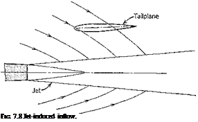
Подпись: FIG. 7.8 Jet-induced inflow.

Jet induced Inflow. A spreading jet entrains the air that surrounds it, as illustrated in Fig. 7.8, thereby inducing a flow toward the jet axis. If a tailplane is placed in the induced flow field, the angle of attack will be modified by this inflow. A theory of this phenomenon which allows for the curvature of the jet due to angle of attack has been formulated by Ribner

(ref. 7.2). This inflow at the tail may vary with к sufficiently to reduce the stability by a significant amount.

EFFECTS ON THE TAIL

The propeller slipstream can affect the tail principally in two ways. (1) Depending on how much if any of the tail lies in it, the effective values of at and ae will experience some increase. (2) The down wash values €0 and de/да may be appreciably altered in any case. Methods of estimating these effects are at best uncertain, and powered-model testing is needed to get results with engineering precision for most new configurations. However, some empirical methods (refs. 7.8 to 7.10) are available that are suitable for some cases.

EXAMPLE OF PROPELLER EFFECT

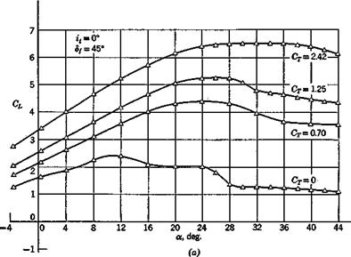
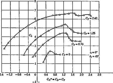
Figure 7.6 shows the large effects of thrust on a deflected-slipstream STOL configuration. The data presented are from wind-tunnel tests reported in

EFFECTS ON THE TAIL

EFFECTS ON THE TAIL

(b)

ref. 7.11. The configuration has two tractor propellers, full-span double slotted flaps deflected 45°, and a high tail. The drag coefficient Gjy plotted on Fig. 7.66 is the net streamwise force, and includes the thrust as a negative drag. The effect of the slipstreams on the downwash was large. For the case shown, 9e/9a increased by 100% between GT = 0 and 1.25. At the same time CL increased from.068 to.130. A large decrease in static margin at a = 0 due to adding thrust is found from the data:

Gm

.025

= 0 :

кп = –

ma _

—– =

= .37

GT

"a

.068

Cm

.0120

= 1.25:

Kn =

ma _

= .09

cL

.130

This represents a forward movement of the N. P. of 28% c.

THE INFLUENCE OF RUNNING PROPELLERS

The forces on a single propeller are illustrated in Fig. 7.5, where olp is the angle of attack of the local flow at the propeller. It is most convenient to resolve the resultant into the two components T along the axis, and NP in

the plane of the propeller. The moment asociated with T has already been treated above, and does not affect G„ . That due to N„ is

’ m p

Подпись:(7.3,7)

where CN = Npl^pV2Sv and Sp is the propeller disk area. To get the total

ДGm for several propellers, increments such as (7.3,7) must be calculated for

each and summed. Theory shows (ref. 7.4) that for small angles CN is

proportional to ap. Hence Np contributes to both Gm and dCmJda. The

latter is _

Подпись: da. Подпись: 8 Подпись: дар da

ЭС™ sp xp dCN dctP

If the propeller were situated far from the flow field of the wing, then dajda would be unity. However, for the common case of wing-mounted tractor propellers with the propeller plane close to the wing, there is a strong upwash e„ at the propeller. Thus

Подпись: and Подпись: да. да Подпись: (Ь) Подпись: (7.3,9)

aP = a + eP + const (a)

where the constant in (7.3,9a) is the angle of attack of the propeller axis relative to the airplane zero-lift line. Finally,

Подпись:dCmp = XpL depdCNv da S с да/ dap

INCREASE OF WING LIFT

When a propeller is located ahead of a wing, the high-velocity slipstream causes a distortion of the lift distribution, and an increase in the total lift. This is a principal mechanism in obtaining high lift on so-called deflected slipstream STOL airplanes. For accurate results that allow for the details of wing and flap geometry powered-model testing is needed. However, for some cases there are available theoretical results (refs. 7.5 to 7.7) suitable for estimates. Both theory and experiment show that the lift increment tends to be linear in a for constant GT, and hence has the effect of increasing awb, the lift-curve slope for the wing-body combination. From (6.3,36) this is seen to reduce the effect of the tail on the N. P. location, and can result in a decrease of pitch stiffness.

INFLUENCE OF THE PROPULSIVE SYSTEM ON TRIM AND PITCH STIFFNESS

The influence of the propulsive system upon trim and stability may be both important and complex. The range of conditions to be considered in this connection is extremely wide. In the first place, there are several types of propulsive units in common use—reciprocating-engine-driven propellers, turbojets, propeller-jets, and rockets. In the second place, the operating condition may be anything from hovering to reentry. Finally, the variations in engine-plus-vehicle geometry are very great. The analyst may have to deal with such widely divergent cases as a high-aspect-ratio straight-winged airplane with six wing-mounted counterrotating propellers or a low-aspect – ratio delta with buried jet engines. Owing to its complexity, a definite and comprehensive treatment of propulsive system influences on stability is not possible. There does not exist sufficient theoretical or empirical information to enable reliable predictions to be made under all the above-mentioned conditions. However, certain of the major effects of propellers and propulsive jets are sufficiently well understood to make it worth while to discuss them, and this is done in the following.

In a purely formal sense, of course, it is only necessary to add the appropri­ate direct effects, Gm and dCmJd& in (6.3,34 and 35), together with the indirect effects on the various wing-body and tail coefficients in order to calculate all the results with power on.

When calculating the trim curves (i. e. elevator angle, tab angle, and control force to trim) the thrust must be that required to maintain equilib­rium at the condition of speed and angle of climb being investigated (see

INFLUENCE OF THE PROPULSIVE SYSTEM ON TRIM AND PITCH STIFFNESS Подпись: (a) (b) Подпись: (7.3,1)

Sec. 6.4). For example (see Fig. 6.1), for flight at speeds below about M = 3 (see Sec. 5.9) and assuming that a2. 1

Solving for CT, we get

CT = °D + °L tan 7 (7.3,2)

1 — ay tan у

Except for very steep climb angles, ay tan у 1, and we may write approximately,

CT = CD + CL tan у (7.3,3)

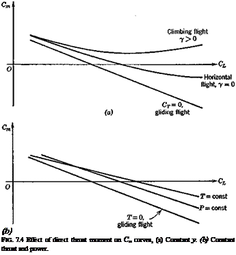
Подпись: (b) FIG. 7.4 Effect of direct thrust moment on Cm curves, (a) Constant y. (b) Constant thrust and power.

Let the thrust line be offset by a distance zP from the C. G. (as in Fig. 7.5) and neglecting for the moment all other thrust contributions to the pitching

INFLUENCE OF THE PROPULSIVE SYSTEM ON TRIM AND PITCH STIFFNESS
moment but Tzp, we have

If the power P is invariant, instead of the thrust, then T — P/V and we find


= * 1

1 _P_ fp ^nr3/2

•lip

W V

2 w c L

Мщ.

3 P

I–C*

dCL

~2W

J 2w 6 L


(e)


(7.3,6)


whence


(d)


Thus in the constant thrust case, the power-off Cm — CL graph simply has its slope changed by the addition of thrust, and in the constant power case the shape is changed as well. The form of these changes is illustrated in Fig. 7.46 and it is evident by comparison with 7.4a that the behavior of dCmjdCL is quite different in these two situations.

INFLUENCE OF HIGH-LIFT DEVICES ON TRIM AND PITCH STIFFNESS

Conventional airplanes utilize a wide range of aerodynamic devices for increasing These include various forms of trailing edge elements

(plain flaps, split flaps, slotted flaps, etc.), leading edge elements (drooped nose, slats, slots, etc.) and purely fluid mechanical solutions such as boundary layer control by blowing. Each of these has its own characteristic effects on the lift and pitching moment curves, and it is not feasible to go into them in depth here. The specific changes that result from the “configuration-type” devices, i. e. flaps, slots, etc., can always be incorporated by making the appropriate changes to Cm^ and CLm in (6.3,4) and following through the consequences. Consider for example the common case of part-span trailing edge flaps on a conventional tailed airplane. The main aerodynamic effects of such flaps are illustrated in Fig. 7.3.f

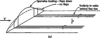
1. Their deflection distorts the shape of the span wise distribution of lift on the wing, increasing the vorticity behind the flap tips, as in (a).

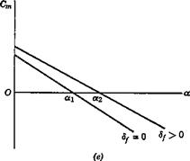
2. They have the same effect locally as an increase in the wing-section camber, i. e. a negative increment in Cm and a positive increment in От.

"tob

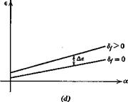
3. The down wash at the tail is increased; both e0 and де/дк will in general change.

The change in wing-body Gm is obtained from (6.3,4) as

AC’*,, = ACm^n + AGLJh – hnJ (7.2,1)

The change in airplane CL is

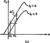
АСь = ДОіюь-й(|д6 (7.2,2)

and the change in tail pitching moment is

AGmt = atVH Де (7.2,3)

When the increments ДG„ . and Д GT are constant with a, then the only

ma. c….. J-‘vtb ’ V

f Note that a is still the angle of attack of the zero-lift line of the basic configuration, and that the lift with flap deflected is not zero at zero a.

INFLUENCE OF HIGH-LIFT DEVICES ON TRIM AND PITCH STIFFNESS

INFLUENCE OF HIGH-LIFT DEVICES ON TRIM AND PITCH STIFFNESS

Fig. 7.3 Effect of part-span flaps, (a) Change of lift distribution and vorticity. (b) Changes in forces and moments, (c) Change in CL. {d) Change in downwash. (e) Change in Cm.


INFLUENCE OF HIGH-LIFT DEVICES ON TRIM AND PITCH STIFFNESSINFLUENCE OF HIGH-LIFT DEVICES ON TRIM AND PITCH STIFFNESSINFLUENCE OF HIGH-LIFT DEVICES ON TRIM AND PITCH STIFFNESSINFLUENCE OF HIGH-LIFT DEVICES ON TRIM AND PITCH STIFFNESS

effect on CL and Gm is that of de/да., and from (6.3,31) and (6.3,34a) these are

A. a = ACLx=-at^ Ap (7.2,4)

о да

А<?та = (ft — KJ Aa + atVH A — (V.2,5)

The net result on the CL and Gm curves is obviously very much configuration dependent. If the Cm — a relation were as in Fig. 7.3e, then the trim change would be very large, from oq at df = 0 to ot2 after flap deflection. The CL at a2 is much larger than at ax and hence if the flap operation is to take place without change of trim speed, a down-elevator deflection would be needed to reduce atrim to a3 (Fig. 7.3c). This would result in a nose-down rotation of the aircraft.

EFFECT UPON CONTROL FORCE TO TRIM AND h’„

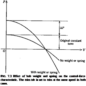
Подпись:
The added constant term in the control force will produce a change in the characteristic as shown in Fig. 7.2. The figure illustrates the case where the

trim tab is set to produce the same trim speed as when the ДР is absent. The parabolic part of the variation is different for the two cases (see 6.8,9) because of the altered trim-tab setting. It is clear from the figure that the net result of adding the ДР and moving the tab is to produce a steeper gradient at the given trim speed. Now the gradient has been shown in Sec.

6.9 to depend on the control-free static margin (h’n — h). Thus the increased gradient corresponds to an apparent backivard shift of the control-free neutral

point. The same conclusion is reached by consideration of the constant term of (6.8,9), which is proportional to (h’n — h). The apparent shift of the neutral point may be calculated directly from it, i. e.

EFFECT UPON CONTROL FORCE TO TRIM AND h&#39;„

or

Подпись: Дл: =А АР a’b2 GSecew

The term “apparent shift” of the N. P. is used above because the N. P. location depends on G’l and G’m^ and the latter are not influenced at all by ДP. This is readily demonstrated. When the pilot exerts no additional force on the control, the hinge moment is given by

A P c

Щ pV%ce ‘


(7.1,2)


+ Ghv. + b2de + bz8t


and hence the free elevator angle becomes

EFFECT UPON CONTROL FORCE TO TRIM AND h&#39;„

(7.1,3)


EFFECT UPON CONTROL FORCE TO TRIM AND h&#39;„

Equation (7.1,3) shows that the presence of ДP at constant speed simply changes (5<,Ггее by a constant. Consequently, substitution of (7.1,3) into (6.6,2) leads to the same values of C’L^ and G’m^ as given previously by (6.6,5). Hence from (6.6,11a) h’n is unchanged.

EFFECT UPON STICK FORCE PER g AND h’m

When AP is provided by a spring, then it is not dependent in any way on acceleration of the airplane. Hence the addition of a spring does not alter the stick force per д or the maneuver point. The bob weight, on the other hand, is affected by airplane acceleration. At load factor n, the effective weight of the bob is increased from W to nW, and hence induces an additional stick force of {n — 1) AP. The stick force per д is thereby increased by the amount

Подпись: AQ =(n-l)AP Ap

n — 1

Since Q is proportional to h’m — h, this increase moves the maneuver point aft. Consideration of (6.10,15) shows this shift to be

Ah’m = —————— ^———–

G8ecew a’b2(2fi – CLJ

This movement of the maneuver point however, unlike that of the N. P., is real, since the maneuver point is defined by the control force per g.