Category Fundamentals of Modern Unsteady Aerodynamics

Subsonic Flow about a Thin Wing

We are going to use the distributed acceleration potential rather than a single one to model the unknown lifting pressure distribution over the wing surface. For this

Подпись: W(x, y, z,t) = Подпись: ix tH—ЦМ (x— n) —- ab ( n) /R }dn dg, Подпись: (5.28)

modeling to work the lifting pressure must go to zero along the trailing edge in order to satisfy the Kutta condition. The lifting pressure as a discontinuity at point (П, g) of the surface is related to the acceleration potential at any point (x, y, z) at time t as follows

Подпись: Here, R(x — n)2 + b2 (y — g)2 + Z2

In Eq. 5.28 the amplitude of the lifting pressure enables us to express the simple harmonic representation in following form.

Подпись: (5.29)Dp(n; g; t) = DP(n, g)e“

We know the relation between the lifting pressure and the acceleration potential. Now, we have to relate the velocity potential to the lifting pressure so that we can impose the boundary conditions to obtain the lifting pressure for a prescribed motion of the wing. Equation 2.25 gives the relation between the two potentials. For a simple harmonic motion 2.25 becomes

W = ix/ + (5.30)

o x

Equation 5.30 is a first order differential equation for the velocity potential which has an explicit solution in the following form

x

p = 1 e—ixx/U j W(k, y, z)eixk/Udk (5.31)

Подпись: p(x; y; z) Subsonic Flow about a Thin Wing Подпись: -dk Подпись: (5.32)

Using 5.28 in 5.31 gives us the amplitude of the velocity potential in terms of the acceleration potential as follows

Prescribing the simple harmonic equation of motion for the thin wing as za = za(x, y)eix‘ the boundary condition at the surface reads as

Подпись: (5.33)w(x, y)= ix + U0x Pa (x, y)

Подпись: w (x, y) = lim z—>0 Подпись: op Oz Подпись: lim z— 0 Подпись: U S Подпись: /'(x, y, z, n, g)dn dg Подпись: (5.34)

Integrating the downwash expression over the whole surface S yields

Подпись: w (x, y) Subsonic Flow about a Thin Wing Подпись: Ар(П; g) lim Subsonic Flow about a Thin Wing

If we substitute 5.32 in to 5.34 we obtain the downwash in terms of lifting pressure as follows

(5.35)

The lifting pressure can be found by solving the integral equation, 5.35, once the boundary condition 5.33 is prescribed as the left hand side of Eq. 5.35. In order to simplify Eq. 5.35 let us define new parameters in terms of the old ones as follows.

x = x — n, y = y — g, x = m/U[f, r2 = b2(y 2 + z2)

Подпись: w (x, y) U Subsonic Flow about a Thin Wing Subsonic Flow about a Thin Wing Подпись: x Подпись: e image89

Using the new parameters we obtain

The singular inner integral part of 5.36 is subject to a limiting process, and it is called the Kernel function. If we denote the Kernel function with K(x’, y’) and the nondimensional pressure discontinuity with L(n, g) = Ар(П, g)/PoU2 the down – wash expression becomes

= JJL(n, g)K(x, y )dn dg (5.37)

S

Direct inversion of 5.37 is not possible therefore, numerical methods are used for that purpose.

Subsonic Flow

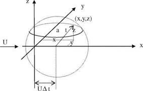
Подпись: Fig. 5.2 Spherical perturba-tion front at time t
image85

When the flow speed is less than the speed of sound which means the Mach number is under unity, the flow is called subsonic. In such a flow with a free stream speed U, a disturbance which was introduced at time s becomes the spherical front, as shown in Fig. 5.2, after the time duration of At at time t.

The disturbance reaches the point r from its origin with r = a At = a(t — s)

and in terms of the coordinates x, y, z and the times given above we have

2 2 2 2 2

Подпись: s Subsonic Flow Подпись: Mx ± Подпись: x2 + b2(y2 + z2) Подпись: (5.7)

a (t — s) = [x — U(t — s)] + y + z. If we solve for the time of introduction of the disturbance, s, we obtain

Подпись: s Subsonic Flow Подпись: Mx Подпись: x2 + b2(y2 + z2) Подпись: (5.8)

In 5.7 we have two different times for s. For the subsonic flow we have to choose the one which has the smaller value because s — t must be negative for subsonic flows. This is possible only for the following s.

Подпись: Ф(x, y, z,t) Подпись: q(s) 4njx2 + b2(y2 + z2) Подпись: (5.9)

Now, we can write the velocity potential for a source generated at time s and reached the point x, y, z at time t, using Eqs. 5.5-5.6.

If the intensity of the source varies simple harmonically in time, that is q(s) = qelms, then the potential with 5.8 reads as

– f+ak _Mx-px2+b2(y2+z2 ) ] I

/(x; y; z; t) =– (5.10)

4p x2 + b2(y2 + z2)

We can also obtain 5.10 using pure mathematical approach with a Lorentz type of transformation for which time coordinate is no longer absolute and given as follows

– = x, – = by, z = bz ve – = t + Mx/ab2, b = V1 — M2 (5.11)

For this transformation, the derivatives in old coordinates in terms of the new ones read as

0 0 0- 0 0- 0 0z 0 0- 0 M 0

0x 0- 0x + 0- 0x + 0z 0x + 0- 0x 0- + ab2 0-

and

Подпись: 0 0y b-, – = b-.

b 0-, 0z b0z

The second derivatives then become:

_0l – (0 M0]2 0L- r20L 0L – r20L

0x2 0- + ab2 0t, 0y2 0-2, 0z2 0z2

In Eq. 5.14, k2 is a positive number and the derivatives, denoted by ‘prime’, of h is taken with respect to transformed time coordinate. Since the right hand side of 5.14 is constant, it gives us two separate homogeneous, coupled only with constant k, equations for the functions g and h as follows.

Подпись: (5.15-a, b)

Subsonic Flow

h" + a2b4k2 h = 0

V2g + k2 g = 0

Eq. 5.15-a, is simple harmonic in time. Therefore, if we take ю = ab2k the general solution of 5.15-a becomes

h (X) = heixX (5.16)

Equation 5.15-b, on the other hand, is the well known Helmholtz equation which has a solution in transformed coordinates as (Korn and Korn 1968),

e±ikR

g(X X; z)=g R-, R = Vy2 + y2 + z2 (5.17)

Combining 5.16 and 5.17, the velocity potential in terms of / = g h becomes

/(X, X, Z, X) = / eix(X±R/ab2) /R (5.18)

Подпись:Подпись: (5.19)

Подпись: ію [H—1 M x- /(x, y, Z, t) = /e 1 ab2(
Подпись: /R, R = x2 + b2(y2 + z2)

where we have two solutions separated with ±. If we go back to the original (x, y, z, t) coordinates we will have

In Eq. 5.19, for the exponential term we take the one with—sign to have solution in agreement with 5.10.

In subsonic flows the acceleration potential rather than the velocity potential is preferred for its direct relation with the lifting pressure. Therefore, let us remember the relation between the two, the acceleration and the velocity potentials, as 2.25

Utilizing Eq. 2.25 with 2.21 the acceleration potential in terms the pressure and density of the farfield we obtain

W = P1—p (5.20)

As stated before, Eq. 5.20 gives the direct relation between the acceleration potential and the surface pressure which is to be used in determining the aero­dynamic coefficients. Recalling Eq. 2.26, reminds us that the acceleration potential also satisfies Eq. 2.24 whose solution for the acceleration potential is

W(x, y, z, t) = WeHt+^(Mx~R)]/R (5.21)

The acceleration potential can directly be related to the surface lifting pressure discontinuity in terms of doublet distribution. We can derive the expression for a potential written in terms of a doublet. Defining a doublet requires a pair of source and a sink which are of equal strength and distance of e apart from each other as shown in Fig. 5.3.

Now, let us express the potential for a source given by 5.21 in terms of a function f in the following manner, W = —Wf (x, y, z, t). For a sink with the same strength, the potential becomes W = Wf (x, y, z, t). The total effect of these two potentials placed on z axis with a distance e reads as

Подпись: (5.22)

image86
Подпись: W Подпись: (2.25)

W = W[f (x, y, z — e/2, t)—f (x, y, z + e/2, t)]

Подпись: W Подпись: lim e!0 W Подпись: We f (x, y, z + e/2, t)—f (x, y, z — e/2, t)' Подпись: (5.23)

If we multiply and divide 5.22 by e, and take the double limit of the resulting ratio for the strength going to infinity as e approaches zero we obtain

The limiting process employed on We results in
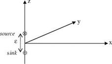
image87"Fig. 5.3 Source and sink pair placed on z axis

lim [—We] = A

jE—— 0

W—i

Подпись: W(x, y, z, t) Подпись: A0Zf (X; y; Z; t) Subsonic Flow Подпись: (5.24)

where A is a constant having a finite value. The limit on f is nothing but the derivative of f with respect to z, i. e.

Подпись: W(X; У; z,t) Подпись: Aeix[t+ab2(Mx—R)]/R2 — a Подпись: (5.25)
image88

If we take the derivative of the expression in curly parenthesis with respect to z we obtain

Now, we can comment on the physical meaning of acceleration potential given by 5.25 at the surface where z = 0. At this surface the value of potential is zero except for R = 0 where there is a singularity. Eq. 5.20 provided us the relation between the pressure and the acceleration potential. Rearranging 5.20 to obtain the pressure at a point (x, y, z) for a given time t gives us

P(X; У; z, t) =pi — PiW(X; y, z; t) (5.20)

We can express the lifting pressure in terms of the singular doublet strength A given by Eq. 5.24 as Ap = pi — pu / A. Dimensional analyses show that A must have the dimensions L4 T-2. Therefore, the strength of the doublet is related to the lifting pressure as follows

Подпись: (5.26)i2 Л

A = A p

P

Подпись: i2 0 W(X У, Z, t) =—AP 0P 0z Подпись: ix t+—(MX—R) Подпись: /R Подпись: (5.27)

Here, i is the characteristic length to be employed for defining the strength of the acceleration potential as the pressure discontinuity in following form.

We have finally obtained an expression, 5.27, for our mathematical model for lifting bodies in subsonic flows. Eq. 5.27, however, is developed for a doublet placed at the origin. In order to represent lifting surfaces, on the other hand, we need to derive the same expression for the effect of an arbitrary point on the surface.

Subsonic and Supersonic Flows

In a compressible medium like air, the propagation speed of small perturbations is equal to the speed of pressure waves which in turn is equal to the speed of sound (Shapiro 1953). As the velocity of the moving object gets close to the speed of sound in the air, the effect of compressibility can no longer be neglected. In other words, when the flow velocity is in the same order of magnitude with the prop­agation speed of the perturbations, we have to consider the compressibility effect. The low flow velocity, compared to propagation speed, enables us to neglect all compressibility effects and identify the flow as incompressible. The measure of compressibility in aerodynamics as a parameter is the Mach number which is defined as the ratio of the flow velocity to the local speed of sound. In this chapter we are going to study the compressible flow, ranging from simple to complex, based on the linear potential theory using point sources and sinks with intensities q related to the perturbation potential. Shown in Fig. 5.1, is the point source, with intensity q, having only radial velocity on the spherical surface whose radius is r.

With the aid of Fig. 5.1 and using the definition of the velocity potential, we can obtain the expressions for the velocity potential in terms of the intensity of the point source as follows.

(i) The relation between the velocity potential ф and the radial and tangential speeds for the steady incompressible flow:

10ф я 0ф • , q

Щ = and Ur = gives ф = —

r oh or 4nr

Subsonic and Supersonic Flows Подпись: (5.1)

since in Cartesian coordinates r2 = x2 + y2 + z2 then

U. Gulfat, Fundamentals of Modern Unsteady Aerodynamics, 129

DOI: 10.1007/978-3-642-14761-6_5, © Springer-Verlag Berlin Heidelberg 2010

Подпись: Fig. 5.1 Point source in three dimensions Подпись: A Subsonic and Supersonic Flows
Подпись: IN

"il

Subsonic and Supersonic Flows

(ii) The source expression for incompressible unsteady flow also satisfies the Laplace’s equation with time dependent source strength, q = q(t). The time dependent velocity potential then reads as

(ii) For the compressible unsteady flow we use the full form of 2.24 as follows

02/ і 0 T

Подпись:0x2 0y2 0z2 a2 0t 0x

and perform the coordinate transformation of Sect. 2.1.5 in moving coordinates we obtain the classical wave equation

02/ 02/ 02 / 1 02/

ox2+oy2 + oz2=a2 "о?2 (2:26)

The well known solution of the classical wave equation in moving coordinates is

We can go back to original coordinate system in Eq. 5.6 in terms of the free stream speed and the elapsed time t.

Now, let us use the physical models to express the mathematical derivations we have provided in this section.

Low Aspect Ratio Wing

Let us study the unsteady aerodynamic forces for the time dependent motions of low aspect ratio wings.

Low Aspect Ratio Wing Low Aspect Ratio Wing

For the thin and low aspect ratio wing as shown in Fig. 4.6 with its top and side views, we can make our simplifying assumptions as we did for the steady case to obtain the time dependent downwash expression in terms of the perturbation potential difference as follows

The lifting pressure coefficient for the unsteady flow was

Подпись:2 0 * 2 0 /.it

cp = —г —Дф H———– тгДф

Pa U2 0t Y U 0x Y

image77"Fig. 4.6 Low aspect ratio wing

y,

Here, Аф'(х, у, t)=

—b(x)

For the simple harmonic motion the downwash expression in terms of the surface equation

Wa(x, y) = iO)Za(x, y) + U^Za(x, y)-

The amplitude of the lifting pressure in terms of the perturbation potential reads as

2 2 0

cPa = U^ixA/0 + U ОХАф0 (4-64b)

Подпись: Аф '(x, y) Low Aspect Ratio Wing Подпись: (4-65)

If we allow elastic deformation and the camber only in chordwise direction, the downwash in Eq. 4.63 becomes independent of y; therefore, the integral becomes py. Accordingly, from 4.63 for the amplitude of the perturbation potential we obtain

Low Aspect Ratio Wing image78 image80,image81
image79

Lifting pressure coefficient from 4.64a, 4.64b reads as

(4-66)

In Eq. 4.66 if we take frequency as zero, we obtain Eq. 4.40 which was given for the steady case. The second term of the right hand side of 4.66 gives the phase difference between the lifting pressure coefficient and the wing motion.

Low Aspect Ratio Wing Подпись: (4-67)

Now, we can express 4.66 in more convenient form using the reduced fre­quency, k = xbo/U, and the nondimensional coordinates with superscript * written in term of root half chord, bo, as follows

The second term of the right hand side of Eq. 4.67 is the apparent mass term. In order to satisfy the Kutta condition this term needs to go to zero at the trailing edge. To remedy this and to be in accord with the experimental findings the lifting pressure coefficient is multiplied with an empirical factor (BAH 1996) given as

/ 21/2

F(x) = 1 – x* . (4.68)

Example 4: The wing given in Example 2 is undergoing a simple harmonic motion with h = heixt. Find the lifting pressure on the wing surface in terms of the wing geometry and the reduced frequency.

Solution: Using the fixed vertical amplitude and the wing geometry b(x) = (l/bO)x/2 in 4.67 we obtain

cPa = 4k2h* li1(x)-y2/bo — ikh*j->Vb (x)- y2/bo)

CPa = 4k2 hJ l*2 x*2 /4 — y2/b2 — ikh*—y/1*2 x*2 /4 — y2/b2.

Low Aspect Ratio Wing Подпись: k2h* l*2 x*2/4 — y2/bO — ikh* l*2 x*2/4 — y2/bO o dx* o

The empirical relation 4.68 is used as a multiplier to satisfy the Kutta condition

. Effect of Sweep Angle

The significance of sweep for a wing comes into the picture for compressible flows in achieving high critical Mach numbers. Here, for the sake of completeness we are going to briefly analyze the effect of sweep for incompressible flows.

Подпись: a(x*) = . Effect of Sweep Angle Подпись: e-ikn* dn* x* - n* Подпись: (4.61)

As we did for the steady flow, let us define the sweep angle K as the angle between the quarter chord line of the wing and the line normal to the free stream. It is, on the other hand, possible to find the aerodynamic coefficients via chordwise strip theory for the wings with the constant spanwise twist and downwash distri­bution. Multiplying Eq. 3.36a, b in Chap. 3 with cosK gives us the aerody­namic coefficients for the swept wings. For this case only, for the nonorthogonal coordinate system having its axis as the free stream direction and the half chord line, we can write downwash expression along the chord as follows

Inverting Eq. 4.61 and substituting it into the lifting pressure coefficient helps us to find the sectional lift coefficient with chordwise integral of the lifting pressure. At each section, assuming that the strip theory is valid, spanwise inte­gration of the sectional values of lift will give us the total lift (BAH 1996).

Another approach here is redefining the coordinate system as у in spanwise direction and x to the normal to spanwise direction. If we now denote the vertical
displacement by r and torsion by s, we can find the aerodynamic forces as functions of r and s (BAH 1996).

Both of the approaches are not quiet sufficient from the aerodynamical angle. Therefore, in practice a semi-numerical method called ‘doublet lattice’ is used extensively. We will be studying the doublet lattice method in next chapter.

Arbitrary Motion of a Thin Wing

For elliptically loaded thin wings it is possible to determine the indicial admittance functions like Wagner and Kussner functions for arbitrary motions of wing. Accordingly for the sudden angle of attack change from 0 to ao we have the Wagner function to give the lift creation

cL (s) = 2nao/(s) (4.59)

and, similarly for the effect of the gust with magnitude wo on the lift change as the Kussner function

Wr-,

cLg(s) = 2paa—v(s) (4.60)

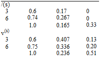
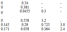
Here, s is the reduced time based on the root half chord. The Jones approach for the Wagner and Kussner functions are given in exponential form which has coefficients and exponents given in Table 4.1 and their plots are provided for a wing with an aspect ratio of 6 (Fig. 4.5).

Table 4.1 The Wagner and the Kussner functions variations with respect to aspect ratio

Подпись: /(s) 3 0.6 0.17 0 6 0.74 0.267 0 1.0 0.165 0.335 v(s) 3 0.6 0.407 0.136 6 0.75 0.336 0.204 1.0 0.236 0.513
Подпись: 0 0.54 - - 0 0.381 - - 0 0.0455 0.3 - 0 0.558 3.2 - 0.145 0.29 0.725 3.0 0.171 0.058 0.364 2.42

AR bo b1 b2 b3 b1 b2 b3

= bo – bie_bi°s – b2e~bs – Ьзє-Ьs

Numerical Solution

image74

The aerodynamic coefficients for the wings undergoing simple harmonic oscilla­tions, the integro-differential equation 4.51 can be solved to obtain the amplitude of the reduced circulation as we did for the steady case. For this purpose, expanding the reduced circulation into Fourier like series will give us the algebraic system of equations. Before expanding into the series, let us first transform the spanwise coordinates with y* = l* cos / ve g* = l* cos в. The series form of the reduced circulation in series can be expressed as follows

Here, a denotes rotation, h vertical displacement and b flap motion. With this notation Eq. 4.51 becomes the following set of equations

Подпись: [Sn] =

Si (kol*; /1 )S3 (k0l*, /1).. .S2N-1 (kol*; /1 ) S1(kJ*, /2ШКІ*, /2). . – S2N-1(kol*, /2)

S1(kol*, /N)S1(kol*, /N).. .S2N-1(kol*, /n)

The entries of the matrix Sn and the right hand side of Eq. 4.55 are complex. Therefore, coefficients Knj are obtained as N complex numbers. These coefficients help us to find the reduced circulation values at each station. From the reduced circulation values we obtain the amplitude of the circulation. Integrating the cir­culation along the span gives us the amplitude of the total lift. The total lift value being complex gives us the phase difference between the simple harmonic motion of the wing.

Подпись: U Numerical Solution

For a rectangular planform with a constant chord 2b the reduced frequency along the span remains the same. Therefore, for a given frequency and the mode shape the reduced circulation becomes proportional with the amplitude of the motion. Hence, the right hand side of 4.54 is simplified as follows.

While computing the coefficients Knj from 4.54 the right hand side of the equation may become real. If we denote the new coefficients with K’nh, we can write

K’nh = Jew h to have 4.54 as follows

Numerical Solution Numerical Solution

kHl12)(k)b

Numerical Solution Подпись: (4.58)

Similarly, knowing the coefficients K’nh, we can calculate the amplitude of circulation at spanwise stations from the reduced circulation values as follows.

Example 3: A rectangular wing with an aspect ratio 6 undergoes vertical oscil­lation with k = 2/3 and amplitude h. Find the spanwise distribution of lift.

Solution: Using the Reissner’s tables and the 2-D lift value: L(2)/2pU2h = -0.425 + 1.19г we find

/= 0.0; 0.4; 0.8; 1.0

L/2pU2h =-0.441 + . 195i; -0.455 + 1.18г, -0.461 + 1.071г, -0.042 + 0.23г

Reissner’s Approach

The following assumptions are going to be made to simplify the integrals.

i) Similar to the lifting line theory, we assume the wing is loaded as quasi two dimensional at any spanwise station y.

ii) The chordwise wake vortex is projected forward from the trailing edge to a spanwise line passing through the point where the downwash is to be calculated.

iii) The spanwise vortex of the wake which deviates from two dimensional behavior can be projected up to a line passing through the calculation point.

Let us see now, the simplifications of the terms of Eq. 4.47 with following assumptions.

The integral in K(q) is named the Cicala function with its argument being

q = x(y – g)-

Подпись: 2x — xt — xt 2b ’ Reissner’s Approach

Let

We can see the difference between the two dimensional lifting pressure coef­ficient 3.23 in Chap. 3. Here, r is also a function of C(k) and shows us the spanwise variation of the circulation.

The aerodynamic coefficients can be calculated using the Reissner’s theory by the following steps.

For simple harmonic motion; (i) if only bending is considered: h(y*, t) = heix‘/h(y*), (ii) if torsion about an axis is considered: a(y*, t) = aeixt/a(y*), are employed.

1) Since the reduced frequency and the wing geometry is known l(k) and XX(2)(y*) are determined to solve 4.51 to find XX(y*).

2) 2) XX(2) (y*) and XX(y*) are known, r is determined.

3) At any station y* the aerodynamic coefficients are found using 2-D theory.

4) These coefficients are corrected with known values of r as the 3-D solution, as follows

ALh(y*, t) = 2npU2b0[ikrh(y*)]h(y*, t)/ba ALa(y*, t) = 2npU2b0[ik(1/2 – a)aa(y*)ha(y*, t).

Подпись: •o

Summary of the Reissner’s Theory:

i) Compared to a 2-D case, non circulatory term does not change

ii) At the wing tips non circulatory terms can contribute

iii) As compared with the experimental values for rectangular wings good agreement is observed for the aspect ratio values down to 2.

During experiments it is difficult to reduce the viscous effects on oscillating wings. However, at high reduced frequencies these effects are expected to be low. In their numerous experimental and computational work, Reissner and Stevens have shown that the finite wing effects can be neglected depending on the reduced frequency and the aspect ratio values. In summary:

1) For the wings with an aspect ratio around 6 if the reduced frequency is higher than 1, and for the wings with an aspect ratio around 3 if the reduced frequency is higher than 2, 3-D effects can be neglected.

2) For the wings with an aspect ratio around 6 if the reduced frequency is less than 0.5, and for the wings with an aspect ratio 3 if the reduced frequency is lees than 1, 3-D effects can not be neglected.

Unsteady Flow

IIn this section we are going to study, for the sake of completeness of the unsteady aerodynamic theory, the incompressible flow past some special planform under­going time dependent motions. It has been shown that steady flow past a finite wing created zero spanwise vortex at the wake, yw = 0, and according to 4.7b chordwise vorticity at the wake was constant, i. e., = constant. For two

dimensional unsteady flow, the time variation of the effect of wake vorticity on the profile was reflected by Theodorsen function. Now, let us consider the effect of wake vorticity on the finite wing surface for simple harmonic motion. Let Ra

Подпись: Wa(x, y, t) = wa(x, y)elm‘ Unsteady Flow

denote the wing surface and Rw the wake region for a wing whose surface motion is given by za(x, y, t) = Za(x, y)elxt. The downwash at the surface reads as

With the aid of 4.4, the amplitude of downwash in terms of vortex sheet strength becomes

– , Ї W f-a(i. g)(x – n)+-a(i. g)(y – Ц)лйл

Подпись:”a(X, y)=-4-Jj [(Х-П)’^,^,^ d {dg

Ra

– _L Z Ui. g)(x – fl + Mi;,g)(y- ()d {d,

4pR [(x – i)2 + (y – g)2]J/2

Ra

Подпись: Гa(() ixxt _ix! - Cw(i, () = -ik0— e U e U with Гa(g) Unsteady Flow

As we did before, to obtain the relation between the bound circulation Ca and the vortex sheet strength – w, we will, similarly, at a spanwise station g write the following relations in three dimensional case

Подпись: 0

xl(()

Here, the trailing edge is given by xt = xt(g).

— (( .xxL

Подпись: W Unsteady Flow

Defining the reduced circulation as X(g) =-% ei и, the wake vortex sheet strength reads as – w(i, g) = —ik0X(g)e-i"U. The continuity of the vorticity, Odf = °(, once integrated with respect to n gives,

Подпись:xt (g)

= 0( -(i’ g)di’+0(

xi (g)

Подпись: _0_ 0g Подпись: bo X(g)e iU dg

Подпись: C -ik0X(g) J e-i_Udi xt(g)
Подпись: —W 0g b0X(g)e

After performing last two integrals we obtain

Substituting these into 4.46 gives

Подпись: wa (x, У)1 Ui, g)(x – 0 + Шg)(y2- g)dndg

Подпись: (4.47)ApJ [(x – i)2 + (y – g)2]3/2

Ra

1 ff – x-ik°X(g)(x – n) +bodi(g1(y – g)A..A 4* JJ e " [(x – i)2 + (y – g)2]3/2 ig

Rw

The first integral of Eq. 4.47, using continuity of vorticity, can be written in terms of ya to obtain the integral equation between the downwash and the unknown bound vortex strength. As we did for the case of steady flow, we make some assumptions to simplify the double integrals. Let us now consider the Reissner’s simplifying approach as given in (BAH 1996).

Low Aspect Ratio Wings

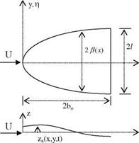
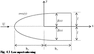
Prandtl’s theory works for high aspect ratio wings and Weissinger’s theory works for wings with medium aspect ratios. Jones’ theory, on the other hand, is applicable to the wings having low aspect ratio. By studying Jones’ theory, we will be covering all ranges of aspect ratios for the thin wings. In low aspect ratio wings we usually study the planforms having curved leading edges as shown in Fig. 4.3.

Low Aspect Ratio Wings

Since the trailing edge is a straight line, the integral Eq. 4.11b can be inverted. This time we neglect (y — g)2 compared to (x — f)2 to obtain

Подпись: Fig. 4.3 Low aspect ratio wing

Taking care of the terms with absolute value and breaking the integrals we obtain

Low Aspect Ratio Wings

If we write the bound vortex sheet strength in terms of the perturbation potential differences between the upper and lower surface, Аф’ = ф’и — ф’ we have

The integral in Eq. 4.33 is taken at a section from leading edge to a point x on the chord. In order to cover the full wing, the spanwise integration must be taken from ±1 to ± b(x) as shown in Fig. 4.3. Equation 4.32 becomes

b(x)

Подпись: (4.34)U! r=-h y—g щАф,(х-g)dg

—b(x)

Low Aspect Ratio Wings Подпись: (4.35)

Equation 4.34 can be directly inverted. Nondimensionalizing with y* = y/b(x) and g* = g/b(x) Eq. 4.34 then reads as

If we further nondimensionalize the following integral to obtain

11

Подпись: (4.36)OMdg.’ ^ ‘аф’ = 0.

0 g b(x) 0 g* b(x) ф

11

Using the property as f (g*) = ДгАф’ having zero integral between —1 and 1 as

follows we have

Подпись: 2“ y 1

Подпись: f (y*) = Low Aspect Ratio Wings Low Aspect Ratio Wings Подпись: (4.37b)

g(y*) = 2“ У ~T~:*dn* and if У f (n*)dn* = 0 then (4.37a)

Taking care of the signs and using – UOr1 for g in 4.37a, 4.37b we have

1

OA/’ = 2U f bzaJ 1 – n*2d *

Oy 1 – y*2 Ox y* – n* П

Подпись: OA/' 0y Low Aspect Ratio Wings Подпись: (4.38)
image68

In dimensional form it becomes

Подпись: cp Подпись: 2ca_ U Low Aspect Ratio Wings Подпись: y 2 _O OA/ixzV UOx Oy У -b(x) Подпись: (4.39)

The linearized form of Kelvin’s equation, 3.5 in Chap. 3, gives us the relation between the lifting pressure coefficient and the surface vortex sheet as follows

Since the integrand of 4.39 is equal to the right hand side of 4.38, for the known wing geometry the lifting pressure coefficient can be found via 4.39.

Low Aspect Ratio Wings Low Aspect Ratio Wings Low Aspect Ratio Wings Подпись: i±nl У-£d n- 1 - g * yy * - g *
image69

If we assume that for the low aspect ratio wings the elastic deformations and the camber exist only in the chordwise direction, i. e., OzJOy = 0, the integral in 4.39 is easily evaluated. The singular integral given below evaluates to

= “y.

Low Aspect Ratio Wings Подпись: nydy /b2(x)-y2
image70

If above integral is placed in 4.38 we obtain

(4.40)

Equation 4.40 provides the lifting pressure coefficient explicitly for the low aspect ratio wings. The validity of 4.40 depends on satisfying the Kutta condition at the trailing edge. The first term of 4.40 goes to zero for uncambered wings. The second term on the other hand is zero if the span remains constant at the trailing edge. Satisfying these two conditions makes the Jones’ approach applicable, otherwise it will not be applicable. Figure 4.3 has a planform shape which has a constant span at the trailing edge to satisfy the Kutta condition.

Let us find the sectional lift of a low aspect ratio wing by integrating 4.40 along the chord.

bo bo

Подпись: dxПодпись: (4.41)

image71,image72
Подпись: dza 4b (x)
Подпись: db

Г’М=2 PU cr. dx =-2„U’- OX [|y b2(x)-f-

Xl Xi

=-2pU2pr-y2( I-),

Подпись: L Подпись: i [ L'(y)dy l Подпись: ppU212 - = ppU2l2a Подпись: (4.42)

The end result of 4.41 tells us that a low aspect ratio wing deformable only in chordwise direction is elliptically loaded and this load is proportional with the angle of attack at the trailing edge. The total lift now can be found by integrating 4.41 in spanwise direction.

Подпись: dcL 2pl2 da S Подпись: pAR. 2 Подпись: (4.43)

Here, a is the angle of attack for a straight planform wing. If we write the aspect ratio as follows AR = (2i)2/S, the lift line slope for the wing becomes

Equation 4.43 is used for usually delta wings.

Low Aspect Ratio Wings Low Aspect Ratio Wings Подпись: (4.44)

Now, we can also calculate the chordwise variation of lift which is usually done for the delta wings.

Jones’ approach gives small downwash values compared to the free stream speed. For low aspect ratio delta wings this means small cross flow velocity even for the high free stream speeds in compressible flows. The cross flow becoming incompressible enables us to apply Eq. 4.43 even for the case of supersonic flows.

As seen from Eq. 4.41, the spanwise load distribution is elliptic which now yields an induced drag for the low aspect ratio wings

CDi = CL/(pAR). (4.45)

Example 2: For a low aspect ratio delta wing with angle of attack a, plot the chordwise load distribution on the wing.

Подпись: L'(x) = —npU2 dx Low Aspect Ratio Wings Подпись: l2 npU2a (x + bo)/2 b2

Solution: The equation of leading edge is given by b(x) = (x + bo)l/(2bo). Equation 4.44 gives the chordwise distribution as follows

and ci(x) = yU^bb = na|r(x + bo).

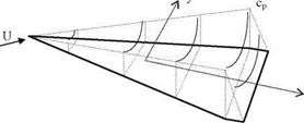
Подпись: Fig. 4.4 Spanwise load dis-tribution according to Jones’ theory Подпись: x
image73

In order to satisfy the Kutta condition the trailing edge ends with a constant span as shown in Fig. 4.4.