Category Fundamentals of Modern Unsteady Aerodynamics

Incompressible Flow About an Airfoil

The physical characteristics of external flow past a thin airfoil at a small angle of attack enables us to build a simple mathematical model of the flow. We assume here our profile starts to move impulsively from the rest and reaches the constant speed of U in zero time. If the viscous forces exist, their resistance to the impulsive motion will be so large that the required force to move the airfoil will also be incredibly large. However, if we neglect the viscous effects at the beginning, the assumption of impulsive start of a motion will be more meaningful. Under this assumption, we can model the external flow in connection with the creation of lift via the bound vortex formation around the airfoil in a free stream and explain the whole phenomenon by means of Kelvin’s theorem which was introduced in Chap. 2.

3.1 Impulsive Motion

When the airfoil starts its translational motion impulsively, as observed from the body fixed coordinates, the air suddenly starts rushing towards it with the speed U and creates a velocity field V = V(x, z) parallel to the surface of the airfoil as shown in Fig. 3.1. The fluid particles move along the streamlines of the flow field. The characteristic streamline of the flow is the stagnation streamline which comes at the front stagnation point and branches into two on the surface and leaves the surface of the airfoil at the rear stagnation point. The fluid particles which move on the stagnation streamlines have naturally zero velocities at the stagnation points. There are two stagnation points for this external flow.

The fluid particles on the frontal stagnation streamline first decelerate towards the frontal stagnation point and after passing the branch point they accelerate over the upper and lower surfaces until they reach their maximum velocity. The par­ticles moving on the upper surface move faster in a narrow passage because of the thickness of the airfoil and they slow down to zero velocity until they reach the

U. Gulfat, Fundamentals of Modern Unsteady Aerodynamics, 59

DOI: 10.1007/978-3-642-14761-6_3, © Springer-Verlag Berlin Heidelberg 2010

Incompressible Flow About an Airfoil

image38

rear stagnation. At the lower surface, however, the accelerating flow particles move towards the trailing edge and almost circle around it and reach the rear stagnation point which for the time being is at the upper surface. The flow picture looks very unsymmetrical and the location of the stagnation points are different from the leading and trailing edges.

The velocity vector which is parallel to the surface and nonzero except at the stagnation points will be used as the edge velocity of the boundary layer which is introduced by Prandtl for analyzing the viscous effects. In the boundary layer, however, the velocity values will go to zero at the surface because of the no slip condition as shown in Fig. 3.2.

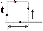
At the onset of impulsive motion very high velocity gradients take the shape shown in Fig. 3.2 in a short duration and the outside of the thin boundary layer a very large flow field remains potential. In the boundary layer the viscous effects are likely to generate a part of a circulation which contributes to the overall circulation used in generation of lift. Now, we can use our model in a boundary layer of thickness d with calculating the infinitesimal circulation dC over a rect­angular boundary whose length is ds as shown in Fig. 3.3. At the left face of the rectangle, the vertical velocity is v and with increment ds its value at the right face is v + dv, and V(x, y) is the edge velocity. The infinitesimal circulation in clockwise direction becomes

dr = 0. ds + v. d + V(x, z). ds – (v + dv). d. If we neglect the second order term dv. d we find: dC = V(x, z). ds. Accordingly, the rate of increase of circulation reads as

Подпись: dr ds

Подпись: Fig. 3.2 Velocity profile in a boundary layer Incompressible Flow About an Airfoil Подпись: V(x,z) ►
image39

V (x, z) = y.

Подпись:

Подпись: the wall image40 Подпись: A 5

Fig. 3.3 Local circulation dC

The boundary layer at the surface can be modeled as a vortex sheet with strength у while the outside of boundary layer is the potential flow region. This modeling represents the physics of the external flow. Let us use Kelvin’s theorem to find the total time variation of the circulation value in the flow field of the impulsively started airfoil According to Kelvin’s theorem, the total circulation remains constant throughout the motion. Since the motion starts from rest, the total circulation at the beginning is zero and remains zero to give

Г = y. ds = 0
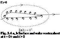
Подпись: Га=0 Fig. 3.4 a, b Surface and wake vortex sheet at t = 0+ and t > 0 image42

The closed integral here is evaluated around the airfoil on an arbitrary closed loop. For the sake of convenience, the closed loop can be chosen as the airfoil surface. As stated before, right after the start accelerating air particles at the bottom surface turn around the trailing edge with a very high velocity. The sharper the trailing edge, the more the speed of turning. Therefore, there is a limit to the turning speed after which the increase is not physically possible because of the pressure drop around the trailing edge. For the physically possible case, after the onset of motion the counter clockwise rotating vortex sheet of the bottom surface tries to turn around the sharp trailing edge but separates from the surface and gets carried downstream while the clockwise rotating vortex sheet of upper surface moves toward the trailing edge. The lifting force which was zero initially starts growing. In Fig. 3.4a, shown is the t = 0+ time depiction of the flow field with the upper and lower vortex sheets mentioned above. A short while after the start, the upper surface vortex sheet moves at the sharp trailing edge, and pushes

the lower surface vortex sheet down to wake until the rear stagnation point reaches the trailing edge. After this time, the flow becomes stable on the airfoil with the constant bound circulation Га as shown in Fig. 3.4b at time t > 0.

As seen in Fig. 3.4b, there are two different circulations in the flowfield. The first one is due to the bound circulation on the airfoil and the second one is due to the wake circulation. We calculate both of the circulations on clockwise paths as shown with dashed lines. The value of bound circulation can be simply found by adding the upper and lower vortex sheet strengths. The wake circulation, on the other hand, consists of only the counter clockwise rotating vortices which then add up to — Га. According to the Kelvin’s theorem, the total circulation must be zero which makes the bound circulation value Га. The picture on the upper surface remains the same, meaning that the bound circulation is present all the time moving with the airfoil to keep the rear stagnation point at the trailing edge.

At the wake, however, the counter clockwise vortices shed into the down­stream, get together and form the starting vortex of strength — Га and stay at the far wake. Although it retains the same strength for a long time, its effect on the airfoil is negligible according to the Biot-Savart law since it is far away from the airfoil.

As the velocity at the trailing edge becomes zero, the vortex sheet strength of upper and lower surfaces around the trailing edge becomes equal in magnitude and opposite in sign. That means as the steady state is reached, the shed vortices into the wake cancel each other to result in no vortex sheet in near wake. Having zero velocity at the sharp trailing edge is called Kutta condition. It is the Kutta con­dition which generates a positive circulation and in turn creates the lifting force on the airfoil. It has been observed experimentally that 90% of the lift on the airfoil is generated with 3 chord travel of the airfoil after the impulsive start, (Kuethe and Chow 1998). The early computational fluid dynamics studies with Navier-Stokes solutions had indicated that almost all the lift is generated within the 4 chord of travel of an airfoil after the impulsive start (Gulcat 1981).

Now, we can study the steady flow thin airfoil aerodynamics by considering vortex sheet present at the surface of the profile.

Initial and Boundary Conditions

The study of aerodynamical problems with real gas effects requires solution of a system of partial differential equations which are first order in time and second order in space coordinates. In order to solve Eq. 2.49 to determine the flow field, all dependent variables must be prescribed at time t = 0, and for all times t at the boundaries of the computational domain. All the prescribed values must be in accordance with the physics of the problem. As the initial conditions for the unknown values of U we prescribe the undisturbed flow conditions, i. e., u = 1, v = w=0 which represents the impulsive start of the flow. Under these conditions the initial values for the unknown vector in generalized coordinates become fp0

p0

Подпись: u(t = 0, n, g, 1)Подпись: (2.80)0

0

£°

c0J

Here, po is the initial value for the density, eo is the initial value for the energy and cf is the initial value of the ith specie.

As for the boundary conditions: (i) the unknowns at the surface, and (ii) farfield boundary conditions must be provided.

Accordingly:

i. As the no slip condition at the surface: U(t, i, g, 1 = 0) = 0 is prescribed. (In Fig. 2.6, 1 = 0 prescribes the surface). In reactive flows the catalicity of the surface determines the value of the concentration gradients,

ii. At the farfield: for 1 = imaks U(t, П, g, 1 = 1maks) = U 1 is prescribed, and the flux condition at П = imaks is Щ = (0),

iii. If there is a symmetry condition as shown in Fig. 2.6b, we prescribe the flux normal to the symmetry as Щ = (0).

Turbulence Modeling

At high free stream speeds external flows are likely to go through a transition from laminar to turbulence on the airfoil surface close to the leading edge. Depending on the value of the Reynolds number most of the flow on the airfoil becomes turbulent. The Reynolds decomposition technique applied to the Navier-Stokes equations results in new unknowns of the flow field called Reynolds stresses. These new unknowns introduce more unknowns than the existing equations which is called the closure problem of turbulence. In order to close the problem, the Reynolds stresses are empirically modeled in terms of the velocity gradients. All these models aim at finding the suitable value of turbulence viscosity qT applicable for different flow cases. The empirical turbulence models are in general based on the wind tunnel tests and some numerical verification. The simplest models of turbulence are the algebraic models. More complex models are based on differ­ential equations. Although so many models have been introduced, there has not been a satisfactory model developed to reflect the main characteristics of a tur­bulent flow. Now, we present the well known Baldwin-Lomax model which is used for the numerical solution of attached or separated, incompressible or com­pressible flows of aerodynamics. This model is a simple algebraic model which assumes the turbulent region to be composed of two different layers. Accordingly the turbulence viscosity reads

Подпись: (2-76)(lT)i; f°rz > Zc

(lT )o; forZ<Zc

Here, z is the normal distance to the surface, zc is the shortest distance where inner and outer viscosity values are equal. The inner viscosity value in terms of the mixing length I and the vorticity ю reads as

(lT )c = ql2 M Re and I = kz[1 — exp(—z+/A+)] (2-77a, b)

Here, к = 0.41 is the von Karman constant, A+ = 26 damping coefficient and z+ = zfXRe – The outer viscosity, on the other hand

(lT)dll KCcpFwFkl(z) ; Fw zmaksFmaks (2.78a, b)

Подпись: F(z)=z|x|[1 - exp(-z+/A+)] and Fki{z) Подпись: 1 + 5.5 Подпись: 1
image37

Here, K = 0.0168 is the Clauser constant and Ccp = 1.6. Fmaks maximum of F(z) where zmaks is the z value at which Fmaks is found. For this purpose,

(2.79a, b)

Here, Ckl = 0.3 (Baldwin and Lomax 1978).

The research on turbulence models are of interest to many branches of fluid mechanics. The Baldwin-Lomax model is implemented for the aerodynamic applications of attached or separated flows considered here. More complex models based on the differential equation solutions are utilized even in commercial soft­wares of CFD together with the necessary documentations. Detailed information, scientific basis and their application areas for different turbulent models are pro­vided by Wilcox (1998).

Aerodynamic Forces and Moments

The aim in performing the real gas flow analysis over bodies is to determine the aerodynamic forces, moments and the heat loads acting. For this purpose the computed pressure and stress fields are integrated over whole surface of the body. The surface stresses are obtained from the velocity gradients calculated at the surface. Let us now write down the x, y and z components of the infinitesimal surface force dF acting on the infinitesimal area dA of the surface

dFx (nxsxx T nysxy T nzsxz)dA

dFy = (uxSyx T nySyy T UzSyZ)dA (2.70)

dFz = (nxszx T uyTzy T uz%Z)dA

Here, ux, uy and uz are the direction cosines of the vector normal to the infin­itesimal surface dA. Let us now express the area dA in curvilinear coordinates. We can express the integral relations which give the total force components in xyz in terms of the differential area given in curvilinear coordinates as shown in

Fig. 2.8.

As seen in Fig. 2.8 the differential area dA can be computed in terms of the product of two infinitesimal vectors given as the changes of the position vector r = xi? yj? zk in directions of П and g coordinates as dA = (dr/d^)x(dr/ dg)|dndg. The vector product of these two vectors also give the direction of the unit normal n of dA. In explicit form we find

= y^Zg – z&g)2+ (x^Zg – z^Xg)2+ {упуп – x^yg)2dn dg (2.71)

Here, the term under the square root is named reduced Jacobian I. The unit normal vector in open form becomes

Подпись: (2.72)

Подпись: Fig. 2.8 Expressing dA in Curvilinear coordinates £g
image36
Подпись: %

(ynZg – znygfi – (XnZg – zn xn)j + (ynyg – xnyg)~

Подпись: sxy Подпись: 0u 0 V 1 oy+ox. Подпись: 0u 0u 0u 0V 0V 0V ыПу F 0ggyF 01?y+ 0ППх F 0ggx + 0i1x Подпись: (2.73)

We can write the components of the stress tensor in terms of the velocity gradients expressed in curvilinear coordinates as follows for example for sxy

If we consider Equations 2.71-2.73 to form the differential force elements and integrate them numerically over the differential area, we obtain the total force components as follows

Fx = dFx = + + dg

A A

Fy = j dFy = J {uxSyx + nySyy F nzXyz)ldn dg AA

FZ J* dFZ J* {nxszx F nyszy F nzszz)1dn dg

AA

Computations of the moments with respect to a point can be performed simi­larly with considering the moment arm of the point to the differential area dA.

In case of two dimensional incompressible external flows if we know the

d

vorticity field x, first the surface vortex sheet strength у = J x dy is determined.

0

Afterwards, we can compute the aerodynamic force acting on an airfoil as follows (Wu)

Подпись: F =d d

q rx( у — Fxns)dBs — q rxFdR (2-75)

Подпись: WB

Here, ns is the unit normal to the airfoil surface and Vxns is the velocity tangent to the surface. For a pitching and plunging airfoil, the value of the tangential velocity is computed at every discrete point on the surface and used in Eq. 2.75.

Incompressible Flow Navier-Stokes Equations

In a wide region of aerodynamical applications low subsonic speeds are encoun­tered. Since the free stream Mach number for these types of are very low, the flow is assumed incompressible. The continuity equation for the incompressible flow becomes

V • V = 0 (2.65)

Equation 2.65 implies that the flow is divergenless which in turn simplifies the constitutive relations, Eq. 2.51a, b. In addition, because of low speeds the temperature changes in the flow field will also be low which makes the viscosity remain constant. Since the viscosity is constant, the momentum equation is sim­plified also to take the following form

D~

PD =-Vp + lV2 ~ (2.66)

In case of turbulent flows, we use the effective viscosity: ie = i + iT in Eq. 2.66 which undergoes an averaging process after Reynolds decomposition which makes the final form of the equations to be called ‘Reynolds Averaged Navier-Stokes Equations’.

Another convenient form of incompressible Navier-Stokes equations is written in terms of a new variable called vorticity. The vorticity vector is derived from the velocity vector as

V = Vx~ (2.67)

The vorticity transport equation obtained from two dimensional version of Eq. 2.66 reads as

Here, x as the third component of the vorticity appears as a scalar quantity in Eq. 2.68, which does not have any pressure term involved. The integral form of Eqs. 2.65 and 2.67 reads as (Wu and Gulcat 1981),

Подпись: dR01 X0x(r0 – r)

R

Подпись: (2.69)1 Z ~0 ■ r~) (~o – r) – (~0X~^)x(~o – r)

Подпись: 2pT 2 dB0

ro r

B

Here, R shows the region for vortical flow, B the boundaries, r and ro the position vectors and no the unit vector pointing outwards to the boundaries. The boundary B contains the airfoil surface and the far field boundary. While solving Eq. 2.68, we only consider the vertical region confined around the airfoil. Same is done for the evaluation of the velocity field via Eq. 2.69. The integro-differential formulation presented here, therefore, enables us to work with small computational domains. Another use of Eq. 2.69 comes into picture while determining the surface vortex sheet strength through the no-slip boundary condition.

Boundary Layer Equations

Boundary Layer Equations

In the attached or slightly detached external flow cases, we can obtain the surface pressure distribution using the methods described in Sect. 2.1 and further simplify set of Eqs. 2.49 and 2.54. In these simplifications we again resort to the order of magnitude analysis. Assuming again that the viscous effects are only in the vicinity of the surface of the body, we can consider the gradients and the diffusion normal to the surface we obtain

Here, x is the direction parallel to the surface, z is the normal direction and h, in Eq. 2.62 is the enthalpy of species i.

The real gas effect in an external flow can be measured with the change caused in the stagnation enthalpy. If we neglect the effect of vertical velocity component, the stagnation enthalpy of the boundary layer flow reads ; ho = h + u2/2. The normal gradient of the stagnation enthalpy at a point then reads

dho dh du

dz dz + dz

Подпись: dho dho dho pdT+puaT+p“^- Boundary Layer Equations Подпись: du dz Подпись: 2 Подпись: d dT dz dz Подпись: _0 dz Boundary Layer Equations

Hence the new form of the energy equation becomes

(2.63)

During the non dimensionalization process of the boundary layer equations, we introduce the Lewis number to represent the magnitude of diffusion in terms of heat conduction as a non dimensional number; Le = pD12cp/k. The non dimen­sional form of Eq. 2.63 reads as

Boundary Layer Equations

0ho 0ho 0ho dp 0

PoT + Pu0X + pw~0Z = at+ 0Z


(2.64)


l 0h0 – +

0Z Pr 0Z


Boundary Layer Equations

Pr


Ц


1


image35

Boundary Layer Equations

In Eq. 2.64 the local value 1 for the Lewis number makes the contribution of diffusion vanish and as the Lewis number gets higher the diffusion gets stronger. The cp value in the Lewis number is obtained from the average cpi values of the species involved in the boundary layer under the frozen flow assumption.

Thin Shear Layer Navier-Stokes Equations

In the open form of Navier-Stokes equations (2.53), we observe the existence of second derivatives for the velocity and the temperature. This implies that the Navier-Stokes equations are second order partial differential equations. When the freestream speed is high, the Reynolds number is high. This makes the gradients of the flow parameters to be high normal to the surface as compared to the gradients parallel to the surface. Therefore, we can neglect the effect of the viscous terms which are parallel to the flow surface and simplify Eq. 2.53. Let us now, perform some order of magnitude analysis for the simplification process on a simple wing surface immersed in a high free stream speed given in Fig. 2.7.

image32

Since we consider the air flowing over the wing as a real gas, the boundary conditions on the surface will be (i) no slip condition and (ii) the wall temperature specification. According to Fig. 2.7, the wing surface is almost parallel to xy plane where the molecular diffusion parallel to the xy plane is negligible compared to the diffusion taking place normal to the surface. This is because of high free stream speed transporting the properties in the parallel direction much faster than the molecular diffusion. On the other hand, because of no slip condition, the gradients which are normal to the surface are much higher than the gradients parallel to the surface. The order of magnitude analysis performed on the terms of Eq. 2.53 gives

The approximate form of the equations result in modeling an external real gas flow which takes place in a thin shear layer around the wing surface. Therefore, the first approximate form of Eq. 2.53 is called ‘Thin Shear Layer Navier-Stokes Equations’ which are to be introduced next

Подпись: z

Подпись: A У

Fig. 2.7 Thin wing in a high freestream speed

Eq. 2.54 are written in Cartesian coordinates without considering the wing thickness effect. If we consider the thickness effect and high angles of attack, Eq. 2.54 can be written in coordinates where only the viscous terms in f coordinate, which is normal to the wing surface are retained. With these assumptions and furthermore if we assume that the general coordinate system changes with time, the transformation of coordinates from Cartesian to generalized reads

n = <(x, y, z, t) , y = y(x, y, z, t) , f = f(x, y, z, t) , s = t (2.55)

Using 2.55, we can write the open form of the non-dimensional Thin Shear Layer Navier-Stokes equations in generalized coordinates where 1 is the direction normal to the wing surface

Подпись:Подпись: 0 1 0S J Подпись:Подпись:0 1

01J

Подпись:1 0S

Re 01

Here, J = 00((<X’ y’ z ’S)1 is the Jakobian determinant of the transformation, U, V and W are the contravariant velocity components which are normal to the curvilinear surfaces given with constant <, y and 1 coordinates, respectively. They read

Подпись: S

In curvilinear coordinates, we neglect the 0()/0t terms as well as the time dependency of П, g and f coordinates. Thus, we obtain the parabolized Navier – Stokes equations in curvilinear coordinates. In addition if we can, somehow, impose the pressure from the outside of shear layer then we obtain the well known boundary layer equations.

Navier-Stokes Equations

In its most general form, including the chemical reactions at high temperatures, Eq. 2.49 was introduced as the set of equations for external flows. Global continuity equation and the conservation of momentum equations deal with the average values of flow parameters, therefore they are of mechanical nature, whereas the energy equation deals with the effect of heating as well the enthalpy increase caused by the diffusion of species. If we do not consider the chemical reactions, then there will not be diffusion terms present and the related specie conservation terms disappear. Therefore, Eq. 2.49 reduces to the well known Navier-Stokes Equations (Schlichting 1968). Since the Navier – Stokes equations can model all laminar and turbulent flows, they have a wide range of their implementation in aerodynamical applications. For the case of turbulent flows, we have to include the effective viscosity iT into the consti­tutive relations to model the Reynolds stresses. Now, we can re-write the constitutive relation 2.39 and the heat flux term 2.48 with the turbulent Prandtl number PrT as follows

The non dimensional similarity parameters appearing in the equations are well known Reynolds, Mach and Prandtl numbers which are defined with their physical meanings attached as follows

Reynolds number: Re = Vic/^, (inertia forces/viscous forces)

Mach number: Мж = , (kinetic energy of the flow/internal energy)

Prandtl number: Pr = ср1^0/к1; (energy dissipation/heat conduction).

From the perfect gas assumption: й = (y — 1)pe and T = yM^p/p relations among the non dimensional parameters are obtained.

In most of the aerodynamics applications there is high free stream speed involved. For the classical applications usually unseparated flows are considered.

Regardless of flow being attached or separated, for the flows with high free stream speeds we can apply some approximations to Eq. 2.53 to obtain simpler solutions. Let us now, see this approximations and conditions for their applicability.

Equation of Motion in General Coordinates

Continuum equations of motion written in vector form are suitable for imple­menting the numerical solution of aerodynamical problems. In these equations the unknown vector U the flux vectors F, G and H, and the right hand side vector R are written as follows

Here, sxx, sxy, …, szz are the components of the stress tensor and qx, qy and qz are the components of the heat flux vector. Now, we can write the equation of motion in compact form as follows

Подпись:OU OF OG OH

O t ^ O x ^ O y ^ O z

In many aerospace applications the Cartesian coordinates are not adequate to represent the surface equations of the body on which the boundary conditions are imposed. For this reason we have to write the equation of motion in body fitted coordinates which are generally referred as the generalized coordinates. Let the transformation from Cartesian coordinates xyz to the generalized coordinates ng1 be given as

X = Х(П, g; 1); У = y(|, g; і), z = , g, і)

Подпись: OU On On On O t ^ Ox Oy Oz Equation of Motion in General Coordinates Подпись: Og Og Og Ox Oy Oz Equation of Motion in General Coordinates Подпись: Oі Oі Og Ox Oy Oz_ Подпись: R (2.50)
image28,image29

With this information in hand, Eq. 2.49 is written in generalized coordinates in terms of the product of flux vectors with the metrics of transformation as follows (Anderson et al. 1984).

image30

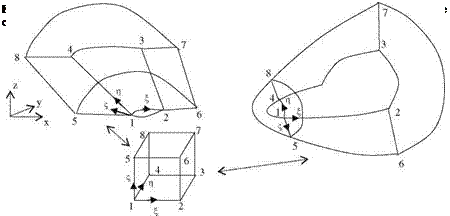
Shown in Fig. 2.6a, b are two different external flow regions: (a) wing upper surface and the boundaries of its computational domain, and (b) half a

fuselage and the computational domain transformed from xyz, Cartesian coordi­nates to ngf, generalized coordinate system. Both flow domains, after the trans­formation in ngf coordinate system, are mapped into the cube denoted by 12345678 for which the discretization of the computational domain becomes straight forward.

In Fig. 2.6, the ng surfaces of physical domain transforms into the square denoted with 1234, wherein, f coordinate of the physical domain is inclined with the body surface, i. e. it is not necessarily normal to the surface. After knowing one to one correspondence of the discrete points of both domains, we can numerically calculate the derivative terms for Пх, Пу, • ••, fz to be used for solving Eq. 2.50 in the discretized cube 12345678. There are quite a few numbers of literature pub­lished about the mesh generation and coordinate transformation techniques, however, two separate works by Anderson and Hoffman can be recommended for beginners and the intermediate level users (Anderson et al. 1984) and (Hoffman 1992).

Energy Equation

The conservation of energy can be formulated with applying the first law of thermodynamics on systems. The system here is in the flow field and receives the heat rate of Q. If the work done by the system to the surroundings is W then the change of total energy in the system becomes

ил, • .

— = Q — W (2.44)

Подпись: Q - W Подпись: ot Подпись: (e + V2/2)p dV+ & (e + V2/2)pV • dA Подпись: (2.45)

At a given time, let the system under consideration coincide with the control volume we choose. If we let Ej denote the internal energy and Ek = V2MV2 the kinetic energy of the total mass in the system, then as the mass independent transferable quantities the specific internal energy becomes e = EJM and the specific kinetic energy reads as Ek/M = VV2. Which means the total specific energy in the control volume is g = e + VV2. Now, we can relate the energy changes of the system and the control volume using Eq. 2.44 in Eq. 2.27 to obtain the integral form of the energy equation

During the flow if we do not provide heat from outside, the system will heat the surroundings by the flux of internal heat from the control surface as follows Q = —&q • dA. On the other hand, the work of the stress tensor throughout the

Подпись: &Подпись:~ • • dA. Now, if we substitute

the integral forms of the heat flux to the surroundings and the work done by the system on the surrounding, Eq. 2.45 becomes

— йq • dA + & (V •Tj • dA = O-JJJ(e + V2/2)p dV + &(e + V2/2)p ~ • dA

(2.46)

Energy Equation Подпись: pe~ Подпись: V • T + q Подпись: 0 Подпись: (2.47)

In Eq. 2.46 we have three surface integral terms. If all three area integrals are changed to volume integrals using the divergence theorem, and all the all volume integrals are collected together over the same control volume, we can write the differential form of the energy equation as follows

Here, s = e + VV2 denotes the specific total energy and Eq. 2.39 defines the stress tensor. The heat flux from a unit surface area reads as

q = — kVT + piUihi + qR + <s’v > (2.48)

Wherein, k denotes the heat conduction coefficient, the second term indicates the heat of diffusion, the third term represents radiative heat flux and the last term shows the turbulence heating. In summary, the global continuity is given by Eq. 2.31, continuity of species by 2.35, global momentum by 2.38 and the energy Equation by 2.47. Let us express these equations in Cartesian coordinates in conservative forms.