Category HELICOPTER AERODYNAMICS

Concept of Helicopter Control

By the term "helicopter control" we mean the actions of the pilot directed toward achieving two objectives: restoration of disturbed equilibrium and

disruption of existing equilibrium. We see that these objectives are

contradictory, but in combination they lead to achievement of the flight objectives.

The actions directed toward restoring disrupted equilibrium of the helicopter are necessary because flight takes place most frequently in rough air, when there is continuous disruption of equilibrium and it must be con­tinuously restored. Otherwise the helicopter cannot fly in the required direction and with the required velocity. The work done by the pilot to restore equilibrium is the primary control work. This operation has recently been mechanized with the aid of autopilots. Helicopter equilibrium is restored by the action of the control moments about the principal axes of the heli­copter.

The control moments are created by the main and tail rotor thrust forces. This means that the helicopter control organs are the main and tail rotors.

The pilot’s actions directed toward disruption of helicopter equilibrium are required when it is necessary to alter the direction or velocity, i. e., alter the flight regime. To change the flight regime it is necessary to change the magnitude and direction of the main rotor thrust force and change the attitude of the helicopter in space, which is achieved by the action of the control moments created by the main and tail rotor thrust forces. This means that in the final analysis helicopter control reduces to control of the main rotor thrust force vector and control of the magnitude of the tail rotor thrust.

The magnitude of the main rotor thrust force vector is changed by changing the collective pitch; the direction of this force vector is changed by changing the main rotor cyclic pitch.

The inertia forces increase the loads on the main rotor blades

Blade Coriolis forces. In addition to the centrifugal forces and the flapping motion inertial forces, there are the rotational inertia forces, or Coriolis forces. They arise as a result of combination of the circular blade motion and blade motion relative to the horizontal hinge axis (flapping motion). As a result of variation of the flapping angle during flapping motions, there is a change of the radius of the circle along which the blade center of gravity travels. Thus, Figure 46a shows that with increase of the flapping angle from 8^ to the radius of the circle described by the blade center of gravity decreases from r^ to r^. Therefore, the flapping motions

The inertia forces increase the loads on the main rotor blades

are associated with radial displacement of the blade mass, and this leads to the development of an inertial force which is termed the Coriolis or rotational force.

The essence of the Coriolis force is easily explained if we recall the /62 nature of inertial forces in the case of rectilinear acceleration of motion. Everyone knows from his own experience that during braking the inertia force is directed forward, and that during rectilinear acceleration it is directed aft. Let us apply this rule to the moving blade.

When upward flapping takes place, the radius of the blade center of gravity decreases, and the circumferential velocity decreases, i. e., retardation of the motion takes place, and an inertial force appears which is directed forward in the direction of rotation of the main rotor.

During downward flapping the radius of the circle along which the blade center of gravity travels increases, the circumferential velocity u = cor increases, and an inertial force directed aft — opposite the rotor rotation — appears.

This analysis is confirmed by the energy conservation law and the associated angular momentum conservation law

m^ur = const

where is the mass of the body;

u is the circumferential velocity; r is the trajectory radius of curvature.

Let us apply this law to blade motion during variation of the flapping angle.

Since the power supplied to the main rotor shaft remains constant, the angular momentum of each blade must also remain constant

Подпись: m, u^r^ = const"bVi =

or

2 2

Подпись:Wi =

After dividing through by m, we obtain = COnst. We see from

this equation that during upward blade flapping (Г2<ґі) the angular velocity must increase or<ler that the angular momentum conservation law not /63

be violated. A force directed along the main rotor rotation is required in order to increase the angular velocity. This force will be the Coriolis or rotational force.

Подпись:is defined as the product of the mass of the body

Подпись: where Подпись: “b jc Подпись: is the blade mass; is the Coriolis acceleration.

Fc = Vc

The Coriolis acceleration is found from the formula

jr = 2wV J C r

where is the relative or radial velocity of the blade center of gravity.

The velocity V (Figure 46a) can be defined as follows :

Vr = Vfl sin g.

Substituting the value of into the formula for the Coriolis acceleration, we obtain

Jc = 2wVfl sin 3.

The formula for the Coriolis force finally takes the form

Fc = 2 F wVfi sin 3’

Thus, the blade Coriolis force is directly proportional to blade weight, main rotor rpm, angular flapping velocity, and the flapping angle.

The Coriolis force for the advancing blade is directed in the direction of rotor rotation and increases as the blade approaches the 90° azimuth. Then it begins to diminish and becomes zero at the moment of equilibrium of the blade relative to the horizontal hinge.

The Coriolis force for the retreating blade will be directed aft, opposing rotor rotation, and reaches its maximal value at the 270° azimuth.

The blade Coriolis force develops the moment = F„r about the

Cor C c. g

main rotor axis (Figure 46b). For the main rotor with diameter D = 20 m without vertical hinges M^, ф 10,000 kgf’m.

Necessity for vertical hinges. We have established that the rotational drag and Coriolis forces act on the blades in the main rotor rotation plane.

At the 90° azimuth these forces are directed in opposite directions (see

Figure 46b). At the 270° azimuth these forces coincide in direction. While

the moment of the Coriolis force alone reaches a magnitude of about 10,000

kgf*m, the combined moment of the two forces (Coriolis and rotational drag)

will be considerably larger. This means that the blade root experiences large /64

loads in the rotor plane of rotation, which can cause rapid failure of the

blade if we consider that these loads alter their sign twice per revolution,

and the magnitude varies from the minimal to the maximal value twice per

revolution.

We encountered the loads created by the blade thrust moment previously.

These loads were eliminated with the aid of the horizontal hinge. In order to eliminate the bending moment in the hub rotation plane from the blade root, we must install a vertical hinge. When this hinge is used, the bending moment at the blade root will be zero, i. e., the blade will rotate forward (in the direction of rotor rotation) or aft about this hinge, performing oscillatory motions.

Vertical rate of climb and its variation with change of flight velocity and altitude

Answer 1. The vertical rate of climb is the altitude which the helicopter gains per second. This rate depends on the excess power and the helicopter weight. The vertical rate of climb decreases with increase of the flight speed and latitude.

Answer 2. The vertical rate of climb is the altitude which the helicopter gains per unit time. The rate depends on the excess power and on the helicopter weight. The excess power increases as the flight velocity is increased from zero to the economical speed. Consequently, the vertical rate of climb will increase. The vertical rate of climb decreases with further increase of the velocity along the trajectory.

The vertical rate of climb increases with increase of flight altitude from zero to the engine critical altitude. The rate decreases at altitudes above the critical altitude.

Answer 3. The vertical rate of climb is the altitude which the helicopter gains per second. This rate will be the higher, the larger the excess power AN and the less the helicopter weight. The excess power decreases with increase of the flight speed; consequently, the vertical rate of climb also decreases.

The power available and the excess power decrease with increase of the flight altitude.

This means that the higher the altitude, the lower the vertical rate of climb. The altitude at which the vertical climbing velocity equals zero is called the helicopter dynamic ceiling.

Techniques for Counteracting Main Rotor Reactive Torque /25

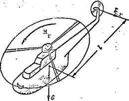
The reactive torque retards rotation of the main rotor and causes the helicopter to turn in the direction opposite that of the rotor. The turning action of the reactive torque is counteracted in various ways. On single­rotor helicopters the reactive torque is balanced by the tail rotor thrust moment (Figure 20).

Since the helicopter turns about its center of gravity, the tail rotor thrust moment is defined relative to the vertical axis of the helicopter.

The helicopter will not turn about the vertical axis if the reactive torque equals the tail rotor thrust moment, which is defined by the formula where Ъ is the distance from the helicopter center of gravity to the tail rotor.

From the formula N = M w we can determine the magnitude of the main req p b

rotor reactive torque and the equal tail rotor thrust moment

N

req _

w


M

r


Techniques for Counteracting Main Rotor Reactive Torque /25

Techniques for Counteracting Main Rotor Reactive Torque /25

Figure 20. Balancing of main rotor reactive moment on a single-rotor helicopter.


Knowing the distance Ъ, we find the tail rotor thrust

M

Подпись:Подпись: t.rt. r.

I ‘

Now it is not difficult to explain the purpose of the helicopter tail rotor. The tail rotor of the single-rotor helicopter is intended to create a thrust whose moment balances the main rctcr reactive torque and thereby pre­vents rotation of the helicopter around the vertical axis. Directional control of the helicopter is accomplished by varying the tail rotor thrust and its moment about the helicopter vertical axis.

In helicopters with two main rotors, the turning action of the reactive torques is automatically eliminated — the main rotors turn in opposite directions and their reactive torques balance one another.

Main Rotor

With regard to the technique used to create and transmit torque, modern helicopters can be divided into two groups:

1) those with reactive drive;

2) those with mechanical drive.

In helicopters with reactive drive the engines are located at the tips

Подпись:Подпись:In this case, the torque can be ex – hy the main rotor

V = P Rk.. tor eng

The torque balances directly the moment resisting rotation; therefore, the helicopter will not turn.

Characteristic for the helicopter with reactive drive are simplicity of its construction and low weight. It has no power expenditure to rotate a tail rotor, less vibration, and there is the possibility of obtaining high main rotor thrust with low thrust of the jet engine located at the tip of the blade.

Any type of reactive engine can be used as the reactive engine at the tip of the blade. However, at the present time the so-called compressor drive is most often used, i. e., reaction nozzles are located at the tips of the blades and are supplied with compressed air from a gas turbine engine or a special compressor.

The reaction-driven helicopter is still in the experimental stage. This is a result of difficult technical problems, the primary ones being:

a) reactive drive; b) mechanical drive;

1) engine gearbox; 2) main transmission shaft; 3) main rotor gearbox; 4) tail rotor d. riveshaft; 5) intermediate gearbox; 6) tail rotor gearbox.

high fuel consumption and low efficiency (2-3%) of the reaction drive;

complexity of the construction of the hub and blades, in which plumbing /27 must be provided;

complexity of the design of a reaction engine which will operate reliably when subjected to the high centrifugal force and the varying airstream direction;

deterioration of the aerodynamic characteristics of the main rotor owing to the engines located on the blades.

Helicopters with mechanical drive are those in which the torque trans­mitted from the engine to the main and tail rotors hy means of a special assembly, termed a transmission (Figure 21b).

The transmission includes the following basic units:

Подпись:F. educers;

Shafts;

Shaft supports and connections;

Airframe-mounted engine reducers; Tail rotor reducers.

Подпись: Main rotor reducers; Intermediate reducers;The main rotor reducer is provided to reduce the rotor shaft speed. The need for this reduction was explained above. Characteristic of this reducer is the high reduction ratio — from 1:8 to 1:14. Two-stage simple reducers are used on light helicopters; usually two-stage planetary reducers are used on the intermediate and heavy helicopters. The torque to the tail rotor is transmitted through the main rotor reducer. When the main rotor turns, the tail rotor is also automatically rotated. Thus, the main and tail rotors always constitute a single system and cannot rotate separately.

The intermediate reducers are installed in order to change the transmission direction (for example, at the juncture of the tail boom and the aft vertical fin). These reducers do not change the rpm., and consist of two conical gears.

The airframe-mounted engine reducers are used to transmit the torque from the horizontal engine shaft to the vertical transmission shaft. They are located in the engine case, and are used when the engine shaft axis is horizontal.

The tail rotor reducers are provided to transmit torque to the tail rotor /28 shaft and to reduce tail rotor shaft rpm. The mechanism for controlling the tail rotor is located in its reducer.

The torque is transmitted by the transmission shafts. The transmission of a single-rotor helicopter includes:

Main transmission shaft;

Tail rotor driveshaft.

The main transmission shaft transmits the torque from the engine to the main rotor reducer.

As a rule, the tail rotor driveshaft consists of several sections and transmits the torque from the main rotor reducer to the tail rotor reducer and Its length is 8-10 m. This shaft is a source of additional vibration of the helicopter.

Подпись: N req Подпись: = M ш, tor Подпись: then M tor Подпись: N rec . 0)

All the transmission shafts rotate at high angular speed. Increase of the angular speed reduces the loading on the shaft for transmission of the same power.

The shaft supports prevent deflection and bending vibrations (whipping) of t. he long shafts. Ball bearings with elastic spacers are used as the supports. The shafts are connected with one another and with the other parts of the transmission by means of universals and flexible couplings; in addition to the interconnecting couplings there, are starting, engaging, and freewheeling clutches.

On some helicopters all three of these clutches are combined into a single, unit, located in the engine case together with the reducer. The free­wheeling clutch is most frequently made in the form cf a separate unit. The starting clutch is a unit of the friction type and is intended for smooth connection of the transmission shaft with the engine shaft. When this type of connection is used, there is slippage of one shaft relative to the ether until the speeds of the driving and driven shafts become the same. This clutch transmits the small torque from the engine to the transmission when the engine is operating at low speed. The starting clutch provides smooth rotation of the main and tail rotors without jerking. When the transmission is engaged, the main clutch (most often of the dog type) is activated and connects the engine and transmission shafts rigidly together. The total torque is transmitted from the engine to the main and tail rotors through this

clutch. The freewheeling clutch is designed to transmit torque in one direc­tion only — in the direction of rotation of the rotor. It provides automatic disconnect of the engine from the transmission if there is a reduction of the engine rpm. This is necessary in the main rotor autorotation regime if there is an engine failure in flight. Moreover, the presence of the freewheeling clutch leads to reduction of the inertial loads on the main rotor shaft when there is a change of engine operation. As a rule, the freewheeling clutch is located in the main rotor reducer case, between the main transmission shaft /29

and the reducer shaft. The main rotor brake is designed for rapid deceleration of the transmission after shutting down the engine on the ground.

The helicopter transmission is quite heavy, and therefore reduction of the weight of its individual components is of primary importance.

Vortex Ring Regime

During helicopter vertical descent the air flow accelerated downward by the rotor increases its velocity from V_^ to 2V^ at a distance from the main rotor equal to about 2R. With further distance from the main rotor the flow decreases its velocity to as a result of "friction" with the opposing air (Figure 58a).

If the flow velocity V3 equals the helicopter vertical descent velocity

V, , the velocity of the flow accelerated by the rotor V„ = 0, i. e., the /86

des 3

rotor essentially "catches" the air which it has accelerated. As a result of inflow above the rotor there will be an "interface" where the rotor essentially "runs away" from the inflowing air with the same velocity. This means that two interfaces are formed: below and above the rotor. At these

surfaces the flow leaving the rotor turns and forms closed vortices, which have nearly no effect on thrust formation, since they are far from the rotor.

As the vertical descent velocity is increased, the interfaces where Vg = approach the main rotor. The vortices become more intense and

unstable. The rotor expends the power obtained from the engine on rotation of these vortices. The main rotor thrust decreases sharply, since air is not ejected from the closed vortex system (Figure 58b). The vertical descent velocity increases still further. The helicopter begins to toss from side to side, control of the helicopter becomes difficult, and heavy buffeting appears. This flight state corresponds to the developed vortex ring regime.

The vortex ring regime occurs with vertical descent at a velocity more than 2-3 m/sec with the engine operating.

The most effective technique for recovery from the vortex ring state is to transition the main rotor into the autorotation regime along an inclined trajectory. But this requires considerable altitude and the absence of obstacles, therefore, the vortex ring regime is dangerous and must be avoided.

What determines the blade element autorotation conditions?

Answer 1. The blade element autorotation conditions are determined by the inclination of the elemental aerodynamic force relative to the main rotor hub axis. If the force is directed parallel to the hub axis, its projection on the plane of rotation equals zero, and the autorotation will be steady-state.

If the force vector AR is inclined forward relative to the hub axis by the angle y, the autorotation will be accelerated. If the force vector AR is inclined aft by the angle y, the autorotation will be decelerated. The inclina­tion of the vector AR depends on the blade element pitcn and angle of attack increment (Да = arc tg /u) . The lower the pitch and the larger Act, the larger the forward tilt of the vector AR.

Answer 2. The blade element autorotation conditions are determined by the aerodynamic efficiency К = Y/X. The higher the aerodynamic efficiency, the smaller the aerodynamic efficiency angle 0^, the larger the forward tilt of the force vector AR, and the higher the main rotor rpm will be. Since the

aerodynamic efficiency and the efficiency angle depend on the angle of attack, the autorotation conditions are determined by the angle of attack. At the optimal angle of attack, the force vector AR has the maximal forward tilt, therefore, the autorotative regime will be accelerated. At angles of attack greater than and less than the optimal value, the blade element autorotation will be decelerated.

Answer 3. The blade element autorotative conditions are determined by the tilt of the elemental resultant aerodynamic force R relative to the main rotor hub axis. If this force vector is tilted forward, the blade element will have accelerated autorotation; if it is tilted aft the autorotation will be decelerated. If the direction of AR is parallel to the hub axis, the autorota­tion is steady-state. The tilt of the force AR depends on the angle of attack increment Да formed as a result of the vertical rate of descent (Да = arc tg ^des^Ur0" .The higher the vertical rate of descent, the larger Да, the larger the tilt of the force AR, and the higher the main rotor rpm.

Drawbacks of Main Rotor with Rigid Blade Retention

The main rotors of the early helicopters (TsAGIl-EA, for example) had blades which were rigidly attached to the hub. The blade incidence angle was changed by means of axial hinges. In their arrangement such rotors are similar to airplane variable pitch propellers. But the very first flights disclosed major deficiencies characteristic of these rotors.

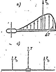
The thrust is created by all the blade elements, but the highest elemental forces will be those on the elements located at 3R/4 (see Figure 15d). The resultant of the elemental forces is applied at the blade center of pressure, which is located at the element with relative radius r = 0.7. This distribu­tion of the elemental thrust forces and this positioning of the resultant leads to the creation of a large bending moment at the blade root (Figure 34a). The approximate magnitude of the blade root bending moment at the blade

attachment to the hub is determined from the formula M, , = T, 0.7R.

Dend b

Thus, if the rotor has four blades and the helicopter flight weight is 6000 kgf, the thrust of a single blade will be = 6000:4 = 1500 kgf. For main rotor diameter D = 20 m, М^еп^ = 1500 x 0.7 x 10 = 10,5000 kgf’m. This moment will be still larger for a heavy helicopter. The large bending moment creates a large load on the blade root. Moreover, the blade is subjected to a centrifugal force which reaches a magnitude of several tens of tons ; con­sequently the root portion of the blade operates under conditions of large loads. In order to avoid blade failure, the area of its root section must be increased, and this leads to increase of the structural weight and reduction of the helicopter’s useful load.

Since the blade thrust varies azimuthally, its bending moment also varies (Figure 34b). The variable bending causes fatigue stresses in the material of the structural elements, which can lead to rapid blade failure. The up and down bending vibrations of the blade tips reach high frequencies (up to 3-4 cycles per second), creating heavy vibration of the helicopter.

The blade thrust does not vary azimuthally in the vertical flight regime, and this means that the main rotor thrust vector, equal to the sum of the blade thrust forces T = T^k, lies along the hub axis (Figure 34c).

In the forward flight regime the blade thrust depends on the azimuth. /49

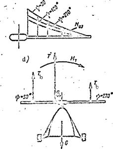
The thrust is maximal at the 90° azimuth and minimal at the 270° azimuth (Figure 34d). As a result of this variation, half the main rotor disk (advancing blades) has a higher thrust than the other half, formed by the retreating blades.

In this case the main rotor thrust vector T does not pass through the center of the hub, but rather at the distance a from the hub axis. The thrust moment ftL, = Та is created relative to the hub axis.

Drawbacks of Main Rotor with Rigid Blade Retention

ю


Figure 34. Blade bending moment and main rotor thrust overturning moment.


Drawbacks of Main Rotor with Rigid Blade Retention

Since the hub axis is in the helicopter plane of symmetry, the main rotor thrust moment causes the entire helicopter to tend to overturn. This is termed the overturning moment. Thus the main rotor with rigid blade restraint has three major drawbacks:

presence of the overturning thrust moment in the forward flight regime; presence of large thrust bending moment at the blade root; variation of the blade thrust moment azimuthally.

All these drawbacks can be eliminated if the blades are attached to the hub by means of horizontal hinges.

Effect of flight altitude and air temperature on helicopter flight characteristics

Answer 1. Increase of the flight altitude involves reduction of the air density. This leads to reduction of the thrust developed by the main rotor. Since the horizontal flight condition is the equality G = Y, with increase of the altitude the induced velocity must be increased; therefore, the induced power NL = GV^ will increase. The power required curve is shifted upward for low flight speeds.

Подпись: /102At high flight speeds, the induced power increases only slightly, while the power required for motion decreases with increase of the altitude ; there­fore, at high speeds the power required curve is shifted downard. As a result of this change of the power required and available, the minimal and maximal horizontal flight speeds increase up to the engine critical altitude. Above the critical altitude the maximal flight speed will decrease. Increase of the air temperature is equivalent to increase of the altitude.

Answer 2. With increase of the altitude the power required for helicopter horizontal flight increases. The power developed by the engine decreases. The power required curves are shifted upward and the power available curves are shifted downward. As a result of this displacement of the curves, the maximal speed decreases and the minimal increases; the speed range and the excess power decrease. Increase of the air temperature leads to reduction of the power required and available.

Change of Main Rotor Collective and Cyclic Pitch

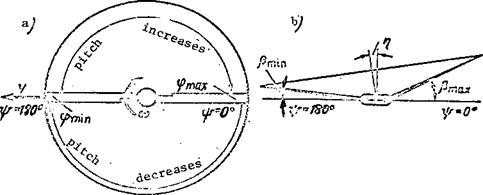
Simultaneous rotation of all the blades relative to the axial hinges in the same direction and through the same angle is termed collective pitch change. Increase of the collective pitch leads to increase of the main rotor thrust force. Sequential change of the blade pitch in azimuth is termed cyclic

pitch change. During cyclic pitch change, the pitch of each blade increases over a 180° azimuth range and decreases in the other half of the circle (Figure 104a).

Change of Main Rotor Collective and Cyclic Pitch

Figure 104. Main rotor cyclic pitch variation.

When the pitch is changed, the blade thrust changes and its moment about the horizontal hinge changes, which leads to flapping motions and tilt of the cone-of-revolution axis and deflection of the thrust force vector.

If the thrust force vector needs to be deflected in the direction of the 210° azimuth, the blade pitch must be minimal at this aximuth and maximal at the opposite azimuth — 30°. Then the pitch decreases from the 30° azimuth to the 210° azimuth and increases from the 210° azimuth to the 30° azimuth.

A similar pitch change is observed for each blade. Change of the collective and cyclic pitch is accomplished with the aid of a special system — the main rotor tilt control.

Oscillatory Blade Motions

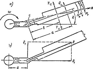
The vertical hinges have stops to limit the oscillatory motions of the blade. However, the blade does not reach the stop in flight, since equilibrium is established under the influence of the moments of the forces acting on the blade in the main rotor hub rotation plane (Figure 47a).

The condition for equilibrium relative to the vertical hinge in general form is expressed by the equality

ХЛ.Н – °-

For a positive lag angle, this equality can be written as

Oscillatory Blade Motions

Figure 47. Blade equilibrium about vertical hinge.

MN = MQ±MP.

The lag angle is the angle £ between the radial line and the longitudinal /65 axis of the blade. The radial line is the line passing through the main rotor axis and the vertical hinge axis.

The lag angle will be positive when the blade rotates aft relative to the radial line, opposite the main rotor rotation. In the last equality, the blade centrifugal force moment = Nc will be larger, the larger the centrifugal force and the larger the lag angle. With increase of the lag angle there is an increase of the centrifugal force arm c and its moment relative to the vertical hinge.

For a positive lag angle, the moment rotates the blade ahead in the direction of rotation of the main rotor about the vertical hinge.

If the lag angle is negative, the centrifugal force moment rotates the blade aft, opposite the direction of rotation of the main rotor. Therefore, the centrifugal force moment rotates the blade toward the radial line: it

acts as a sort of regulator of the oscillatory motions. Under the influence of this moment, the positive lag angles £ do not exceed 3-5° (with the main rotor driven by the engine). Negative blade lag angles are developed when the main rotor operates in the autorotation regime. In this case, the lag angles reach 8-12°.

The moment = Qa of the rotational drag force always opposes rotation of the rotor. Since the force varies with azimuth, its moment will also vary.

The Coriolis force moment M^, = F^b varies as a function of azimuth, both in magnitude and direction. At azimuth angles close to 90° the Coriolis force reduces the lag angle, while at azimuths close to 270° the lag is increased.

Now (18) can be written in expanded form

Nc = Q^a + Fcb = 0.

This will then be the condition for equilibrium of the blade relative to the vertical hinge.

The moments and vary continuously in azimuth, and their variation is one of the reasons for the oscillatory motions of the blade relative to the vertical hinge in the forward flight regime.

Another reason for the oscillatory motions is the action of the centrifu­gal force and its moment relative to the vertical hinge. Its action can be compared with the action of the weight force on a freely suspended body.

If a freely suspended body is deflected, oscillations similar to those of a pendulum develop.

Since the centrifugal force is several times stronger than the weight force, it creates significant "pendulous" oscillations, which combine with the oscillations from the variable moments of the rotational drag force and the Coriolis force to amplify or attenuate the amplitudes of the blade /66

oscillations about the vertical hinge.