Category HELICOPTER AERODYNAMICS

Horizontal Flight Endurance and Range

Horizontal flight endurance is the time in the course of which the heli­copter can perform horizontal flight using the available fuel supply. Flight endurance is found from the formula

T = Gfuel
hr" %

where the fuel supply for horizontal flight, liters;

c^ is the fuel consumption per hour, liters/hr.

This formula shows that the endurance depends on the fuel supply and the hourly consumption. The fuel supply for horizontal flight is the

difference between the amount of fuel serviced into the tanks G and the amount of fuel expended in the other flight regimes: taxiing, takeoff, climb,

descent, and landing. The fuel consumption in these flight regimes is indi­cated in the instructions for calculating flight endurance and range, which are prepared for each helicopter type on the basis of calculations and flight tests.

Подпись: г
The hourly fuel consumption is the amount of fuel which the engine consumes per hour of operation. It is found from the formula

= = <29)

where ce is the specific fuel consumption;

N is the effective engine power; e

C, is the power utilization coefficient.

Since c£ and £ change only slightly with variation of the flight speed, their ratio can be assumed constant and (29) takes the form

ch = const /Vh.

This formula shows that the hourly fuel consumption depends on the /99

power required for helicopter horizontal flight, and consequently, on the flight speed.

Using the curve of power versus speed (see Figure 62), we can say that the minimal power required for horizontal flight corresponds to the economical speed; therefore, the minimal hourly fuel consumption corresponds to this speed.

In order for the helicopter to stay in the air for the maximal time, flight must be performed at the economical speed. The economical speed depends on helicopter weight: this speed increases with increase of the weight, and

the flight endurance decreases. Since the economical speed changes very little with altitude, the horizontal flight endurance decreases somewhat with increase of the altitude as a result of the increased fuel consumption in climb and descent.

Helicopter horizontal flight range is the distance which the helicopter can fly while utilizing the fuel supply for horizontal flight

(ЗО)

Horizontal Flight Endurance and Rangewhere is the fuel consumption per kilometer, liters/km.

The horizontal flight range is larger, the larger the fuel supply and the lower the consumption per kilometer. The fuel supply is defined as in the flight endurance calculation. The consumption per kilometer is found from the formula

c* ^ if – = const ~r~.

The minimal fuel consumption per kilometer will be achieved with the

minimal ratio N, /V.

n

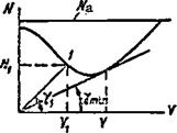
Let us examine the power required and available curves for horizontal flight (Figure 66). Any point on the power required curve corresponds to definite values of V and N. For example, the point 1 corresponds to the speed V^, and the power required N^. The ratio of these quantities is equal to tg Y, and therefore, the consumption per kilometer is

= const tg

This means that tg у must be minimal in order to obtain the minimal fuel con­sumption per kilometer. This corresponds to the angle between the tangent to the power required curve and the horizontal axis. The point of tangency will correspond to the optimal helicopter horizontal flight speed.

Thus, the maximal horizontal flight range is achieved at the optimal

speed, which corresponds to the minimal fuel consumption per kilometer only if the engine is carefully adjusted. In this case, the calculation of the maximal range is made using the fuel consumption per kilometer curves plotted

on the basis of experimental helicopter operational data. The speed obtained from these curves and the corresponding minimal consumption will be close to the optimal values.

Подпись: optПодпись: Figure 66. Dependence of N/V on flight speed.Horizontal Flight Endurance and RangeThe consumption per kilometer is the fuel burned per kilometer of air distance (relative to the air). Con­sequently, the flight range calculation made using (30) is valid only if there is no wind. If there is wind, the

flight range will vary, depending on the wind direction and velocity. The so – called navigational fuel supply, amounting to 10-15% of the required fuel, is set aside as reserve in case the weather conditions change. Since the power required for horizontal flight depends on helicopter weight and flight altitude, the fuel consumption per kilometer increases, and the range decreases with increase of the weight. The average flight weight is used for exact range calculations

Horizontal Flight Endurance and Range

G = G av to


where G is the takeoff weight;

Gf і is the fuel supply for horizontal flight.

With increase of the altitude the optimal speed increases somewhat, and the power required decreases, therefore, the fuel consumption per kilometer also decreases. But the climb to a higher altitude requires more fuel. In practice, the longest flight range without account for wind is obtained at an altitude from 1000 to 2000 meters. For the Mi-1, the minimal fuel consumption per kilometer is 0.56 liters/km at an altitude of 1000 meters and an indicated airspeed of 130 km/hr. The flight range with this fuel consumption rate is 370 km.

Helicopter Dynamic Stability

General analysis of dynamic stability. While static stability defines the attitude stability, dynamic stability defines the nature of the helicopter motion after disruption of equilibrium. In equilibrium the helicopter travels in a straight line with constant velocity and without rotation. Such motion is called undisturbed. If equilibrium is disrupted, the helicopter rotates about its axes and the flight velocity and direction change. This motion is called disturbed. Disturbed motion may be either aperiodic or oscillatory.

Aperiodic motion is motion in one direction from the equilibrium position. For example, when equilibrium is disturbed the helicopter center of gravity deviates (Figure 101, solid line). After elimination of the factor causing disruption of the equilibrium, the nature of the disturbed motion may differ.

Helicopter Dynamic Stability

Figure 101. Dynamic stability.

If the center of gravity approaches the line of unperturbed motion (Figure 101a, dashed line), the helicopter has aperiodic stability; if the

helicopter center of gravity continues to deviate further from the equilibrium line (Figure 101b) the helicopter has aperiodic instability. Oscillatory motion is periodic back-and-forth motion relative to the equilibrium line.

If after disruption of equilibrium the helicopter center of gravity travels along a wave-like curvilinear trajectory and this motion is damped, the helicopter has oscillatory dynamic stability (Figure 101c). If the amplitude of the disturbed oscillatory motion increases, the helicopter has dynamic instability or oscillatory instability (Figure lOld).

Most frequently the disturbed motion of the helicopter is oscillatory, and the oscillations will be complex, since the helicopter oscillates simul­taneously about all axes. Moreover, the short and long periodic oscillations are superposed on one another. The short-period helicopter oscillations are those about the center of gravity with account for the influence of the main rotor damping moment; the long-period oscillations are those about a center located at a considerable distance from the helicopter.

Helicopter transverse oscillations in the hovering regime. Let us

assume that the helicopter banks to the angle у in the hovering regime (Figure

102 a). We resolve the helicopter weight force into the components:

acting in the plane of symmetry, and G2 perpendicular to this plane. The

force = G sin у is unbalanced and causes sideslip of the helicopter. As

a result of the increase of the sideslip velocity, the main rotor cone-of-

revolution axis will tilt to the side opposite the slip (Figure 102b). The

force Px is created, which reduces the sideslip velocity and the moment of this

force reduces the bank angle. But the force P is less than the force G„;

о x 2

therefore, the sidelsip velocity will increase and the velocity will be maximal at the moment the helicopter arrives at the position shown in Figure 102 c.

Подпись:The helicopter continues its motion in the same Then the force G2 changes from driving to retarding,
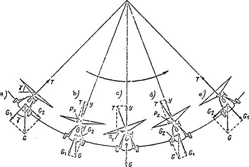
Helicopter Dynamic Stability

Figure 102. Helicopter lateral oscillations.


Подпись:decreases. As a result, the tilt of the cone-of-revolution axis decreases and the moment of the force P^ about the longitudinal axis banks the heli­copter in the opposite direction. When the helicopter reaches its maximal deviation (Figure 102e) further motion terminates. The cone-of-revolution axis coincides with the huh axis and the force P =0. But the force G

X /.

reaches a maximum and causes motion in the reverse direction and the whole cycle repeats. This transverse rocking of the helicopter will increase continuously, and the helicopter will turn over if these oscillations are not terminated in time.

We have examined in this example only the transverse oscillations, but in reality the transverse oscillations are supplemented by longitudinal and directional oscillations; therefore the pattern of the oscillatory motions will be more complex.

Longitudinal oscillations of helicopter in flight with horizontal velocity. If the longitudinal equilibrium of a helicopter is disturbed, longitudinal oscillations develop (Figure 103),i. e., the helicopter will travel along a wave-like trajectory. The existence of such oscillations is confirmed by flight tests in which automatic instruments record the nature of the helicopter oscillations about all axes. The longitudinal oscillations have a considerably longer period (total oscillation time) than the transverse oscillations. The amplitude of the longitudinal oscillations increases in the course of time, although more slowly than the amplitude of the transverse oscillations. Helicopter oscillations about the vertical axis also take place; however, they are performed with a period longer than the transverse oscillations but shorter than the longitudinal oscillations.

Helicopter Dynamic Stability

Figure 103. Helicopter longitudinal oscillations.

From this analysis we can conclude that the helicopter has dynamic instability. Therefore, if the equilibrium of the helicopter is disturbed it will have an oscillatory motion with increasing amplitude and cannot by itself eliminate these oscillations. This means that in every case of equilibrium disruption the pilot must take measures to restore the equilibrium, i. e., he must control the helicopter.

Helicopter Forced Vibrations

There are in the helicopter many sources of exciting forces which cause forced vibrations. Such sources include: main and tail rotors, powerplant,

transmission gearboxes, and transmission shafts.

Each of these sources creates exciting forces with a definite frequency.

The lowest exciting force frequency is that of the main rotor. It may be found from the formula

where n^r is the main rotor exciting force frequency; ng is the main rotor rps; к is the number of main rotor blades.

The frequency of the main rotor exciting forces varies in the range of 8-16 vibrations per second. The tail rotor excites forces with a frequency of 10 – 60 vibrations per second. The transmission shafts and gearboxes create a still higher frequency of the exciting forces: from 50 to several

hundred vibrations per second. The powerplant yields a broad spectrum of exciting forces with frequency of 600 – 1000 vibrations per second.

The primary forced vibration source is the main rotor with hinged blade support. Blade oscillations relative to all the hinges are also the source of many vibrations.

26k


Vibrations from the blades of the main and tail rotors are transmitted through the hubs and the airstream deflected by the blades. This slipstream strikes the tail boom and tail fin in the form of periodic pulses and causes vibrations.

All parts of the helicopter are subjected to forced vibrations, but the amplitude of these vibrations differs. The amplitude magnitude depends on the stiffness of the structure, the closeness of the source of the exciting forces, their magnitude and points of application, and on the degree of close­ness to resonance. The degree of closeness to resonance is determined by the relative frequency v, equal to the ratio of the exciting force frequency to the natural vibration frequency

v = —- •

n

nat

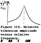
The amplitude of forced vibrations can be expressed graphically, plotting the structure deformation vertically and the relative frequency horizontally (Figure 110). The relative deformation is the ratio of the deformation caused /180 by the dynamic load to the deformation created by the static load. From this graph we can draw the following conclusions:

The largest deformation or the largest amplitude occurs at resonance (v = 1). Therefore, resonant vibrations are very dangerous: they can lead

to structural failure due to material fatigue;

For v > 0.5 the vibration amplitude increases very rapidly and the structural deformation increases sharply;

For v > 1.5 there is a reduction of the structural deformation in com­parison with the deformation caused by a static load of the same magnitude.

Thus, to reduce the structural deformation it is necessary to reduce the degree of closeness to resonance by altering the natural vibration frequency.

If the exciting force frequency is high, the natural vibration frequency must be reduced. Rubber vibration dampers are used in mounting the engine to the frame to avoid resonance. The use of shock mounts reduces the stiffness of the frame-engine structure, which leads to reduction of the natural vibration frequency and increase of the relative frequency (v > 1.5).

Подпись: ; ^dyn 11 і' Figure 110. Relative vibration amplitude versus relative frequency. 0 0.5 1 1.5 V Another example. The main rotor provides low-frequency exciting forces. The main rotor gearbox is mounted rigidly to the gearbox frame, without shock absorbers. This type of mounting increases the natural vibration frequency, and as a result the relative frequency is considerably less than
0.5.

Helicopter Forced Vibrations

The helicopter control linkage rods are most frequently subjected to forced vibrations. Therefore, it is particularly important to prevent resonance of the control rods. To this end the natural frequency of the rod is determined. If this frequency is close to the exciting force frequency in the region where the rod is located, the natural frequency must be changed. This frequency can be found from the approximate formula

where D is the rod cross-section diameter; l is the rod length;

E is the longitudinal elastic modulus; у is the specific weight of the material.

We see from this formula that the rod diameter must be increased or its length must be reduced in order to increase the natural vibration frequency.

If the rods are long, roller type supports are used to increase the frequency. When it is not possible to determine exactly the possibility of the occurrence of resonance, use is made of rods with inertial dampers. The inertial damper is a weight located inside the rod close to its midpoint, between two rubber plugs. The presence of the damper leads to rapid decay of the vibrations.

Under normal conditions the forced vibrations of the various parts of the helicopter are small; their amplitudes are measured in hundredths or tenths of a millimeter. However, in certain cases they may become hazardous if the normal operating conditions are exceeded.

Most frequently, magnification of the vibrations is caused by the failure of individual structural elements (stiffness is reduced and resonance occurs), by improper the adjustment of structural parts, and by mass unbalance. The acceptable vibration limit is determined by their effect on the structure and on the human organism. Vibrations are considered acceptable if they do not lead to structural failure and do not cause discomfort to the personnel (Figure 111). The higher the vibration frequency, the lower the vibration amplitude which can be endured by the personnel without pain.

Inertial Forces Acting on Main Rotor Blades

As a result of rotation of the main rotor, centrifugal forces, whose magnitude we have already determined, act on the blades.

As a result of the flapping motions, inertial forces develop in the plane perpendicular to the main rotor plane of rotation. The flapping motion inertial forces change their direction and magnitude as a function of blade azimuth.

At azimuths from 270° to 90° the inertial forces of the flapping motions are directed downard. These forces reach their maximal magnitude at an azimuth close to 360°, since the maximal upward acceleration of the blade occurs at this point. At azimuths from 90°to 270° the inertial forces are directed upward and have their maximal magnitude at the 180° azimuth, when the blade acceleration downward will be greatest. At the 90°and 270° azimuths the flapping motion inertial forces are zero, since the flapping motion accel­erations are zero at these azimuths, and the flapping motion velocities are maximal.

Power required for helicopter climb and descent along an inclined trajectory

Answer 1. The power required for climb and descent consists of three parts: the power required to overcome profile drag, for horizontal motion of

the helicopter, and for vertical motion of the helicopter.

Daring constant-velocity flight the profile power remains the same in all regimes. The power required for horizontal displacement also remains constant both for horizontal flight and for climb and descent. The power expended on vertical displacement will be more during climb, and less during descent. The sum of all these parts, i. e., the power for the given regime, will be practi­cally the same in all regimes and varies with variation of the flight speed.

Answer 2. The power required for climb and descent along an inclined trajectory consists of three parts: the power required to overcome the profile

drag; the power to create the lift force equal to the helicopter weight; and the power to overcome helicopter parasite drag.

During flight at constant speed the profile power remains constant in all regimes. The power required to create the lift force during climb will be more, and during descent will be less than in horizontal flight. If the velocity is unchanged, then the power required to overcome the parasite drag will remain unchanged. Consequently, the power required for climb is more than that for horizontal flight, while the power required for descent is less.

Answer 3. The power required for climb and descent along an inclined trajectory consists of three parts: the power required to overcome the profile

drag, the power for creating the lift force, and that for motion of the helicopter along the given trajectory.

The profile power remains practically unchanged if the main rotor rpm remains the same in the various flight regimes. During climb and descent (climb and descent angles no more than 10°) the induced power remains unchanged and practically equal to the induced power for horizontal flight. The power required for motion during climb is more than the power required for motion in /114 horizontal flight by the magnitude of the excess power AN, i. e., N ^ = N^ + AN, and the power required for motion during descent is less than the power required for horizontal flight by the amount AN.

Main Rotor RPM Control

The main rotor rpm will change both with change of the power supplied,

i. e., the engine power, and with change of the power required, i. e., with change of the main rotor reactive torque. The magnitude of the thrust devel­oped by the main rotor changes with change of the rpm.

We need to know the optimal rotor rpm, i. e., is it better to increase the thrust by increasing rpm or pitch? Moreover, we need to know how to maintain the optimal main rotor rpm with variation of the magnitude of the thrust.

The answer to the first of these questions can be obtained by examining the characteristic termed specific thrust. Main rotor specific thrust is a quantity equal to the ratio of the thrust developed by the rotor to the power required to turn the rotor

T

q = N • (12)

req

The specific thrust shows the number of units of thrust per unit of /24

power expended by the engine in turning the rotor. The larger the specific thrust, the more efficient the main rotor.

We substitute the values of the thrust from (8) and the power required from (10) and (11) into (

Consequently, to increase the thrust we should reduce the main rotor tip speed. This means that it is better to increase the thrust by increasing the main rotor pitch at minimal rpm. Here, it must be emphasized that there is a minimal permissible rpm for every rotor. Reduction of the rpm below the minimal acceptable value leads to flight safety problems, deterioration of helicopter controllability and stability.

This conclusion is very important, as it provides an answer to the question of why heavy and complex main rotor reduction gearboxes are installed in helicopters. These reducers make it possible to connect the main rotor shaft, which rotates at a low angular velocity, with the engine shaft, which rotates with an angular velocity 10-15 times that of the rotor.

Thus, we have established that it is advisable to turn the main rotor at low speed and increase thrust by increasing the pitch. But increase of the pitch leads to increase of the reactive torque and, therefore, increase of the power required. This means that in order to maintain constant rotor rpm

the power supplied to the rotor must be changed at the same time the pitch is changed. The main rotor and the engine must be controlled simultaneously. Simultaneous control is accomplished with the aid of a special lever, termed the "collective-throttle" lever. This lever is installed in an inclined position to the left of the pilot’s seat. If the collective-throttle lever is displaced upward, both the main rotor pitch and the engine power are increased simultaneously, and the main rotor rpm remains approximately constant. The throttle twist grip is located on the end of this lever. The engine power alone, and therefore the main rotor rpm, can be altered by rotating this grip.

Helicopter Vertical Descent With Operating Engine

Helicopter flight downward along a vertical trajectory is termed the vertical descent regime. In this case the following forces act on the heli­copter (Figure 57): the helicopter weight G, main rotor thrust force T, and

tail rotor thrust T.

t. r

The vertical descent conditions /85


Figure 57. Forces acting on heli­copter in vertical descent.


Helicopter Vertical Descent With Operating Engine

EM = 0. eg

Here we must bear in mind that

we neglect the parasite drag force in view of its small magnitude, and we assume that as a result of the small tilt of the cone axis to the side TTaY.

In transitioning from the hovering regime to the vertical descent regime, the main rotor pitch must be decreased and in so doing the main rotor thrust force is also reduced. However, as soon as the helicopter transitions into descent the blade element angles of attack increase, which leads to increase of the thrust force to the value present prior to reducing the pitch. Thus, the condition T.= G holds for both hovering and vertical descent.

The power required for vertical descent is defined just as in the other vertical regimes

Подпись:= N. + N

pr

i. e., it is equal to the sum of the induced and profile powers. At constant rpm the profile power is practically independent of main rotor pitch, con­sequently N = N. The induced power in descent is defined as

prdes prhov

Ї. = T(V. – V, ) .

x. і des

des

During descent less power is required to satisfy the condition T = G than is required in hover.

Helicopter Vertical Descent With Operating EngineHelicopter Vertical Descent With Operating Engine

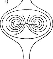
Figure 58. Formation of vortex ring.

Gliding Characteristics of Dual-Rotor Helicopters

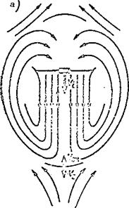
Gliding of dual-rotor helicopters in the autorotative regime has certain peculiarities in comparison with the single-rotor machines. In the dual-rotor helicopter with tandem rotors, the air flow approaches the forward rotor at a large angle of attack and the aft rotor at a smaller angle (Figure 86a). The

Gliding Characteristics of Dual-Rotor Helicopters

Figure 86. Dual-rotor helicopter gliding characteristics.

angle of attack change takes place because of deflection of the flow by the forward rotor. In the dual-rotor helicopter with coaxial rotors, the lower rotor deflects the flow approaching the upper rotor, which leads to reduction of the angle of attack of the upper rotor (Figure 86b).

The reduction of the angle of attack of the aft rotor in the tandem arrangement and of the upper rotor in the coaxial helicopter leads to reduction of the axial component of the approaching flow and to reduction of Да of the blade elements. Consequently, the aft rotor will operate under conditions of decelerated autorotation. Moreover, along with the angle of attack decrease there is a decrease of the thrust force of the aft rotor. It is necessary that the thrust forces of the two rotors be the same in order to maintain equilibrium of the helicopter. In order to increase the thrust force of the aft rotor, its pitch must be increased, which leads to still greater deceleration of its rotation.

Since the two rotors must rotate in exact synchronism, their autorotative conditions will be different. The front rotor will operate under accelerated autorotative conditions while the aft operates under decelerated conditions, i. e., the front rotor "leads" the aft rotor (it creates the driving torque for the aft rotor). As a result of the driving torque and friction in the trans­mission components, the front rotor develops a yawing moment which causes the helicopter to turn in the direction of rotation of the front rotor. The aft rotor develops a reactive torque, which also causes the helicopter to turn in

the direction of rotation of the front rotor. The helicopter will tend to yaw when gliding. This yawing is eliminated by deflecting the axes of the main rotor cones in opposite directions. Therefore, control of the helicopter during gliding is difficult.

The upper rotor of the coaxial helicopter also operates under decelerated autorotation conditions. Consequently, the lower rotor must develop the driving torque for the upper rotor. Here again, yawing of the helicopter in the direction of rotation of the lower rotor develops. This is eliminated by deflecting the directional control. Control of the coaxial helicopter in a glide is also more complex than control of the single-rotor helicopter.

In conclusion, we note that on all helicopters gliding is performed at a considerably lower speed than used for horizontal flight. The reduction of the gliding speed is explained by the onset of flow separation. Since the flow approaches the main rotor from below, the angles of attack of all the blade elements will be greater than in horizontal flight. Therefore, the blades reach their stalling angle at the ф = 270° azimuth at a speed considerably lower than in horizontal flight.

Variation of Circumferential and. Resultant Velocities along Main Rotor Radius

Let us examine the velocity diagram of different blade elements of a two – bladed rotor when the blades are at the 90° – 270° azimuths. We shall consider the vectors of the reversed flow, i. e., the velocity vectors of the flow which approaches the blade element as a result of the circumferential velocity and the flight velocity. The velocity vectors of the motion of a point on the blade element were shown previously in Figure 32a, b.

In the diagram of Figure 33 we examine the reversed vectors. We see the following from the figure.

1. The circumferential velocities increase from zero at the hub axis.

The variation of the circumferential velocities of the various elements up to the maximal value at the tip elements is shown along the line OD or OE.

2. All the blade elements travel with the velocity of the helicopter.

If we draw the line FG parallel to the line ED at the distance V, we obtain the diagram of the resultant velocities of the various elements.

3. At the 90° azimuth the resultant velocity of all the elements is u + V = шг + V; at the point 0, W = V.

4. At the 270° azimuth the resultant velocity is cor – V.

5. At the outboard blade elements, located between points A and C, the circumferential velocity is greater than the flight velocity and, consequently,

the difference u – V is positive, i. e., W > 0. Therefore, the air flow /47

approaches the outboard elements from the leading edge. There is direct flow over the blade elements just as at the 90° azimuth, but with a lower velocity.

6. The blade element located at the point A has a circumferential velocity equal to the flight velocity u = V. Since these velocities are directed oppositely, the resultant velocity of this element is zero.

7. For the inboard elements between points A and 0 the circumferential velocity is less than the flight velocity (u < V), i. e., for these elements the difference u – V = – W. This means that the flow approaches these elements from the trailing edge. There is reversed flow over the inboard elements at azimuths close to 270°.

8. The reversed flow zone has the diameter d, which can be determined from the similar triangles ODC and OBA. In these triangles OC = R; OA = d;

CD = u = U)R; AB = V. From the basic property of similar triangles

OA AB (JIT ~ CD » or

‘ d ___ V.

7? ~ ’

hence

Variation of Circumferential and. Resultant Velocities along Main Rotor RadiusCl

Knowing that

V _ .

~ JA’

we finally have d = Ry.

Подпись:Conclusion: the dia­

meter of the reverse flow zone is larger, the larger the main rotor radius and the larger the main rotor operating regime coefficient y, i. e., the higher the flight velocity for a given rotor rpm.

As a result of the reverse flow, negative thrust develops on the portion of the blade located in this zone; this negative thrust is reduced by the blade root cutout.

How must the engine power be varied with change of the flight speed?

Answer 1. With increase of the flight speed there is an increase of the power required for motion and the power required for overcoming profile drag. The induced power decreases. Therefore, the engine power remains constant.

Answer 2. The power required and the power developed must be equal for

any flight speed. With increase of the speed from 0 to Vec>the power required

decreases; therefore, in this range the engine power developed must be reduced.

With increase of the speed from V to V the power required increases,

вс max

therefore, the power developed must also be increased.

Answer 3. With increase of the flight speed the helicopter parasite drag increases as the speed squared, while the power required for motion increases as the speed cubed. The profile drag power also increases with increase of the speed, while the induced power decreases only slightly. Con­sequently, the power developed by the engine must be increased with increase of the flight speed.

Question 3. How does helicopter performance vary with change of the flight weight?

Answer 1. With increase of the flight weight, the power required to develop the lift force Y = G increases. However, to increase the lift force, the thrust force vector tilt must be reduced. As a result of this, there is a reduction of the helicopter parasite drag, which in turn leads to increase of the maximal horizontal flight speed and increase of the speed range.

Answer 2. Increase of the flight weight leads to increase of the thrust force required. But since the thrust developed by the main rotor increases faster than the required thrust with increase of the speed, the engine power developed must be reduced. Therefore, the maximal horizontal flight speed, speed range, and excess power increase with helicopter weight increase.

Answer 3. With increase of the flight weight the power required for helicopter horizontal flight increases as a result of increase of the induced power = GV^. The power available is independent of helicopter weight.

The power required curve is shifted upward. As a result, the maximal horizon­tal flight speed is reduced, and the minimal horizontal flight speed is increased. The speed range and the excess power decrease.