 The helicopter center of gravity is the point of application of its weight force vector. The center of gravity is the nominal point about which the helicopter rotates. The three principal axes of rotation (body coordinate system) passing through the helicopter center of gravity are used to characterize the rotational motions (Figure 94a). The 0 – x^ longitudinal axis lies in the plane of symmetry and runs along the fuselage parallel to the main rotor hub rotation plane. The 0 – z^ transverse axis passes through the center of gravity perpendicular to the plane of symmetry and is directed to the right. The 0 – y^ vertical axis passes through the center of gravity, lies in the plane of symmetry perpendicular to the longitudinal axis, and is directed upward.
 If the external force acting on the helicopter passes through the helicopter center of gravity, its moment will be zero and the helicopter will not have any rotational motion. If the external force passes outside the center of gravity, it creates a moment relative to some axis, under the influence of which the helicopter will rotate.
Of the cargo is attached rigidly to the helicopter the center of gravity does not move regardless of the attitude the helicopter assumes in the air.
If the cargo moves, the center of gravity will also move. Therefore, we need
to know precisely where the helicopter center of gravity is located. The center of gravity location is determined by balancing the helicopter. The helicopter balance point is the distance x from the main rotor huh axis to the center of gravity, expressed in millimeters, and the distance у from the center of gravity to the hub rotation plane (Figure 94b).
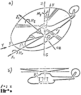 The distance x is the horizontal eg location and the distance у is the vertical eg location.
If the center of gravity is located ahead of the hub axis the eg is termed forward and denoted by +x.
If the center of gravity is located behind the hub axis it is termed aft and denoted by – x. Every helicopter has strictly defined eg travel limits. The forward eg limit is considerably greater than the aft limit.
For example, for the Mi-1 the
forward eg limit is +x. . = 150 mm,
lim
 the aft limit is – x,. = -53 mm.
lim
 The helicopter eg location must be known prior to every flight. The eg location changes with variation of
helicopter loading. The locations where the heaviest cargo is to be located is indicated in the operating manual for every helicopter. This manual also defines the sequence for finding the eg location, which amounts to the following. The basic helicopter weight (weight at a definite loading) and the basic eg location must be known. These data are presented in the helicopter specifications. Moreover, the weights and locations of the cargo must be
known. The distance from the main rotor hub axis to the cargo is measured in meters. The total moment about the main rotor hub axis is calculated and the new helicopter weight is determined as the sum of the basic weight and the weights of all the cargo. The new eg location is found from the formula
XM
X – £0′ •
Example of eg calculation of Mi-1 using the data:
(1) basic helicopter weight 1930 kgf;
(2) basic eg location 123 mm;
(3) eg limits +150, -53;
(4) additional cargo on helicopter:
= 85 kgf (at distance – 1.2 m ahead of hub axis);
= 38 kgf (at distance = 1.4 m behind hub axis);
G^ = 105 kgf (at distance = 0.5 m ahead of hub axis);
(5) cargo G^ = 72 kgf removed, was located at distance = 0.6 m aft
of hub axis.
Solution. We find the moments of the basic weight and the weight of each cargo
Consequently, flight cannot be made with this eg location; the helicopter will be uncontrollable. Some of the cargo must be shifted aft.
Let us find how far the cargo G = 105 kgf must be moved aft to locate
° car
the eg at +150 mm.
Solution.
1. We find the moment required to shift the eg 34 mm
AM = G Ax = 2086-0.034 =70.9 kgf. new
2.
We find the distance which the cargo must be shifted
That state of the helicopter for which it travels in a straight line with constant velocity and does not rotate about its principal axes (about the center of gravity) is called equilibrium.
The equilibrium conditions follow from the definition. According to Newton’s first law, a body moves uniformly and rectilinearly if no external forces act on it. Therefore, it is necessary that the sum of the forces acting on the helicopter be equal to zero
ZF =0. eg
The second equilibrium characteristic (absence of rotation) will hold if the sum of the moments of the forces acting on the helicopter equals zero
EM =0. eg
Moments relative to the о – z transverse axis are termed longitudinal
(M ). Under the action of this moment the helicopter pitches up (nose rises) z
or pitches down (nose descends). The moments about the 0 – x^ longitudinal axis are termed transverse or rolling moments (M^). The moments about the 0 – y^ vertical axis are termed directional (M^). A general remark on the sign of the moments: a positive moment causes clockwise helicopter rotation
if we look along the direction of the axis.
Equilibrium of the helicopter exists in all the steady-state flight regimes. The steady-state flight conditions, which we examined previously, are the equilibrium conditions written in expanded form. It is true that these conditions were written in application to the velocity coordinate system. The velocity or wind coordinate system is a system fixed with the flight velocity vector. In this system the longitudinal axis is denoted by 0 – x and coincides in direction with the velocity vector (see Figure 94a). The angle between the axes 0 – x^ and 0 – x of the body and wind coordinate systems is equal to the main rotor angle of attack A. The angle between the longitudinal axis of the velocity coordinate system and the helicopter plane of symmetry is called the sideslip angle. If the flight velocity vector is in the plane of symmetry, the sideslip angle equals zero. In the absence of sideslip, the transverse axes of the body and velocity coordinate systems
coincide. The angle between the vertical axes 0 – y^ and 0 – у of the body and velocity coordinate system equals the angle of attack of the main rotor.
We take for example the conditions for horizontal helicopter flight
We see from these equalities that the sum of the forces acting on the helicopter along the vertical, longitudinal, and transverse axes of the velocity coordinate system equals zero.
Consequently, these three equalities express the first equilibrium
condition EF =0. The fourth horizontal flight condition (EM = 0) eg eg
expresses the second equilibrium characteristic, i. e., the absence of rotation about the center of gravity.


 (y).
(y).

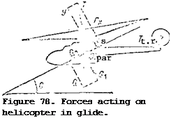 We resolve the main rotor thrust force into the lift force Y and the drag force P.
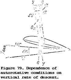 We first examine the influence on the autorotation conditions of the azimuthal variation of the resultant blade element velocity. Since the resultant velocity varies continuously in azimuth we cannot analyze this variation directly. Therefore, we take the two most characteristic azimuths, 90 and 270°, and we compare the autorotation conditions at these azimuths (Figure 80). The flight direction along the trajectory is shown in the figure by the arrow DF. The main rotor hub rotation plane is horizontal, the angle of attack of the main rotor lies
 The distance x is the horizontal eg location and the distance у is the vertical eg location.
 the aft limit is – x,. = -53 mm.


 par
par