Bending vibrations are those in which the blade chord displaces parallel to itself, i. e., there is not twisting of the blade. These vibrations occur when the line of blade section centers-of-gravity coincides with the elastic /184
axis. If the tip of such a blade is bent down, an elastic force P ^ appears, applied at the elastic center and directed upward (Figure 113). When the deflected blade is released, it begins to travel upward with an acceleration under the action of the elastic force. As a result of the acceleration there is formed the inertia force P^ , directed downward and applied at the center of gravity. We are examining a blade for which these points coincide; therefore the twisting moment of the inertia force will be zero, and there will be no twisting of the blade.
As the blade element moves upward, the elastic and inertia forces will decrease, while the bending motion velocity will increase. When the blade element reaches the neutral position, the elastic and inertia forces will be equal to zero while the velocity will be maximal. With further upward
movement of the blade, the elastic force changes its direction and will cause reduction of the velocity. The element motion stops in the extreme upper position. After passage through the line of equilibrium, the inertia force will be directed upward. This motion is shown in Figure 113, positions 1,
2. 3. The blade element will travel downward from position 3 (positions 3,
4, 5). The forces, acceleration, and velocity will vary just as in the upward motion. It follows from this analysis that the largest elastic forces and the largest accelerations of the bending motion will occur in the extreme positions. The inertia forces will be maximal for the largest accelerations, i. e., also in the extreme positions. If the blade section passes through the neutral position, the forces and acceleration change their signs and the velocity reaches its maximal magnitude. The variation of the velocity and!
acceleration is shown on the graphs of the vibratory motion. If the line of centers-of-gravity does not coincide with the elastic axis, the inertia force of the given blade element creates a torsional moment, which twists the blade relative to the elastic axis. The bending vibrations will be supplemented by torsional vibrations.
For most blades the line of centers-of-gravity lies behind the elastic axis. The nature of the bending-torsion vibrations of such a blade is shown in Figure 114. The direction and variation of the forces, velocity, and acceleration will be the same as for bending vibrations. As a result of the aft shift of the center of gravity relative to the elastic center, in the case of upward bending motion of the blade section there are created the additional positive twist angles (+ ф), which increase up to the neutral /185
position and then decrease (positions 1 – 5).
During downward bending motion of the blade, negative twist angles are created, which first increase in absolute magnitude and then decrease (positions 5 – 9).
This nature of the natural bending-torsion vibrations is determined by the mutual position of the elastic axis and the line of centers-of-gravity, and occurs for all blades.
|
|
|
Figure 114. Blade bending-torsion vibrations.
|
|
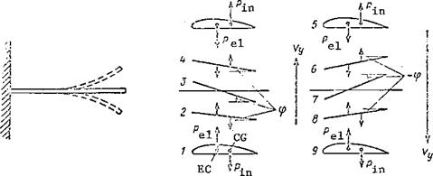
We have examined bending and bending-torsion vibrations of the blade in stationary air, i. e., when the rotor is not turning. If the rotor turns, the aerodynamic forces must be added to the elastic and inertia forces. The effect of these forces on the blade leads to flutter under certain conditions.
Essence of bending-torsion blade flutter. We imagine that bending – torsion vibrations of a blade take place while the main rotor turns. We resolve these vibrations along the blade line of motion with the air flow approaching at the velocity u (Figure 115). The elastic and inertia forces which arise during bending-torsion vibrations are not shown in Figure 115, but they do act. To these forces we add the additional lift force AY. As the blade flexes upward the twist angles will be positive, and this means that /186
there will be a positive increment (Да = ф) of the blade element angle of attack.
The additional lift force will be directed upward. When the flexing motion is downward, the twist angles will be negative, which means there will be a negative angle of attack increment (- Aa = – ф). The additional lift force will be directed downward. It follows from this analysis that the additional lift force coincides with the direction of the bending motion, i. e., it will be an exciting force.
|
м=о.
А а-9 = О

Act = (f-0 АУ=0
|
|
|

Acx = cPsO £4=0
|
|
Figure 115. Blade bending-torsion flutter.
Under the influence of the exciting force the bending vibration amplitude will increase, which leads to increase of the elastic forces, bending vibration accelerations, inertia forces, and their torsional moment. The twist angles and the additional lift forces increase. The conclusion is that bending vibrations cause twisting of the blade. Increase of the twist leads to increase of the bending vibrations, which in turn leads to increase of the torsional vibrations.
As a result the amplitude of the vibrations increases so rapidly that blade failure may occur.
Flutter occurrence conditions. Both exciting forces and damping forces arise in the case of bending-torsion vibrations. Flutter will be possible only if the exciting forces are larger than the damping forces. We have already shown that the exciting forces arise as a result of torsional vibrations, which lead to increase of the angle of attack.
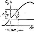
The lift force
27k
We see from the figure that the increment ДС
 У
У
depends on the angle of
attack increment Да and on
the slope of the curve to
the abscissa axis, which can
ДС
be defined as frr 3 — . 1 – v
Да ~a’
Hence
Thus, the exciting forces are proportional to the twist angle and the square of the blade tip circumferential velocity.
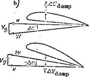
The damping forces arise as a result of the bending vibrations. During these vibrations there is a change of the blade element angle of attack as a result of the vertical velocity V of the bending motions (Figure 116b).
In the case of downward bending motion, the angle of attack increment is positive and the additional lift force is directed upward. In the case of downward bending motion, Да is negative and the additional lift force is directed downward. Thus, in all cases of bending motion the additional lift force is directed opposite this motion, i. e., it is a damping force
The lift force coefficient increase is proportional to the angle of aLtack, і. e. , ДСу — СЛя.


The conclusion is that the damping force is proportional to the velocity of the bending motion and the blade tip circumferential velocity. This is shown graphically in Figure 117, from which we see that the damping forces equal the exciting forces at a definite circumferential velocity. This velocity is called the critical flutter speed. Since u = 2irRns, the critical speed corresponds to the critical flutter rpm.
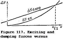 At speeds below the critical flutter speed (for rpm below the critical value) the damping forces are larger than the exciting forces, the bending-torsion oscillations will be damped, and flutter is not possible. At rpm above the critical value the damping forces are smaller than the exciting forces. The bending-torsion
vibrations will be increasing and flutter is inevitable. Consequently, flutter develops if the blade section eg line is behind the elastic axis and the main rotor rpm is above the critical flutter rpm. The first of these conditions holds for all blades; therefore the second condition is sufficient for the onset of flutter.
Dependence of critical flutter rpm on various conditions. The critical flutter rpm depends on the blade stiffness, mutual positioning of the eg line and the elastic axis, mutual positioning of the center-of-pressure line
and the elastic axis. The higher the blade stiffness in bending and torsion, the larger the exciting forces must be in order to deform the blade.
High velocity is necessary in order to obtain large forces. This means that the critical flutter rpm increases with increase of the stiffness.
Flutter of a metal blade is possible at a considerably higher rpm than for a blade of composite construction of the same dimensions. This is one of the advantages of metal blades.
If the blade eg axis coincides with the elastic axis, the natural vibrations will be flexural; without the torsional vibrations there will not be any exciting forces, and flutter will not occur.
If the eg axis is ahead of the elastic axis, the natural vibrations will be the bending-torsion type. However, the signs of the twist angles will be opposite to those for which flutter occurs, i. e., when the blade flexes upward the twist angles will be negative, and when the blade bends down the angles will be positive. With these vibrations associated with twisting, additional damping forces are created and flutter is impossible.
If the eg axis is behind the elastic axis, then the larger the distance between these axes, the larger the twisting moment of the inertia forces, and the lower the critical flutter rpm. This means that the blade eg axis must be moved forward in order to increase the critical rpm. To this end special weights in the form of metal bars, mass balance weights, are installed in the leading edge of the blade.
The mutual influence of the center-of-pressure axis and the elastic axis amounts to the fact that if the center-of-pressure axis is ahead of the elastic axis, an additional twisting moment on the blade is created from the action of the aerodynamic forces. The sign of this moment is the same as the sign of the inertia force moment. Consequently, in this case the critical flutter rpm will decrease.
Flutter characteristics of blade with hinged support. The majority of main rotors have blades with hinged support. The presence of the horizontal and axial hinges leads to the so-called flapping flutter, i. e., a combination of flapping motions with oscillations of the blade relative to the axial /189
hinge. The amplitude of such oscillations will increase. These oscillations are possible even for an absolutely rigid blade, in the absence of bending and twist.
During the flapping motions there is an increase of the amplitude of the vertical displacements of the blade element. The amplitude is made up of the flapping and bending displacements. In this case the critical flutter rpm decreases. Consequently, the hub horizontal hinges contribute to the onset of flutter.
The axial hinges permit the blade to rotate about its longitudinal axis.
This is equivalent to reduction of the blade torsional stiffness. Rotation about the axial hinge is possible as a result of elastic deformation of the blade pitch control linkage elements. The lower the stiffness of these elements, the lower the critical flutter rpm. The hub axial hinges also promote the onset of flutter.
The flapping compensator causes reduction of blade pitch as they flap upward, and increase of the pitch as they flap downward. This pitch change is analogous to the bending-torsion oscillations during flutter. Consequently, the flapping compensator also promotes the onset of flutter. The larger the compensation coefficient, the lower the critical flutter rpm. For most hubs the compensation coefficient К = 0.5. In the case of a large value of this coefficient, the critical flutter coefficient decreases to rpm values within the operational range.
The critical flutter rpm depends on the flight speed: with increase of
the speed there is an increase of the resultant velocity of the flow over the blade at the 90° azimuth, and this promotes the onset of flutter. This means that the critical flutter rpm decreases with increase of the flight speed.
278
In addition to the factors listed above, blade flutter is affected by centrifugal forces. As a result of the centrifugal forces the flapping motions and bending of the blade are reduced, and the blade becomes effectively stiffer. Consequently, the critical flutter rpm increases under the influence of the centrifugal forces.
In view of the lower blade stiffness, flutter of the main rotor blades does not develop as violently as does the flutter of the airplane wing, and therefore rotor blade flutter can be detected in time and measures can be taken to stop the flutter.
Operational sources of flutter. Flutter is avoided in the design of airplanes and helicopters. This means that in calculating the critical flutter rpm the blade stiffness and eg location are selected so that the critical flutter rpm is made considerably higher than the maximal permissible main rotor rpm. However, flutter can arise from operational causes, as a result of mass unbalance and reduction of the structural stiffness. Disruption of /190 the mass balance is particularly characteristic for blades of composite skeleton construction. In these blades the wooden ribs absorb moisture from the air markedly. With increase of the moisture content, the eg line shifts aft, which leads to reduction of the critical flutter rpm, and flutter becomes possible at operational rpm.
The mass balance may be disrupted as a result of careless overhaul of the blade, which also leads to the onset of flutter^ Reduction of the structural stiffness, which leads to reduction of the critical flutter rpm, occurs if there is a failure of the individual structural elements or in case of damage to the blade skin.
Under operational conditions flutter may occur with the main rotor operating on the ground and in flight. Flutter is detected by heavy vibration of the helicopter and from "blurring" of the main rotor cone of rotation. If there are no blade vibrations, the blades of a properly adjusted rotor will
travel along a single track and will form a definite cone, which is visible from the cockpit* If vibrations are present, the blades travel along different trajectories and the cone will be "blurred," vague.
When flutter is detected, the main rotor rpm must be immediately reduced to the minimal permissible value. After landing the reason for the flutter must be investigated. It must be kept in mind that "blurring" of the cone occurs not only in the case of flutter, but also if the blades are not in track, i. e., in case of improper adjustment of the main rotor. However, in the latter case the "blurring" is independent of the rpm.
Measures to prevent vibrations of all types. During helicopter operation, special attention is devoted to preventing all forms of vibration. These measures concern, first of all, strict adherence to all the operating conditions and performance of all the instructions and scheduled maintenance procedures for the particular helicopter type. These operations include the adjustment and alignment of all parts of the helicopter, verifying the proper adjustment of the vertical hinge dampers, proper charging of the landing gear shock absorbers and tires, verifying main rotor tracking, and checking the main rotor for flutter.
The essence of the flutter check amounts to the following: a definite
weight is attached to the trailing edge of each blade and the main rotor rpm is increased (helicopter parked) to the rpm indicated in the instructions.
Then the rpm is increased J>y 1 – 2%,and the rotor is operated in this condition for 1-2 minutes. Then the rpm is again increased and brought up to the maximal value indicated in the instructions. If flutter does not occur with the weights installed, there will be just that much more margin with the weights removed, since the critical flutter rpm increases as the blade eg moves forward.
[1] Motion power, i. e., the work expended per unit time in displacing
the helicopter, N = PV.
mot
[2] Induced power, i. e., the work expended per unit time in obtaining the lift force equal to the helicopter weight
(27)
[3] Power required for overcoming the main rotor blade profile drag
[4] V
gl sin 0 + fl
u – V, cos 0 gl
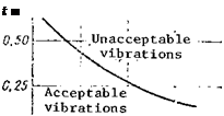
 Self-excited vibrations are those which arise under certain conditions
![]()


 V, = у? =




 Ф
Ф


 У
У
 At speeds below the critical flutter speed (for rpm below the critical value) the damping forces are larger than the exciting forces, the bending-torsion oscillations will be damped, and flutter is not possible. At rpm above the critical value the damping forces are smaller than the exciting forces. The bending-torsion