Category Helicopter Test and Evaluation

Fuselage contribution to Nv

The body lift and drag forces produced by the fuselage of a helicopter during sideslip will result in a net sideforce. This sideforce will produce a yawing moment which will be stabilizing or destabilizing depending on the relative positions of the force and the CG of the aircraft. In forward flight with no sideslip, a symmetrical fuselage would produce no net sideforce. However, in the same manner as the fin, the fuselage in a sideslip presents an angle of attack to the relative airflow equal to the sideslip angle. Fuselage lift and drag forces will then be produced (although the lift will usually be very small) parallel with and perpendicular to the relative airflow. Components of
these forces will give rise to the net sideforce, Yfus, which will in turn produce a yawing moment, Nfus. The point of action of the force in relation to the CG will determine whether or not this moment is stabilizing. The moment is given by:

Nfus = Yfus lfus = [1p(U2 + V2 )Sfus CD sin P]lfus

Note that the component of the fuselage lift force has been neglected. The magnitude of the fuselage contribution to Nv for a given fuselage shape will increase with increasing forward speed, sideslip velocity and fuselage drag area.

Подпись: 4.10.1.4Подпись:Подпись: 4.10.2.1Подпись: 4.10.2.2Main rotor contribution to Nv

As the helicopter sideslips, the main rotor will flap away from the direction of the airflow as has been described above (a1 and bx effects). The tilting of the thrust vector will produce a horizontal thrust component that manifests itself as a sideforce at the rotor hub. If the main rotor is tilted forward with respect to the z-axis of the helicopter then a yawing moment will be generated. This moment will provide a destabilizing contribution to Nv but it will be small in relation to the others.

Fin contribution to Nv

In forward flight with no sideslip or rotor wake interference a symmetrical fin produces no net sideforce. However, should the helicopter sideslip to the right, say, the relative airflow is such that the fin now has an effective angle of attack equal to the sideslip angle. The net sideforce, YF, produced by the fin comprises components of both the fin lift, Lf , and drag DF. This force will give rise to a yawing moment, NF, given by:

Nf = Yf lF

where lF is the moment arm. If the fin lift and drag coefficients and the effective fin area, SF, are known, then:

Nf = [2(U2 + v2)pSF (CL cos p + CD sin p)]lF

The direction of this moment is such that it will always tend to yaw the helicopter into the direction of the sideslip, thus it is stabilizing. The size of the moment for a given fin design will depend on the forward speed, Ue, and lateral velocity, v.

Directional (yawing) static stability

Contributions to the directional stability of a helicopter arise from the tail rotor, the fin, the fuselage and the main rotor. Suppose the helicopter was in a sideslip to starboard, then for positive static stability there must be a yawing moment also to starboard which tends to align the aircraft with the relative wind direction. The change of yawing moment, N, due to sideslip velocity, v, is the derivative Nv, so for static stability, this must have a positive value.

4.10.1.1 Tail rotor contribution to Nv

The tail rotor always provides a stabilizing contribution to Nv, which arises from the change in tail rotor thrust with change in sideslip velocity. In steady forward flight, the thrust produced depends on the blade angle of attack. Consider a blade element at radius, r, from the tail rotor hub. In forward flight at speed Ue, the blade element experiences a velocity in the plane of rotation of Ue + )trr (where )tr, is the tail rotor rotational speed) and a velocity perpendicular to the plane of rotation, vtr, due to inflow. Now the angle of attack of the blade element is given by:

a = 9tr — ф

Подпись: ф = tan 1 Подпись: vtr Ue + ^tr r

where 9tr is the tail rotor collective pitch angle and ф is the inflow angle given, on the advancing side, by:

In positive side-slipping flight with sideslip velocity v, the relative air flow direction now makes an angle p with the plane of rotation, given by p = tan~i (v/Ue). The inflow through the tail rotor is now increased by the value of the sideslip velocity and the inflow angle is now given by:

Подпись: nr + v Ue + ^tr r
Подпись: ф5 = tan 1

This changes the blade element angle of attack to:

as = 0tr — ф5

The angle of attack has therefore been reduced by the sideslip (assuming tail rotor collective remains constant) which in this case will result in a reduction in tail rotor thrust, *Ttr. Now the fuselage torque reaction, 2MR, is initially balanced by the tail rotor thrust moment. So:

2mr = Ttr ltr

where Ttr = tail rotor thrust and ltr = tail rotor moment arm. The reduction in tail rotor thrust caused by the positive sideslip means that this balance is no longer maintained (assuming no rapid change in main rotor torque) and an out-of-balance yawing moment Ntr, is produced that is given by:

Ntr = 2mr — (Ttr — *Ttr )ltr = *Ttr ltr

This yawing moment will cause the helicopter to yaw to starboard into the direction of the sideslip. Hence, the tail rotor contribution to Nv is positive and therefore stabilizing. This applies to both tractor and pusher tail rotors.

LATERAL/DIRECTIONAL STATIC STABILITY

When addressing the question of lateral and directional stability it is convenient to assume that the motion can be analyzed separately from the longitudinal motion.

Cross-coupling terms are therefore ignored to obtain a reasonable feel for the subject but it must be remembered that in the real case cross-coupling will occur and these effects will almost certainly modify the results obtained. Here only the lateral/ directional static stability of the helicopter shall be considered which is dominated by the derivatives Lv, Lp, Nv, and N. Major contributions to these derivatives come from the main rotor, the tail rotor, the fin and the fuselage. The control displacements, required to maintain steady side-slipping flight at constant heading which are related to the corresponding static stabilities, are also described. The lateral cyclic displacement is related to the lateral (rolling) static stability, (Lv) and the yaw pedal displacement is related to the directional (yawing) static stability, (Nv). In order that the control movements should be in the conventional sense it is necessary that both Lv and Nv are stabilizing. It is worth remembering the sign convention for control deflections; positive control displacement produces negative aircraft response (lateral cyclic stick movements to the left and left push of the yaw pedals are taken as positive).

Effect of change in speed stability

In a similar manner the effect of a change in the speed stability can be demonstrated by a change to the value of the pitching moment due to speed (Mu). In order to isolate this effect it is necessary to eliminate the influence that the pitching moment due to vertical speed (Mw) may have on the ensuing long-term dynamics. This is achieved by setting Mw to zero. Consider the following three cases:

(1) Standard speed stability (Mw = 0)

£ = — 0.0769, mn = 0.324 rad/s, T1 = 1.06 s, T2 = 0.38 s

(2) Half standard speed stability

" — 0.0460

0.0385

2.7192

— 9.8052

A120 =

0.0221

— 0.9008

61.5403

0.3205

0.0150

0

— 2.6060

0

0

0

0.9989

0

£ = — 0.0115, mn = 0.233 rad/s, T1 = 1.08 s, T2 = 0.37 s

(3) Twice standard speed stability

" — 0.0460

0.0385

2.7192

— 9.8052

A120 =

0.0221

— 0.9008

61.5403

0.3205

0.0600

0

— 2.6060

0

0

0

0.9989

0

£ = — 0.1440, mn = 0.449 rad/s, T1 = 1.04 s, T2 = 0.37 s

The effect of Mu can now be seen clearly. Only the long-term mode is affected significantly and it is evident that stronger speed stability causes a more divergent, and higher frequency, long-term response. The moment arising from flying at an off-trim speed is greater if the speed stability is stronger. This larger moment causes the helicopter to return towards trim more aggressively thereby producing a more divergent response.

Effect of aero-derivatives on dynamic stability modes

The dynamic response of a helicopter is governed by the values of the aerodynamic and control derivatives that make up the characteristic equation and stability matrices. Most of the important derivatives are speed dependent so it will be instructive to examine the variation in the dynamic modes with airspeed as well as determining the effect of modifying single derivative values.

4.9.7.1 Effect of airspeed

Some idea of the likely behaviour can be obtained by examining the aero-derivative and control matrices. Below are a set of matrices for three flight cases: hover, 60 KTAS and 120 KTAS.

– 0.0253

0.0215

0.6675

– 9.7838

0.0276

– 0.3120

0.0135

– 0.7215

0.0482

0.0051

– 1.8955

0

0

0

0.9986

0

6.9418

– 9.2861

– 93.9176

– 0.0021

0.9554

26.4011

0

0

– 0.0243

0.0392

– 0.6705

– 9.8014

– 0.0467

– 0.7285

30.8626

– 0.4200

0.0280

0.0248

– 2.2189

0

0

0

0.9995

0

Ahov

Bh0v —

A60 —

4.6289

– 8.0560

– 107.3895

– 21.2286

10.7004

27.6889

0

0

– 0.0460

0.0385

2.7192

– 9.8052

0.0221

– 0.9008

61.5403

0.3205

0.0299

0.0380 –

2.6060

0

0

0

0.9989

0

3.8024

– 7.0223

B60 —

A120 —

Подпись: BПодпись:– 135.2501 – 49.3052

20.9344 30.9867

0 0

The dynamic stability of the helicopter can be assessed by studying the eigenvalues of the A matrix. The eigenvalues equate to the solutions of the differential equations that underpin the matrix itself. Recalling that a negative real part is indicative of a convergent response and that a pair of complex roots imply an oscillatory motion we are in a position to describe the dynamic modes:

(1) Hover. The eigenvalues of the Ahov are:

0.0548 + 0.4805г, 0.0548 – 0.4805г, – 0.3142, – 2.0282

These eigenvalues imply an unstable second-order dynamic mode and two stable first-order responses. The second-order mode has a natural frequency of 0.484 rad/s (period of 13.0 s) and a relative damping value of — 0.1133 (T2 of 12.6 s). The first-order responses have time constants of 3.18 s ( — 0.3142) and 0.49 s ( — 2.0282).

(2) 60 KIAS. The eigenvalues of the A60 matrix are:

0.0735 + 0.3822г, 0.0735 — 0.3822г, — 0.4725, — 2.6460

These eigenvalues imply an unstable second-order dynamic mode and two stable first-order responses. The second-order mode has a natural frequency of 0.389 rad/s (period of 16.2 s) and a relative damping value of — 0.1885 (T2 of 9.4s). The first-order responses have time constants of 2.12s ( — 0.4725) and 0.38 s ( — 2.6460).

(3) 120 KIAS. The eigenvalues of the A120 matrix are:

0.1995 + 0.3784г, 0.1995 — 0.3784г, — 0.4191, — 3.5326

These eigenvalues imply an unstable second-order dynamic mode and two stable first-order responses. The second-order mode has natural frequency of 0.428 rad/s (period of 14.7 s) and a relative damping value of — 0.4664 (T2 of 3.5 s). The first-order responses have time constants of 2.39s (—0.4191) and 0.28s ( — 3.5326).

The period of the oscillatory mode is fairly long and this would be called the long­term dynamic mode which characterizes the dynamic stability. Therefore this helicopter is dynamically unstable and the degree of instability increases with speed.

4.9.7.2 Effect of increased pitch damping

The effect of an increase in pitch damping, achieved by a direct increase in the value of the pitching moment due to pitch rate (Mq), can be easily shown by increasing the appropriate value in the A matrix. Suppose that the value of Mq is doubled from — 2.505 to — 5.212:

" — 0.0460

0.0385

2.7192

— 9.8052

0.0221

— 0.9008

61.5403

0.3205

0.0299

0.0380

— 5.2120

0

0

0

0.9989

0

Подпись: 7.0223 49.3052 30.9867 0 3.8024 —

— 135.2501 —

20.9344 0

The effect of this change on the dynamic response of the helicopter can be seen from the change in the eigenvalues:

(1) Before. 0.1995 + 0.3784г, 0.1995 — 0.3784г, — 0.4191 and — 3.5326, which result in the following engineering parameters:

£ =— 0.4664, mn = 0.428 rad/s, T1 = 2.39 and T2 = 0.28

(2) After. 0.0501 + 0.2916г, 0.0501 — 0.2916г, — 0.5411 and — 5.718, which result in the following:

£ =—0.1693, mn = 0.296 rad/s, T1 = 1.85 and T2 = 0.17

This suggests that increasing Mq will reduce the frequency of the long-term mode and shorten the time constant for the short-term mode (control response).

Short-term or pitch (subsidence) mode

Instead of the SPPO, there are usually two aperiodic motions, one with a short time constant and one with a longer time constant, the former being masked by the latter. Just as the dynamic stability of the helicopter is directly related to its long-term modes the control response is characterized by the short-term modes. Whenever a pilot makes a control input the helicopter is excited dynamically and if left to its own devices will exhibit all the modes discussed above. However when the pilot wishes to manoeuvre the aircraft he will only be concerned with the response in the short term and therefore the short-term dynamic modes along with the control derivatives can be used to predict the handling qualities of the helicopter. In the matrix equations this means that for pitch subsidence everything but the third row and column can be ignored, so the equations of motion presented earlier reduce to:

q = Mq. q + MBl Bl + Mec.0c

With no collective input this becomes: q = Mq. q + MBl. Bl

q MBl

B = (s – Mq)

which describes a classic first-order type of response. Thus the time constant of the pitch subsidence mode is dependent solely on the value of Mq, the pitch damping derivative.

Dynamic stability in the hover

Some of the derivatives can be assumed to approximate to zero in the hover case (Xw, Zu, Zq, Zw, and Mw) and the characteristic equation typically solves to give two real roots and a pair of complex roots. One real root can be shown to be (s — Zw) = 0, so that s = Zw. This represents a heavily damped subsidence such that if a helicopter is disturbed, by a vertical gust for example, the subsequent heave motion is quickly damped out. The motion is a pure convergence with no oscillation and confirms that the vertical motion is completely decoupled from the pitching and fore/aft motions, a prediction arising from examination of the Z-force equation in the hover. The other real root represents the forward speed mode. In the hover the pitching oscillation or falling leaf mode masks this mode.

The physical description of the motion associated with the complex root is handled easily. Assume that the hovering helicopter experiences a small horizontal velocity disturbance, the relative airspeed change causes the rotor to tilt backwards and exert a nose-up pitching moment on the helicopter. A nose-up attitude then develops and the rearward component of the thrust vector decelerates the aircraft until its forward motion is stopped. At this point the disturbing disk tilt and rotor moment vanish but the helicopter is left in a nose-up attitude and backward motion begins. This causes the rotor to flap forwards and exert a nose-down moment. The thrust vector tilts forward and the rearward motion is stopped but the helicopter is now left in a nose – down attitude which accelerates it forward and the cycle begins again. The motion is generally unstable and its amplitude increases steadily, bearing out the analytical solution. The instability is entirely due to the characteristic backward flapping of the rotor with forward speed. However, the pitch damping derivative Mq will affect the rate of divergence. Making Mq more negative will reduce the real part of the complex root and hence increase the time to double amplitude of the motion. It can never make the motion stable, however, and at best only neutral stability can be achieved.

Подпись: falling leaf frequency = m
image107

Bramwell [4.1], discusses the implications of positive Mu on the motion, that is the possibility of making the rotor flap forward with speed, but this only leads to a pure divergence which is even more undesirable. He also quotes the results of investigations into the effects of configuration changes on the dynamic stability of the hovering helicopter but it appears that no reasonable change will significantly improve it. In particular, CG position has little effect on the stability but simply affects the fuselage attitude adopted, even for blades with offset hinges or hingeless rotors. Although a hub moment can be exerted in these cases and it is therefore no longer necessary for the thrust vector to act through the CG, thrust changes due to forward speed and pitch rate are typically zero in the hover. The motion can be approximated to a neutral oscillation whose frequency depends on Mu and Mq:

4.9.3 Dynamic stability in forward flight

The characteristic equation in forward flight resolves into four roots but it is not so easy to generalize as in the case with a conventional fixed wing aircraft. For the latter,
the characteristic equation resolves into pairs of complex conjugate roots representing two oscillatory motions, one of short period and high damping – the SPPO – and the other of long period which is lightly damped – the phugoid. In the case of a helicopter the characteristic equation solves into four roots but for a particular helicopter two pairs of complex roots may be found at one flight condition, two real and a pair of complex roots at a second condition and four real roots at a third. The reason for this is the large variation in the value of the derivatives over the flight envelope. In the longitudinal case Mw has the greatest influence, with Mq, Mu and Zw also playing a part in the overall result. Although rotorcraft do not, strictly speaking, exhibit the SPPO and phugoid motions described for fixed wing aircraft, there are certain analogies which can be drawn.

The phugoid motion of a fixed wing aircraft is an oscillation involving changes in height and speed at approximately constant incidence. A disturbance producing, for example, an increase in lift causes the aircraft to climb slowly as lift now exceeds weight. The climb (which is at constant incidence) results in a decrease in speed and consequent loss of lift and eventually leads to a situation where lift and weight are again equal but the aircraft continues to slow down. A descent begins as weight exceeds lift and the consequent increase in speed produces an increase in lift and the climb starts again. The oscillatory motion experienced by a helicopter is influenced by the respective values of the speed stability, Mu, the angle of attack stability, Mw, the pitch damping, Mq and the pitching moment of inertia, Iyy.

Dynamic stability in the hover Dynamic stability in the hover

Consider the motion following a disturbance that causes the helicopter to adopt a nose-down attitude and start to descend. Initially, rotorcraft with neutral angle of attack stability (Mw = 0) will be considered. The component of aircraft weight acting along the flight path accelerates the helicopter but as speed increases the rotor disk flaps back (speed stability) and a consequent nose-up pitching moment and angular acceleration occurs. This soon produces an angular velocity such that the pitch damping causes the fuselage to rotate to a greater angle of attack than the rotor, and this effectively neutralizes the thrust vector tilt due to static stability. The flight path is still downwards, however, and the component of weight acting along it ensures that the airspeed continues to increase so that the preceding steps are repeated. The angular velocity continues to increase with consequent increase in fuselage angle of attack. In turn, the thrust continues to increase until it is sufficient to level off the glide path. At this point the helicopter has reached its maximum forward speed, maximum nose-up pitch rate, and maximum fuselage angle of attack. The thrust now exceeds the weight and the aircraft begins to climb. The component of weight acting along the flight path now starts to slow down the helicopter. The rotor disk flaps forward as the rearward tilt due to speed stability is exceeded by the forward tilt due to pitch damping. The nose-down damping moment reduces the pitch rate and the fuselage angle of attack until they reach their trim values. The helicopter is still climbing, however, so the speed continues to decrease and the rotor flaps forward. The resulting nose-down pitching moment starts a similar sequence of events (with opposite signs of course) and this will be repeated until the oscillation eventually either damps out (stable) or grows worse (unstable). It is possible to characterize the long-term mode as [4.1]:

The frequency of the long-term mode is therefore inversely proportional to the trim speed, Ue. An increase in trim speed thus reduces the frequency resulting in a larger period for the oscillation. An increase in Zu (related to the lift coefficient), on the other hand, has the opposite effect. The damping of the long-term mode is affected by the same factors, but in the opposite sense, so an increase in trim speed will increase the damping in addition to reducing the frequency of the response. The drag of the helicop­ter (related to Xu) also affects the ‘phugoid’ frequency. A helicopter carrying large external stores (higher drag coefficient) is therefore likely to exhibit a more heavily damped long-term response. A less simplified relationship for £ shows that the pitch damping, Mq, adds to the damping of the long-term mode whereas Mu reduces it [4.3].

Longitudinal motion of the helicopter

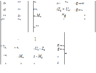
To analyze the longitudinal dynamic stability characteristics of the helicopter it is necessary to consider the equations governing its motion. In order to study these equations, simplifying assumptions are required to ease the computational task. The matrices describing the equations of motion often include several acceleration depend­ent derivatives such as M„-. Assuming all these are negligible and the centre of gravity is aligned with the main rotor drive shaft such that dx = dy = dz = 0, then:

control theory when applied to multi-input/multi-output (MIMO) systems states that the Characteristic Equation (CE) can be obtained from the following:

det(sI — A) = 0

where A is the result of pre-multiplying Ma by M. The CE when solved will show the nature of the controls fixed response of the helicopter to a disturbance. So:

Подпись:Подпись:Подпись: Therefore:Подпись: CE == 0

This determinant will be of the form, As4 + Bs3 + Cs2 + Ds + E = 0, where the coeffi­cients in the polynomial can be expressed in terms of aerodynamic derivatives, see Bramwell [4.1]. The quartic may be solved by numerical computer methods when the values of the coefficients are known. Consequently the characteristic equation can be evaluated and factorized. For helicopters, in most cases, the equation factorizes to:

(T s + 1)(T2 s + 1)(s2 + 2^mn s + m2) = 0

The three modes of motion implied by this equation are summarized below:

(1) Vertical velocity mode. The vertical velocity mode, described by (Tts + 1) = 0 is a stable, heavily damped subsidence in vertical velocity. The motion is decoupled from speed and pitch and has a time constant of the order of 1 to 2 seconds.

(2) Forward speed mode. The forward speed mode, described by (T2s + 1) = 0 is a stable, heavily damped subsidence in speed. The motion is coupled with pitch attitude and pitch rate. It has a short time constant of the order of 0.5 second.

(3) Pitching oscillation. The stability of the pitching oscillation is both speed and flight condition dependent. In the climb or at high speed the oscillation can be unstable, possibly degenerating to an exponential divergence at high speed. The oscillation couples with the forward speed mode and is mainly due to rotor flapping caused by speed changes.

These basic equations of motion govern the aircraft in all flight regimes but differing values of the derivatives account for differences in the behaviour and will, of course, give different characteristic equations to solve. It should be remembered that all modes will be excited following a disturbance or pilot input. The various dynamic modes described above can be separated into long-term modes and short-term modes. The long-term modes characterize the dynamic stability of the helicopter, whereas the short-term modes affect the pilot’s perception of the aircraft during manoeuvres, that is its control response.

Collective pitch derivatives

When the collective pitch, 0c, is increased, each blade experiences an increase in lift and the total rotor thrust is increased. The pitch increase also leads to an increase in flapback of the disk in forward flight and a subsequent nose-up pitching moment. This helps to explain the derivatives:

(1) Forward force due to collective (X0c). The forward force due to collective is usually negligibly small.

(2) Vertical force due to collective (Z0c). An increase in collective always produces
an increase in thrust ( — ve Z) so is always negative. It is known as the collective control power derivative, or the heave control power.

(3) Pitching moment due to collective (M0c). As outlined above, the increased flapback and thrust combine to produce a nose-up pitching moment in forward flight so the derivative is positive. As the disk does not flapback in the hover, M0c is zero in this flight regime, provided the horizontal stabilizer is unloaded and the tail rotor is conventional (not canted).

4.9.2.1 Cyclic pitch derivatives

Remembering that only fore/aft cyclic are being considered, any such pitch change will result in a change in the disk tilt, also fore/aft, and of the thrust vector. Hence, a pitching moment will be generated, nose-down for forward stick deflection and nose – up for rearward stick. The corresponding cyclic derivatives are:

(1) Forward force due to longitudinal cyclic (XBl). The forward force due to longi­tudinal cyclic is usually negligible.

(2) Vertical force due to longitudinal cyclic (ZBl). The vertical force due to longi­tudinal cyclic is negligible.

(3) Pitching moment due to longitudinal cyclic (MBl). Pitching moments are generated as described above, and MBl is known as the pitch control power derivative, or the ‘longitudinal cyclic control power’.