Category Helicopter Test and Evaluation

Safety of operation of autopilot

As the autopilot is controlling the flight path of the aircraft there are a number of safety issues that are addressed in the test programme. For three-axis autopilots which control vertical modes through the cyclic pitch channel there is a potential problem if the pilot does not apply sufficient collective pitch to maintain airspeed, particularly when climbing in a vertical speed mode. In this case airspeed may fall below the minimum power speed resulting in a higher pitch attitude and a further fall in airspeed. This in turn may lead to the operational pilot becoming disorientated. For these types of systems there should be an airspeed cutout or, at minimum, a warning to the crew that airspeed is decreasing. For systems that control the vertical modes or altitude holds through the collective channel the possibility of the system making demands that result in an exceedence of a power limit is investigated. For example, above a certain airspeed or rate of airspeed increase a height hold may cause an excessive torque demand. In this case the testing may result in limitations being imposed on the maximum airspeed or the rate of airspeed change that is permitted with the hold engaged.

7.3 FAILURE TESTING

While the majority of testing involves the assessment of an aircraft with all its systems serviceable, a smaller but important portion involves evaluating the effect of system failures. The most important failures are those that affect the flight path of the aircraft and for these the test methodology employed always remains the same.

The initial stage of failure testing is to study and fully understand the system under evaluation. This is not simply a question of understanding what the individual parts of a system do but also understanding the way in which the system is used in the role. It is only with a detailed knowledge of the operational use of the aircraft that the implications of failures can be fully realized. As with all testing the incremental approach is fundamental when assessing failures. This is particularly important in the

case of critical components such as the flight control system and powerplants where a failure can take an aircraft rapidly from a safe flight condition to a potentially hazardous one. Even failure testing of aircraft systems that are considered non-critical should be approached incrementally as unexpected results may follow. The golden rule for failure testing, particularly of critical systems, is only vary one parameter at a time. For example, when evaluating the height/velocity diagram of a helicopter the height at the moment of failure should be kept constant and the airspeed varied or vice versa. To vary two or more parameters simultaneously makes it difficult to predict the outcome and to determine trends. There is also a greater risk of unexpectedly meeting a ‘cliff edge’ change in failure characteristics if multiple parameters are varied simultaneously. The identification of trends through the analysis of results is an essential part of the approach to critical system failure testing.

Autopilot performance

Testing the performance of the autopilot typically involves engaging each mode and assessing how accurately it is able to carry out its function. As autopilots rely on external signals for many functions such as VOR tracking or automatic ILS approaches, this type of testing has to be conducted within an assessment of the accuracy of the signals received. Only when it has been established that the external signals are being received accurately can the ability of the autopilot to manoeuvre the aircraft in response to these signals be evaluated. Testing of the autopilot is conducted initially in ideal conditions of low turbulence to establish the baseline performance and finally in operationally representative conditions such as high turbulence and large crosswinds.

Although there are too many autopilot modes to discuss in detail the tests used for the most common functions are detailed below:

• Altitude holds. These are tested by engaging the hold and measuring the accuracy with which it maintains the datum in still and turbulent conditions. As an example a recent UK military helicopter specification called for the barometric height hold to maintain the aircraft within 25 feet of the engagement height. Deliberate use of controls in the other axes is also made to determine if the hold is able to cope with the off-axis interference (for example, the angle of bank is increased, airspeed changes are made, or with a three-axis system which maintains altitude through the pitch channel, power changes are made). Large disturbances can cause the series actuators to saturate and the slower-acting parallel actuators may be unable to respond with sufficient speed thereby causing a large disturbance from the datum. Such testing may lead to restrictions being placed on the flight envelope with the hold engaged. The actuator activity is always examined closely to ensure that saturation has not occurred. For 3-channel systems that also employ trim follow-up the cyclic activity demanded to maintain the series actuators within authority is an important issue. The capture of the hold datum is also explored by, for example, engaging the hold with a rate of climb or descent. The ease with which the hold datum can be changed is also examined; for example, it should not be necessary to completely disengage the hold and then re-engage it when at a new altitude. [16] vertical speed and its behaviour when the direction of the commanded speed is reversed are also investigated. In addition the ease of changing from the vertical speed mode to an altitude hold mode is assessed.

• Airspeed holds. Testing of an airspeed hold is approached in the same way as a height hold by noting the deviations from the datum in still and turbulent conditions. Power changes are also made to check the hold accuracy as the power is changed and when steady in climbs or descents. As some autopilot systems provide airspeed hold but rely on the pilot to select the datum speed the accuracy and workload associated with selecting a new airspeed can be of great interest. In addition the effect of pressure errors on the system are investigated by inducing deliberate sideslip.

• Turn co-ordination. The effectiveness of turn co-ordination features is tested by conducting turns at various rates without use of the yaw inceptor. Manoeuvres such as roll reversals are also used. A particular area of interest is the manner in which the turn co-ordination is mechanized and integrated with the heading hold. On some systems turn co-ordination will disengage and the heading hold will engage below set yaw rates, bank angles, or airspeeds. For example, in forward flight the SFIM 85T31 autopilot fitted to the AS 355 changes from heading hold to turn co-ordination as the angle of bank exceeds 5°. The heading hold will then automatically re-engage on completion of a turn as the heading rate falls below 1.5 degrees per second. The Boeing Chinook system on the other hand uses lateral cyclic displacement from trim to engage turn co-ordination. Clearly the implica­tions of this automatic changeover requires investigation in a variety of flight condi­tions and role manoeuvres. This is particularly important if the logic changes above a certain airspeed to account for the need to turn the helicopter in forward flight as opposed to performing a lateral sidestep in the low speed regime.

• Navigation modes. Autopilots can offer a number of navigation features. In each case the testing examines the accuracy with which the autopilot can track the navigation feature being used as well as the performance of the system when capturing the datum. For example, a VOR mode is tested by intercepting the required radial at a variety of intercept angles and airspeeds. The feedback gain should be high enough to correct errors in tracking but not so high that it leads to uncomfortable and frequent roll inputs; this becomes particularly important as the aircraft approaches the navigational aid or waypoint. This type of assess­ment may highlight problems in the relationship between the roll and yaw channels in turning the aircraft and maintaining the heading. The action of the autopilot at turning points is often an area of great interest as the system logic has to decide when to start the turn onto the next leg and then has to capture this new track. A consideration is the matching of the demands of the autopilot with the capabilities of the aircraft. It should not be possible to programme a search pattern which the aircraft is physically incapable of following.

• Automatic ILS approach mode. Testing of this mode is conducted in a variety of wind strengths and directions to assess how well the localizer and glideslope indications are maintained. The full range of permitted airspeeds is also used. As with navigation mode testing the capture of the localizer is assessed at different approach angles. Three-axis systems are sensitive sometimes to power variations during the approach therefore collective inputs are made once established on the localizer and glideslope and tracking accuracy is noted.

• Automatic transitions. A common feature on naval and SAR helicopters are automatic transitions to and from the hover. As this autopilot mode operates close to the surface, often in conditions of degraded visual cues, it is particularly important to test it thoroughly. Because these autopilot modes are required to control the aircraft from one extreme of speed to the other and climb and descend the aircraft, they are usually given considerable authority to be able to perform their task. Tests are conducted at a variety of weights, sea states, centres of gravity, wind speeds, turbulence levels and entry conditions. If automatic series actuator trim is not provided tests are made with different initial actuator positions to determine at what point saturation occurs. Considerations also include the ease of deselecting parts of the system, the monitoring requirement on the crew, and the safety of the flight path of the aircraft. The actions that the pilot would have to take in the event of an engine failure during a transition are an important part of the assessment.

Lateral and directional static stability

The complex inter-relationship between the roll and yaw channels of a typical ASE make conventional lateral and directional static stability testing both difficult and unwarranted. It might actually be impossible to perform a steady-heading sideslip without over-riding part of the ASE system. For example, if lateral cyclic immediately initiates a turn the pilot will have to apply yaw pedal to hold a given sideslip angle thereby effectively disabling the yaw channel of the ASE and negating the test. For unaugmented helicopters measurement of LV and NV help to quantify the aircraft’s tendency towards spiral instability, its natural turn co-ordination characteristics and its propensity to oscillate laterally and directionally. All these qualities are heavily affected by the ASE further negating any assessment of static stability. For helicopters without bank angle initiation of turn co-ordination, turn-on-one-control tests may still be appropriate as methods of assessing the performance of the heading hold and roll attitude hold.

7.5.2.5 Spiral stability

As with manoeuvre stability the actual spiral stability characteristics of a helicopter may be completely suppressed when the ASE is engaged. The amount of in-turn stick required during a level turn can no longer be used as an indication of the helicopter’s natural spiral stability since the lateral cyclic deflection from trim may be derived purely from the requirements of the ASE system. Some systems are engineered to display neutral stability with the stick returning to the centre once a turn has been initiated. Alternatively other systems show the characteristics of strong stability, with the angle of bank and rate of turn being directly proportional to the amount of in­turn stick.

7.5.2 Autopilot testing

There are three main aspects to testing autopilots: the interface with the pilot, the performance of the system, and the safety of operation.

7.5.3.1 Pilotlautopilot interface

As the autopilot is directly controlling the flight path of the aircraft it is extremely important that the pilot is fully aware of which modes are engaged and what those modes are directing the aircraft to do. The assessment of the interface examines the display of autopilot status, the method of mode selection/deselection, and the requirement on the crew to monitor the system operation. A particularly important issue is the warning provided to the pilot that a function has been deselected or has failed. The pilot must be able to assimilate with ease which aspects of the flight path are no longer under automatic control. Of equal importance is the ease with which the pilot can ‘fly through’ an autopilot mode if he or she elects to fly the aircraft manually rather than disengage the mode. This situation usually arises when there is a sudden requirement to manoeuvre the aircraft.

Longitudinal static stability

Since the purpose of the pitch channel of an ASE is to maintain pitch attitude for long periods it should in theory have no effect on longitudinal static stability (LSS) data. If, however, the ASE features trim follow-up and the aircraft is significantly unstable, requiring continuous trim movement to maintain series actuator authority, it may be difficult to quantify CFSS using the conventional test. The validity of CFSS testing must therefore be considered. In normal operations the pilot will wish to select a given airspeed and maintain it with minimum workload. The quality of airspeed maintenance afforded by a typical ASE will depend on the tightness of its attitude hold (this can be assessed during ‘long-term testing’) and the variation of trimmed attitude with airspeed, which can be documented during a conventional trimmed flight control position (TFCP) test. Handling problems may arise during airspeed selection if, for example, movement of the stick to generate a new attitude causes the trim follow-up to activate, which in turn leads to oscillations in airspeed. Thus, precise selection of a given airspeed may be very difficult requiring inordinate pilot workload to match stick position and aircraft attitude with the desired ASI reading. A valid test of airspeed maintenance, provided the ASE does not feature trim follow-up and the cyclic has absolute centring, is the conventional release to trim test. It should be remembered that during this test the pilot is generating a pulse disturbance in attitude rather than airspeed. The ASE should quickly re-acquire the datum attitude, however, the helicopter may regain the original airspeed only very slowly, with many overshoots, or not at all.

7.5.2.3 Cross-coupling

Open loop changes in power should not cause any pitch/roll/yaw coupling if the attitude hold is sufficiently tight. Indeed this test can be used to assess attitude hold performance. The magnitude of the underlying cross-coupling can be gauged by observing series actuator activity. Large changes in power may cause the cyclic to move longitudinally through the action of the trim follow-up system.

7.5.2.4 Manoeuvre stability

Assessing the manoeuvre stability characteristics of an ASE equipped aircraft is difficult and less important than discerning the ease with which the pilot can turn the aircraft. If the role requires aggressive altitude changes (NOE flight) a qualitative assessment of the handling qualities during pull-up and pushover role manoeuvres, such as wire avoidance, should be considered. Formal academic PUPOs cannot be conducted, however, due to the suppression of pitch rates by the ASE. Thus, although level turns and PUPOs may be assessed qualitatively with ASE engaged the resulting cockpit control positions and activity should not be taken as indicative of the underlying characteristics of the helicopter.

Consider performing a level turn with altitude hold engaged and assume that turn co-ordination is active. The pilot will initiate the turn with lateral cyclic by selecting an appropriate bank angle. Since the thrust vector is no longer vertical more collective pitch will be required to maintain level flight and the lever will automatically trim upwards possibly generating a pitching moment. Any tendency to slip or skid in the turn will be eliminated by the yaw channel of the ASE. Movement of the cyclic stick in the longitudinal sense during the turn is dependent on many factors not least of which is the AFCS designer’s perception of the most suitable stick cues for this phase of flight. The tendency of the helicopter to ‘dig-in’ in steep turns should be completely suppressed by the fast-acting series actuators so that no residual movement is seen at the stick, although excessive instability could cause a trim follow-up system to activate.

In balancing the various forces and moments associated with turning flight it is quite possible, however, that the pitch attitude required for a given airspeed in level flight is different to that necessary to maintain the same speed during a turn. The pilot may therefore have to move the cyclic fore or aft to re-acquire the airspeed. The requirement to trim forward in this situation is not necessarily indicative of manoeuvre instability but simply means that a slightly lower pitch attitude is needed to hold speed. In order to provide the pilot with good cues in turning flight some AFCS have been deliberately engineered so that an aft cyclic stick deflection or force is required to increase and maintain the load factor regardless of the actual longitudinal cyclic pitch angle required at the rotor head.

Automatic stabilization equipment (ASE)

7.5.2.1 Longitudinal long-term, LDO and falling leaf modes

The attitude stabilization provided by an ASE should completely suppress these nuisance modes. The attitude holds should ensure long-term datum holding with the tightness of this hold improved by pseudo-rate feedback obtained from differentiating the output from the vertical gyros. The magnitude of any underlying dynamic instability can be gauged by observing series actuator activity. What constitutes appropriate testing must be carefully considered since movement of the cyclic stick by the pilot in order to generate a disturbance may alter the attitude datum being used by the ASE. The attitude hold performance during protracted flight in role representative turbulence is by far the most appropriate test. Additional tests to document heading hold performance, and altitude hold performance (if operative), are also to be conducted.

It should be remembered that tight control of pitch and roll attitude may not give satisfactory handling qualities whilst hovering in turbulent conditions. If the helicopter is hovering in a wind of varying strength then even though the aircraft attitude may be being maintained it will drift relative to the ground and so plan-position keeping may be poor. To overcome this deficiency and alleviate the pilot from the workload associated with continual re-positioning of the rotorcraft during extended hovering it is common for AFCS system designers to substitute a Doppler-based hover hold for the attitude hold used in forward flight. Increasingly these auto-hover functions make use of a mix of Doppler, inertial and satellite signals. Assessment of such a hold would normally be part of an autopilot assessment and therefore the assessment of the attitude hold whilst in the low-speed regime needs to be approached with these additional tests in mind.

7.5.2.2 Control response

The rate feedback included in most ASE systems can be used to improve the control response characteristics of the helicopter. A step cyclic input in the cockpit will, however, cause a discrete attitude change rather than generate a rate response. Since most ASE systems use foot pressure within the unlock logic for the heading hold it is likely that in the low-speed regime a step yaw pedal input will still generate a yaw rate. The method used to unlock the attitude hold during pilot inputs may cause anomalies in the control response or lead to the adoption of non-standard piloting techniques. It is worth noting that the ACAH nature of the typical ASE may result in excessive control activity during aggressive tactical flight as the pilot exercises the controls in an attempt to generate sustained angular rates. In such situations a switch allowing a change to a SAS mode providing RCAH may be warranted.

Lateral and directional static stability

As with longitudinal static stability since steady heading sideslips (SHSS) are static tests a SAS will not affect the lateral cyclic and pedal deflection required for a given lateral velocity. The presence of a SAS will, however, affect the results of any turns on one control (TO1C) since roll and yaw rates are generated during these tests. Also any decision on the acceptability of the strengths of LV and NV cannot now be based solely on the results of SHSS tests since the LDO and spiral modes will be affected by the additional Lp and Nr afforded by the SAS. A SAS also prevents the initial phase of TO1C tests from being used to evaluate the strength of LV and NV, although TO1C-C may still be used to assess turn co-ordination. During TO1C-P the natural

image190

Fig. 7.11 Manoeuvre stability test data.

tendency of the main rotor to flap away from the sideslip will be opposed by the SAS as it applies lateral cyclic in the direction of the sideslip in proportion to the roll rate sensed. Also during TO1C-C tests the action of sideslip on the fin and tail rotor, giving rise to ‘weather-cock stability’, will be opposed by the SAS as it feeds in opposing tail rotor pitch control in proportion to the yaw rate sensed.

7.5.1.5 Spiral stability

Although the additional rate damping, and pseudo-attitude hold, associated with a SAS will tend to reduce the tendency of a helicopter to enter an uncommanded descending turn or spiral dive, it will affect the results of academic tests used to assess spiral stability. The position of the cyclic during a TO1C-C can still be used, however, as an indication of the sign of the spiral stability since in opposing the yaw rate the SAS should not apply lateral cyclic. The release to trim test will be affected since in rolling wings-level, or departing in roll, a roll rate is generated which the SAS will tend to oppose. The times to half or double bank angle will, therefore, be increased by the action of a SAS.

Longitudinal static stability

Since a SAS only responds to rates of change of attitude it will have no effect on static stability data (apparent or collective-fixed). As there will be no pitch rate present when the test data is gathered the stick position will be a true reflection of the longitudinal cyclic pitch demand. A SAS will not, therefore, affect the ease with which a pilot can select airspeed as indicated by the trend from apparent static stability tests. The presence of a SAS will, however, affect the interpretation of collective fixed static stability (CFSS) results. Since in this channel the basic function of the SAS is to oppose pitch rates and hold a given pitch attitude (for a short period) it may also help to maintain airspeed. Thus any assessment of the helicopter’s ability to hold airspeed, as gauged from CFSS, must be modified by an appreciation of the effect of the SAS on pitch attitude maintenance and any subsequent airspeed keeping. If, for example, there is a strong relationship between airspeed and pitch attitude, as measured during the apparent static stability tests, then the SAS may be quite successful in maintaining an airspeed for a short period of time.

7.5.1.3 Collective-to-pitch coupling

Open loop trim changes with power (or collective-to-pitch coupling) are likely to be less ‘vigorous’ with the addition of a SAS. As the collective is raised and a nose-up pitching moment develops the resulting pitch rate will be sensed and opposed by longitudinal cyclic pitch at the rotor head. Since a pitch rate must develop before the SAS can act and it will quickly lose the original attitude datum it is likely that following a power change a residual pitch rate will exist. The SAS will not be able to completely eliminate the coupling since the nose-up pitching moment from collective will remain as long as it is above PFLF and the opposing control input from the series actuator will be directly proportional to pitch rate.

7.5.1.4 Manoeuvre stability

Although maintaining a steady turn is a quasi-static situation (a point of dynamic equilibrium) a SAS can have a significant effect on the pilot’s perception of manoeuvre

image189

Fig. 7.10 Effect of SAS actuator on manoeuvre stability data.

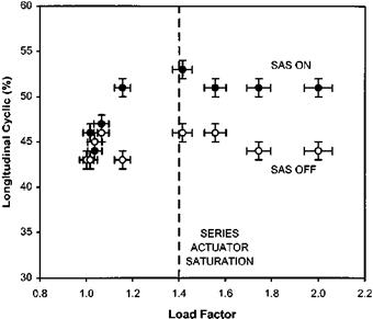
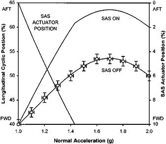
stability since any flight at reduced or elevated load factor requires the development of a pitch rate. During a pull-up manoeuvre or steady turn, the resulting pitch rate will be sensed and opposed by the SAS and in order to maintain the desired load factor additional aft cyclic will, therefore, be required. Since additional aft cyclic will be required for any load factor above unity (and vice-versa) the SAS has the effect of increasing the manoeuvre stability as seen in the cockpit, although the amount of longitudinal cyclic pitch required at the rotor head, for a given value of ‘g’, will remain unchanged. If the SAS has sufficient authority it can completely mask any tendency towards manoeuvre instability and can also prevent excessive control activity in regions when the helicopter is manoeuvre neutral/unstable by opposing the tendency to ‘dig­in’. It is usual however for series actuators to saturate at quite modest load factors, typically around 1.5g, due to the low authority inherent in that form of actuation. Consequently although with the SAS engaged there will be a greater stick migration with increasing load factor than with SAS off, the underlying manoeuvre instability of the baseline aircraft is still evident, as shown in Figs 7.10 and 7.11.

EFFECT OF AFCS ON HANDLING QUALITIES TESTING

In Chapter 6 the hardware associated with typical automatic flight control systems and the functioning of generic systems was described briefly. Although it is always important to distinguish between the functionality of stability augmentation and outer-loop or autopilot modes, a possible blurring of the definitions was pointed to when the hardware implementations of typical heading and height holds were considered. In terms of system architecture these channels tend to mimic basic pitch/roll attitude stabilization. In each case a primary sensor (compass or altimeter) is used to generate an error signal with the tightness of the hold being enhanced by rate feedback obtained from a gyro (for yaw) or integrated acceleration (for height). To provide a useful shorthand for the following discussion system based definitions of two generic forms of automatic flight control systems will be made. Thus a SAS is defined as an AFCS that provides pitch, roll and yaw rate stabilization (enhanced rate damping) and short-term attitude hold. An ASE or ATT mode AFCS is a system that provides pitch/roll attitude stabilization for enhanced stability augmentation and gust rejection via long-term attitude hold with pitch, roll and yaw rate feedback active at all times (unless disabled by the action of a trim release switch). The ASE will also provide heading hold at all speeds and possibly turn co-ordination in forward flight. It is interesting to note that these two definitions are sometimes used to describe modes provided by a dual functioning AFCS that overcomes the reduced agility commonly associated with ACAH by providing a SAS/ ASE or SAS/ATT switch to restore rate command.

7.5.1 Stability augmentation systems (SAS)

7.5.1.1 Longitudinal long-term, LDO and falling leaf modes

The additional rate damping associated with a SAS will help to suppress the nuisance modes. The action of the SAS in applying a control input in opposition to any measured rate of change of attitude will reduce the ease with which any long-term mode is excited. In addition the pseudo-attitude hold available by integrating the rate signal will provide a short-term datum to which the aircraft can be returned following minor excursions arising from atmospheric disturbances. Due to the limited authority of the series actuators employed and the low quality attitude datum, it is unlikely that these long-term modes will be completely suppressed in all levels of turbulence although an acceptable reduction in pilot workload is usually provided.

7.5.1.2 Control response

In addition to providing a reduction in pilot workload, during straight and level flight and hovering, a SAS can be employed to improve the control response. As mentioned earlier the increase in rate damping resulting from rate feedback will tend to increase control predictability by reducing the time constant (at the expense of steady state rate). Thus for any given discrete attitude change although the control will need to be displaced further the time taken for the rate of change of attitude to achieve a steady value will be reduced.

Specific testing of FADEC systems

FADEC systems are becoming increasingly prevalent in new helicopters and under­standing how to test them is an increasingly important skill for the rotary wing test pilot and flight test engineer. Essentially the testing of these systems involves the same techniques that have already been described, however, there are some areas where extra attention is required.

A key area of renewed interest is the instrumentation requirements. As FADEC systems are inherently of high bandwidth it is necessary to have a high sampling rate (>100 Hz) for data acquisition. In some systems this high bandwidth has caused the FADEC to generate damaging resonances within the drivetrain. Therefore modern instrumentation systems are designed with this possibility in mind. Extensive sets of transducers are fitted at key areas within the transmission system and there is often a capability to present the data in real time through telemetry. As the airborne environment is different from the bench, FADEC performance is checked against the results of bench tests at an early stage. To test failure modes of both hardware and

Collective pitch (deg)

Подпись: Fig. 7.9 FIG and autorotative test data.

software it is often necessary to build and test a fault injection system to simulate a range of failure modes.

Areas of specific concern for FADEC testing include: [15]

• Torque spikes. The rapid response characteristics of FADEC systems can eliminate problems with transient droop but may introduce problems with torque spikes if the gain is set too high.

• Training mode. Most FADEC systems incorporate a training mode to provide safe and realistic engine failure training. This mode is evaluated to ensure it meets its design aims. Many of these systems will restore the ‘failed’ engine to full power if Nr drops below a threshold value. The operation of this part of the system is checked with care to ensure that rapid acceleration of the engine does not lead to an overtorque.

• Failure testing. For correct operation a digital engine control system relies on software, processors and information supplied by a large number of sensors. Very extensive testing is usually required to determine the effect on the system of a failure or malfunction of any of these.

A final point to stress about FADEC testing is the need to have good configuration control over the software. During the development and testing phase a number of different standards of software may be in existence at different stages of testing. It is imperative that adequate control methods are in place so that the software version installed in the test aircraft can be tracked.

Flight idle power contribution

When helicopter pilots complain about the powerplants and governing system of their aircraft it is usually because power is not supplied quickly enough to match demand. There are occasions, however, when more power is supplied than the pilot wishes. This may happen when the pilot has lowered the collective lever fully or to a low position to descend or to reduce speed rapidly. Any power supplied by the engine(s) to the rotor when the collective lever has been lowered fully or to the collective position used in power-off autorotation is known as the flight idle glide power contribution. This situation occurs because the minimum fuel flow of the engine(s) at flight idle is set too high to allow the engine(s) to back off fully. This high minimum fuel flow may be set by the manufacturer deliberately either to prevent the poor acceleration characteristics that would occur at lower engine speeds or to avoid problems with governor stability once Nr is higher than Nf. It is important to realize that once a needle split (Nr indication higher than Nf indication) has taken place then the rotor is turning faster than the engine(s) power turbine (in percentage terms) and there can be no power contribution.

A FIG power contribution can present some serious problems. For example, if the pilot wishes to reduce speed rapidly and lowers the collective fully the undemanded power from the engine(s) will combine with the autorotational force to cause Nr to rise. The pilot will be forced to raise the collective to prevent a rotor overspeed and this will significantly reduce the rate at which airspeed can be bled off. During a quickstop manoeuvre this will result in a much increased stopping distance. A FIG power contribution will also have operational implications for rapid descents and for forced landing practice, as it will reduce the rate of descent compared to the real power-off case.

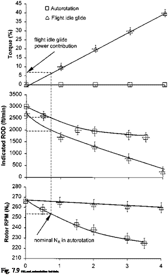
Documenting a FIG power contribution is achieved by comparing the rates of descent for a variety of collective lever positions with the engine(s) at flight and ground idle. The test is usually performed at the speed for minimum rate of descent and is conducted by timing the descent at each collective lever position through a band centred on a datum altitude. The results can be presented in the form of a plot of torque, ROD and Nr against collective lever position, as shown in Fig. 7.9. Of course the power-on line will be the static droop line. The important point on the plot is the point at which the collective position equates to the nominal Nr for a true autorotation. The manufacturer normally only gives a range of permitted Nr, therefore the test team has to decide on the nominal rotor speed to use in autorotation. This will usually be a compromise between a speed which provides sufficient rotor kinetic energy for an engine(s)-off landing and that which maintains a margin below the maximum Nr limit to account for rises in rotor speed during manoeuvring. Comparing the ROD at the collective lever position that gives the nominal Nr in autorotation with the ROD at the same lever position in a FIG allows the power contribution to be quantified both in terms of torque and decrease in ROD.