Category Management and Minimisation of Uncertainties and Errors in Numerical Aerodynamics

Application of Mesh Modifications and Adjoint Error Estimates

S. Albensoeder

Abstract. Two methods for mesh modification are considered to improve hybrid meshes for CFD calculations. The first method is an adaptation with new sensors. The new sensors are based on an adjoint approach to calculate the sensitivity with respect to a goal function. Here the sensitivity of lift, drag and pitching moment was calculated with respect to the numerical dissipation terms. The second method is a local mesh modification of the unstructured part of the hybrid mesh based on an algebraic quality measure. For an a posteriori improvement the flow properties can be included to build a new anisotropic metric. Both new methods were applied to industrial relevant test cases.

1 Introduction

One problem of today computational fluid dynamics (CFD) is the discretization of the computational domain. Due to the limits of computational resources the discret­ization of the domain is not fine enough. Therefore the discretization can have a significant effect to the results.

A common approach to reduce this uncertainty is the adaptive refinement of the grid where errors occur. In the past several sensors (e. g. gradient based, reconstruc­tion based) were developed to detect these underresolved regions. A sensor which computes the sensitivity of a discretization with respect to a specified goal function was introduced by [13]. The sensor was computed by solving an adjoint problem. One bottleneck of the method was that the final sensor was computed on the iso­tropic refined mesh instead of the original mesh. For complex configurations with a high number of grid points the demands to the computational resources are very high. In this investigation the sensors of [2] were used. This method computes the

S. Albensoeder

P3 Voith Aerospace GmbH, Flughafenallee 26, 28199 Bremen, Germany e-mail: Stefan. Albensoeder@p3voith. com

B. Eisfeld et al. (Eds.): Management & Minimisation of Uncert. & Errors, NNFM 122, pp. 55-73. DOI: 10.1007/978-3-642-36185-2_3 © Springer-Verlag Berlin Heidelberg 2013

sensitivity with respect to numerical dissipation terms. By this ansatz the error es­timation can be done without any mesh refinement step.

Another approach is the improvement of a given mesh by local modifications. This improvement can be related to improve badly shaped elements and to orientate elements in the direction of the flow.

The uncertainty due to influences of the mesh generation drives the limitation that small influences can only be computed on the same or slightly modified mesh. One example is the deformation of the geometry due to aerodynamic loads. To re­duce the uncertainty the whole mesh will be deformed to avoid a new meshing. Unfortunately this deformation can cause inverted elements which foreclose a new CFD computation. These cells have to be repaired which can also be done by the introduced local mesh modification.

In the next section the investigated methods are described. In section 3 the meth­ods were applied to industrially relevant test cases. Finally a conclusion and an outlook are given.

Conclusions for the Application

This contribution introduced three development directions of the TAU adaptation tool followed within the framework of the project MUNA, all aiming for improved adapted grids enabling for higher accuracy.

The first one, the investigation and use of the element decomposability, see Sect. 2, improves the edge refinement algorithm of the TAU adaptation. In effect as much as possible of the grid area is considered for re – or de-refinement, instead of having larger regions which are unintendedly excluded from adaptation. Under the assumption that the refinement indicator provides the correct measure for the necessity to refine edges, this step obviously improves the adapted grids. The bet­ter accuracy of the resulting solution was demonstrated for an example, using the adjoint-based error indication.

The second topic, see Sect. 3, provides an option to avoid some of the elements with a low geometrical quality introduced by standard adaptation. Because this feature is not as effective as previously thought and slightly increases the computa­tional effort, it is switched off as a default. However, the grid modification seems to be a useful option in some special situations. The idea of avoiding the worst shaped bridging elements in an adapted grid suggests to try this method in configurations with some poorly shaped elements in grid regions affecting the global solution. The stabilizing effect of the grid modification could possibly be used in examples in which the computation converges very slowly after a grid adaptation or a restart is comletely impossible. At least the option generates slight grid variations better than inserting random points. So it is an instrument for further investigation of uncertain­ties caused by grid variations.

The use of the adjoint solution for an adjoint-based adaptation, see Fig. 5, signi­ficantly improves the accuracy of the result for the target functional obtained on the adapted grids for the investigated test examples. Because of the large effort which is needed for an adjoint-based adapted computation, compared to the conventional differences-based adaptation, a careful cost-benefit analysis has to be done. Some more time and additional tests are needed to find out classes of problems and con­figurations for which one or the other method is preferable.

Error Indication Based on the Adjoint Solution

This section describes the use of the adjoint information as a sensor for the error indication in the TAU adaptation. The main work was the development and imple­mentation of the adjoint solver which is described in the contribution Adjoint-Based Error Estimation and Functional Correction of this volume. The adjoint solver provides a field variable containing a kind of measure for the local discretization error weighted with its influence on the target functional, which may be the integral lift or drag coefficent. This variable serves as an interface to the grid adaptation tool.

The work at the adaptation tool itself which was needed to enable an adjoint – based adaptation was more of technical nature. Because the provided adjoint in­formation has to be regarded as a pointwise error indicator and the adaptation tool works edge orientated, the sum of the sensor variables for the edge points has to be used as the edge indicator. Similar to the differences-based indicators, a weighted

Error Indication Based on the Adjoint Solution Error Indication Based on the Adjoint Solution

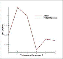
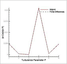
Fig. 17 Sensitivity of lift (left) and drag (right) coefficients w. r.t. variations in the model parameters P of the SAE turbulence model, calculated by adjoint method

Fig. 18 Sensitivity of lift (left) and drag (right) coefficients w. r.t. variations in the model parameters P of the Wilcox-k-m turbulence model, calculated by adjoint method combination of different variables of the adjoint sensor file can be used for error indication in the TAU adaptation.

The adjoint-based adaptation was tested in a simulation for the HIRENASD – model. The initial grid was generated with the Solar grid generator [8]. It has 3.12 million points and consists of 2.54 million hexhedra, 20758 prisms, 40430 pyramids and 3.19 million tetrahedra. The flow was calculated for a Mach number of Ma = 0.8, an angle of attack of a = 1.0° using the Spalart-Allmaras turbulence model in its original version.

After the solution was well converged, the adjoint problem was calculated for the integral drag coefficient as the target funtional. Using the adjoint sensors on the one side and the differences of gradients for comparison on the other side, the grid was

Table 6 Results of simulations using the differences-based and the adjoint-based adaptation

initial grid

adapt +50%

adapt +100%

global +353%

differences-

Cl

2.783e-1

2.787e-1

2.786e-1

2.789e-1

based

Cd

1.181e-2

1.188e-2

1.186e-2

1.171e-2

adjoint-based

Cl

2.783e-1

2.773e-1

2.774e-1

2.789e-1

target: CD

Cd

1.181e-2

1.175e-2

1.170e-2

1.171e-2

adapted with 50% and 100% new points. Table 6 shows the results of the integral lift and drag coefficents. These results are compared to the results for the initial grid and the globally refined grid. As already discussed in Section 2 and Subsection 3.2, the result on the globally refined grid serves as reference value in case of a locally adapted calculation.

The differences-based adaptation leads to improved results for the lift coefficient, but not for the drag coefficient. It seems that the differences are not appropriate for estimating the local discretization error in this example. Contrary, the adjoint-based adaptation improves the results for the drag coefficient significantly. Because the drag coefficient was used as target functional for the adjoint-based adaptation, an improvement of the lift coefficient result is not expected in this case.

The process was restarted for the example with 50% new points. The results are documented in Table 7 and the resulting grids of the adjoint-based case are shown in Fig. 19. The adaptation used re – and de-refinement and the twice adapted grid has some de-refined grid areas.

The adjoint-based adaptation is significantly more expensive in terms of compu­tational effort. The differences-based adaptation usually can already be performed for a not fully converged solution, especially in case of a computation with mul­tiple adaptations. The resulting grid will not differ very much from that generated by adaptation for the fully converged solution. Different from that, an adjoint cal­culation requires a very well converged solution. Additionally, the adjoint solution needs computational resources comparable to the original solver and nearly an order of magnitude more memory.

The application of the adjoint-based adaptation requires a careful choice of the control parameters to get the best effect from the much better, but expensive error

Table 7 Results of a twice adapted simulation using the differences-based and the adjoint – based adaptation

initial grid

adapted +50%

2x adapted +50%

differences-

Cl

2.783e-1

2.787e-1

2.790e-1

based

Cd

1.181e-2

1.188e-2

1.190e-2

adjoint-based

Cl

2.783e-1

2.773e-1

2.780e-1

target: CD

Cd

1.181e-2

1.175e-2

1.177e-2

Error Indication Based on the Adjoint Solution

Error Indication Based on the Adjoint Solution Error Indication Based on the Adjoint Solution

Fig. 19 Grids resulting from adjoint-based adaptation: initial grid (top left), once adapted grid (top right), twice adapted grid (bottom)

estimation. For example, if the percentage of new points is chosen too small, the differences-based adaptation might achieve the same result, using much more points with a similar computational effort. On the other hand, the point number and the resulting grid should not get near the global refinement. In this case the influence of a better refinement indicator would be smaller.

Thus, further systematical tests are needed to find a best practice strategy for the adjoint-based adaptation.

Adjoint-Based Error Estimation and Functional Correction

Подпись: 0 .
Подпись: dI -r dI dU + W dU
Подпись: (10)

An efficient and consistent way of estimating numerical errors in a functional I(U) of interest, are the so-called dual weighted residual approaches (DWR). Here, one weights the numerical error, represented by the residual R(Uh) of the numerical state solution Uh approximating the exact solution U, by the so-called dual or ad­joint state. The idea stems from Johnson, Rannacher et al. [6] in the Finite Element Method (FEM) context. The reason for the weighting of the (local) residual with the adjoint field vector у is, because the adjoint is an influence function (i. e. a Green’s function) w. r.t. the functional of interest I, for which one has solved the adjoint state equation

The adjoint field vector has value zero in areas with no impact on the functional I(U), and (very) different from zero in areas of (big) impact. This means, that the adjoint as a weight eliminates local residuals in areas where the error only appears, and increases it in areas where the errors come from.

Unfortunately, there is a difficulty in transfering the DWR to Finite Volume Methods (FVM). The reason is, that one would need the exact adjoint solution for the calculation of the first order error term. Instead, one solves in FEM context the adjoint problem with higher order test and ansatz functions, and this yields then the first order error estimate. But in standard FVM, it is not possible to play around with the order of test and ansatz functions.

One possibility to overcome this difficulty is the repeated extrapolation between certain mesh levels (e. g. from coarse level H to globally refined level h) as suggested by Venditty and Darmofal [13] or Pierce and Giles [10]. This approach has been proved to lead to a good error estimate, given as

Ih(UH) – Ih(Uh)« {whHГRh(UH), (11)

but is not handy e. g. in areas of shocks and w. r.t. memory consumption (due to values needed at globally refined mesh level h).

An alternative idea by Dwight [5] is, to interpret the discretization error R(Uh), at least for the central Jameson-Schmidt-Turkel scheme available in TAU, as dissip­ation error. This yields instead of

Adjoint-Based Error Estimation and Functional CorrectionAdjoint-Based Error Estimation and Functional Correction

Fig. 15 Adjoint-based error sensor for lift (left) and drag (right) to the error estimate

m,)-m « vf (t,2) H+t’41^i) • (13>

Here, k(2) and k(4) are the scaling coefficients for the dissipation of second and forth differences, i. e. first and third order. It turns out that this approach is accurate enough and obviously it is very handy.

This method has been implemented by R. Dwight in the TAU code and has been used by the authors within the project MUNA.

Подпись: Wh Adjoint-Based Error Estimation and Functional Correction Подпись: i, j,k Подпись: (14)

The right hand side of Equation (13), the global error estimate, is to be under­stood as the integral or sum of the local error estimates

at cell positions Xi, j,k, and (14) can be used as an indicator or sensor for adjoint – based (and therefore) goal-oriented mesh adaptation. For the realization and applic­ation of this local adjoint-based sensor for mesh adaptation in TAU, we refer to Section 5.

In this Section we first present the validation of the local and global adjoint-based error estimate. The difficulty in the validation here is, that one should know about the exact solution to compare with. Therefore, we have chosen an inviscid subsonic NACA0012 flow case and drag as functional of interest. Then we know, that the exact (shock less) solution has zero drag. (Only some spurious drag, i. e. numerical dissipation, remains.)

Figure 15 shows the local sensor (14) for lift and drag. That these sensors, which are the local error estimates, lead to good global error estimates, can be seen in Figure 16.

Furthermore, the adjoint method is used for the efficient quantification of uncer­tainties in the aerodynamic coefficients caused by variations of the model

Adjoint Based Error Estimate / Functional Correction

Подпись: •— C_D(inffial mesh) ■ C_D(global refined mesh) ■ C_D(corrected by estimate) Подпись:Adjoint-Based Error Estimation and Functional CorrectionNACA0012

Ma = 0.5 a = 1.0°

Q

Adjoint-Based Error Estimation and Functional Correction Adjoint-Based Error Estimation and Functional Correction Adjoint-Based Error Estimation and Functional Correction

О

Adaptation

Fig. 16 Adjoint-based global error estimation and functional correction for the drag coeffi­cient on initial and globally refined mesh (NACA0012, Ma = 0.5, a = 1.0°, inviscid) parameters of the SAE and the Wilcox-k-ю turbulence model. Compared to finite differences one is here independent of the number of model parameters w. r.t. the nu­merical costs. Figures 17 and 18 show a good match of the sensitivities calculated by the adjoint method as well as by finite differences for lift and drag coefficients, caused by variations in the model parameters of SAE and Wilcox-k-ю.

Results on Modified Grids

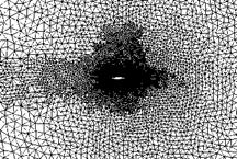
As a more realistic test case, the flow around the DLR-F6 model has been taken. The initial grid was prepared with the Centaur grid generation tool [3], see Fig. 13.

The simulation was done for Mach number of Ma = 0.75, an angle of attack of a = 0.00, using the Spalart-Almaras turbulence model in the original version (SAO). After the simulation on the initial grid was fairly converged, the adaptation was performed to increase the point number by 50%, using differences of the solu­tion gradients for refinement indication and using various values of the modification parameter. The modification parameter defines the portion of elements which is con­sidered for only regular refinement. In the test series it was increased from a value of 0, i. e. no modification, to a value of 0.1, the maximum value allowed. Table 3

Подпись: Fig. 13 Surface of the initial grid of the DLR-F6 model used in the test example for the modified adaptation, containing 2.46 million points, 1.87 million prisms and 8.66 million tetrahedra
Results on Modified Grids

shows the different modification parameter values, the actually inserted percentage of new points and how much of these new points are inserted by the edge indicator.

Table 3 List of tested modification parameter values, i. e. the portion of elements prepared for only regular refinement, the actual increase of the adapted grid and the portion of new points which was inserted by the initial edge refinement (and not by the modification)

modification

parameter

0.000

0.001

0.002

0.005

0.010

0.020

0.050

0.100

new points in %

49.95

50.02

50.10

50.03

50.31

50.26

50.40

50.47

portion of new points initially inserted in %

100.0

95.26

93.85

90.85

86.66

78.37

49.49

10.60

With an increasing influence of the modification, i. e. with a larger number of elements considered for regular refinement only, the portion of points inserted by indicators decreases, because a lot of points are needed for the regular refinement of badly shaped elements. The table shows that increasing the modification parameter beyond 0.05 seems to be not a reasonable choice in this example, because the ratio of points spent for adaptation of the grid resolution and points spent for the quality manipulation is too small.

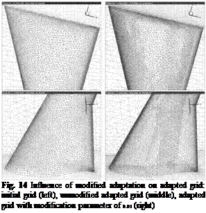
The differences of the surface grids for the unmodified case and the case using the modification parameter 0.01 also show this effect, see Fig. 14. In the modified case less points are used to refine the area of the shock system. These points are moved to some badly shaped elements to improve their subdivision. Because these changes mostly are done locally at places where refinement already occured in the unmodified case, it is hard to find them in the picture. They are located in the areas of the wing-body intersection and behind the trailing edge. In these areas probably the convex or concave geometry forced the grid generation tool to introduce some elements of lower quality.

Подпись: Fig. 14 Influence of modified adaptation on adapted grid: initial grid (left), unmodified adapted grid (middle), adapted grid with modification parameter of 0.01 (right)
Results on Modified Grids

The results for the integrated lift and drag coefficents and the residuals after 2000 and 10000 solver iteration steps after the adaptation are listed in the table 4. The results are compared to the corresponding results on a globally refined grid. The globally refined grid includes all the refinements that any local adaptation could do, and the element quality is perfectly preserved because all subdivisions are regular. So the result on the globally refined grid are the best what a local adaptation is able to achieve. The grey-shade of the entries indicates if the result is more accurate or smaller in case of a residual than the corresponding value for the unmodified case. Black entries are better, grey entries are worse than the value of the unmodified case. In this example the best results are achieved with a modification parameter of

0. 005-0.010.

Another test example was a simulation on a Solar [8] grid for the HiReTT model. The initial grid has 3.61 million points and consisists of 3.16 million hexahedra, 25675 prisms, 81396 pyramids and 2.27 million tetrahedra. The calculation was

Table 4 Residuals and results of various adaptation modifications for the DLR-F6 model

modif. Ref. 0.000 0.001 0.002 0.005 0.010 0.020 0.050 0.100

param.

Res. 12k 6.864e-4 7.452e-4 7.185e-4 7.012e-4 5.244e-4 5.616e-4 6.114e-4 8.682e-4

Res. 20k 4.533e-5 4.466e-5 4.507e-5 4.452e-5 4.689e-5 4.627e-5 4.516e-5 5.302e-5

CL 4.581e-1 4.613e-1 4.610e-1 4.606e-1 4.594e-1 4.591e-1 4.597e-1 4.663e-1 4.656e-1

CD 2.665e-2 2.730e-2 2.728e-2 2.728e-2 2.727e-2 2.728e-2 2.727e-2 2.723e-2 2.721e-2

Table 5 Residuals and results of various adaptation modifications for the HiReTT model

modif.

param.

Initial

Global

0.000

0.002

0.005

0.010

0.020

new points in %

102.07

103.28

96.39

100.18

97.28

portion of new p. initially inserted

71.77

70.93

69.31

66.69

57.93

Res. 4000

8.621e-6

8.775e-6

8.816e-6

8.167e-6

6.601e-6

Res. 6000

1.354e-6

1.339e-6

1.320e-6

1.271e-6

1.128e-5

Cl

2.156e-1

2.143e-1

2.146e-1

2.146e-1

2.144e-1

2.145e-1

2.144e-1

Cd

1.024e-2

9.941e-3

9.962e-3

9.962e-3

9.962e-3

9.964e-3

9.971e-3

done for a Mach number of Ma = 0.85, an angle of attack of a = 0.0°, using the Spalart-Allmaras turbulence model in the original version. After 3000 solver itera­tion steps the grid was adapted with 100% new points, using the differences of the primitive variables as the refinement indicator. Again, the adaptation was applied using the standard version and various values of the modification parameter.

Table 5 summarizes the results of the adaptation and the following calculation. In this example the best result is achieved for a modification parameter of 0.005. In this case the lift coefficient is approximated a little better, and the deviation of the drag coefficient is not increased.

Some more test calculations for the LANN-wing and the HIRENASD-wing con­sidering the modified adaptation were done. Summarizing the experiences from all tests performed until now, the following remarks can be made:

1. The influence of the described adaptation modification on the results of integral lift and drag coefficients is small compared to the influence of other parameters, e. g. the number of grid points or the turbulence model.

2. The results are almost never worsened for small values of the modification para­meter compared to the results using the unmodified adaptation.

3. The results get worse or unpredictable, if the modification parameter approaches the maximum value of 0.1.

4. The influence of the adaptation modification seems to be larger when introducing fewer («50%) new points than more («100%) new points in one adaptation step.

5. The residuals tend to fall faster for larger modifications in the first (1000-2000) solver steps after adaptation.

6. If the computation converges well, the residuals for smaller grid modification are often smaller than that for larger grid modification for the converged solution.

The reasons for the unexpected small influence on the results by this adaptation op­tion may be manifold. One possible explanation is that the element shape is less important for the local discretization error than the resolution of the considered examples and grid types. Another interpretation is that the red-green refinement strategy of the TAU adaptation is well suited for the considered grids, i. e. the loss

of element quality in bridging refinements does not affect the solution very much. See Sect. 6 for conclusions regarding the application.

Modification of Adapted Grids

The idea of grid modification is to avoid bridging refinements for elements of lower geometrical quality. The borders between different refinement levels are moved into elements of a better quality, see Fig. 11.

Подпись: initial elements regular refinement bridging refinement
Modification of Adapted Grids

Fig. 11 Idea of the grid modification: the initial elements are of various quality (left), the unmodified adaptation leads to bridging elements of even lower quality (middle), moving the bridging refinements to better initial elements avoids the worst elements (right)

The bridging refinements, the so called green elements of the red-green-method, tend to provide children of a lower quality in comparison with the parents and the corresponding children of a regular refinement. So this method can avoid the worst elements of an adapted grid.

To explain the problems of the method, some algorithmic details are needed. An internal edge refinement trial of the TAU adaptation has three main steps. First as much as possible points are (temporarily) removed. In the second step, the initial refinement is done depending on the error indicators of edges and the target size of the grid. Then, points are added iteratively until all elements have a valid subdivision state as a third step.

The only place for the modification is the third step, because in the second step the initial borders between refinement levels are determined. Because a bridging re­finement can not taken back in this step it has to be re-refined to a regular one. So additional points are needed for the modification. Furthermore, the regular subdivi­sion of a badly shaped element provides more badly shaped child elements than the bridging subdivision. Therefore, regarding the pure numbers, the portion of badly shaped elements could increase though their quality is not worsened in a modified adaptation.

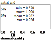
As a first test the triangles of a two-dimensional grid around a RAE-2822 air­foil are adapted without modification and with a forced regular refinement for all elements with a quality lower than a limit of 0.98, see Fig. 12.

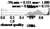
The quality distributions of the adapted grids have much more elements of lower quality than the initial grid. These are the elements of bridging subdivisions. The modified adaptation can avoid the low quality elements of a quality 0.33-0.5 be­cause they come from bridging subdivisions which become regular ones in the mod­ified case. The portion of high quality elements with quality 0.98-1.0 decreases in the modified adapted grid because a lot of them has to be refined nonregularly, tak­ing the borders of various refinement levels in the modified adapted grid. Because of both effects the behaviour of the average quality of all elements after modification cannot be predicted. In this example it is nearly unchanged.

In three-dimensional cases of more complex geometries the element qualities of the initial grids are usually much broader distributed. That is why these effects are overlaying for various qualities. So there are quality slots for which some bridging

Fig. 12 Element quality distribution of a test: initial grid (top), unmodified ad­apted grid (left), modified adaptation (bottom right), showing the percentage of elements in quality intervals of the length 0.01. The light – grey bars are oversized to the tenfold.

Подпись: initial grid 5% min = 0.570 max= 1.000 3% mean = 0.982 var = 0.026 0.0 0.2 0.4 0.6 0.8 1.0 element quality Подпись:Подпись:

Modification of Adapted Grids Подпись: - 5% min = 0.508 max= 1.000 mean = 0.930 var = 0.108 0.0 0.2 0.4 0.6 0.8 1.0 element quality

adaption (quality limit: 0.98)

elements are avoided by the modification. But some additional elements from regu­lar subdivisions fall into the same slot to avoid elements of even worse quality.

The implemented version of the grid modification requires an input parameter defining the portion of elements which is to be considered for only regular refine­ment. The TAU adaptation determines the actual quality limit from this portion. In order to have the same behaviour in various adaptation steps, the portion and the limit refer to the initial grid. Furthermore, if an element which is considered for regular refinement has an unrefinable edge, this element is not refined at all.

A Geometric Quality Measure for the Element Types of TAU

The geometrical quality measure has to be defined for all element types used in TAU, and the choice has to consider the available information and experience about the relation between element shape and discretization error. The high aspect ratio of hexahedra or prisms for example is needed to simulate flows with anisotropic char­acter. The analytic preliminary investigations also confirmed that the aspect ratio of quadrilaterals does not contribute to the element shape related discretization error in an otherwise regular grid.

A Geometric Quality Measure for the Element Types of TAU A Geometric Quality Measure for the Element Types of TAU A Geometric Quality Measure for the Element Types of TAU Подпись: (1) (2)

Without a good reason not to do so the most simple measure is chosen for the unstructured part. A very simple and well known geometrical quality measure for simplices is the mean-ratio shape measure, e. g. [4]:

This is the ratio of the geometric and the arithmetic mean of the eigenvalues Xi of the linear transformation to the regular element. The resulting formulae for triangles (1) and tetrahedra (2) have a representation in terms of the element area A and the edge length a, b, c and in terms of the volume V and the edge length eij, respectively.

Most quadrilateral quality measures suggested in publications are derived from triangle quality measures such that high aspect ratios mean a low quality, e. g. [9]. So they are not applicable to TAU. Here another approach is tried. Instead of de­composing the quadrilateral and applying the triangle formula to the pieces, here the formula is decomposed and the parts interpreted as penalty terms of certain geo­metrical distortions. The analogue application to quadrilaterals shows how the term has to be modified to get a useful formula for TAU.

Подпись: Qtri Подпись: 4A/3A a2 + b2 + c2 Подпись: fba |fc + c| sinф a2 + ^a2 +  b + c2 Подпись: sin ф ■ Подпись: 1 2 A Geometric Quality Measure for the Element Types of TAU Подпись: (3)

By means of the vector analysis the following representation of the mean-ratio quality for triangles can be found:

This can be considered as a decomposition of the mean-ratio quality into a term sin ф for the evaluation of distortion and a second term evaluating the stretching of the triangle. The stretching related term again has a mean ratio structure. It is the ratio of geometric and arthmetic mean of |tz| and | ^ | which are equal for a regular triangle. The decomposition into distortion and stretching depends on the choice of the triangle base side. This does not matter because the triangle formula will not be changed and the analogue formula for quadrilaterals which has to be changed will not depend on an arbitrary choice. Figure 7 shows the further proceeding.

The analogue formula considering distortion and stretching in the same way for quadrilaterals (4) does not include deviations from parallelism. So Q*uad can be considered as quality measure for parallelograms, see Fig. 7, middle part. In order to get a useful quality measure for TAU, the mean-ratio term evaluating the stretching is neglected and a term X for evaluation of the nonparallelism is added.

A Geometric Quality Measure for the Element Types of TAU A Geometric Quality Measure for the Element Types of TAU

Fig. 7 Steps of derivation of the geometrical quality measure for quadrilaterals: interpretation as stretching and distortion (left), construction of the analogue measure for a parallelogram (mid) and addition of a term to evaluate the deviation from parallelism (right)

The choice of the term X is determined by the mean-ratio principle and the defin­ition of a correct element quality measure. This includes that this measure is zero for a completely collapsed or otherwise distorted element. A measure is needed to evaluate elements of the TAU Code in a reasonable way. So an element has to be con­sidered as completely distorted, if one of its triangle or tetrahedra parts collapses. The definition of X as the mean ratio, i. e. the ratio of geometric and arithmetic mean, of the triangle part areas meets both requirements, see Fig. 7, right part. The resulting quality measure for quadrilaterals Qquad can be expressed by formula (5).

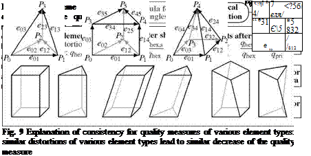
The application of this idea to the three-dimensional case includes a geomet­rical interpretation and a decomposition of the mean-ratio quality of tetrahedra. In this calculation the terms describing the base triangle can be replaced by the ana­logue terms for quadrilaterals, see Fig. 8, upper part. In this way a consistent quality measure for pyramids is derived. The quadrilateral quality can be generalized to hexahedra, considering the relation of triangle and tetrahedra quality. An applica­tion of this step to triangle bases leads to a quality formula for prisms, see Fig. 8, lower part.

This procedure ensures a kind of consistency between the quality measures of various element types. In this context consistency means, that similar distortions applied to elements of various types lead roughly to the same decrease of the ele­ment quality for both element types, see Fig. 9.

This feature is very valuable for the use in adaptation algorithms. It could be used in the investigation of element subdivisions. For example, if a hexahedron of the structured layers is refined to bridging prisms, the prisms roughly inherit the quality of the parent hexahedron, and their quality is decreased by the horizontal stretching which was not relevant for the parent hexahedron. This decrease is nearly independent of the initial quality of the parent.
A Geometric Quality Measure for the Element Types of TAU
After all the needed calculation, we get the following formulae for the geometric quality measures of the various element types, equation (6)-(9). Figure 10 provides the notation of edges used in the equations.

Fig. 10 Notation of the edges of element types used in the formulae of geometric quality

with V0 — |e01, Є02 + Є12, Є03 + Є14 + Є251 ,••• and V01 — |e0b e02 + e12 + e35 + e45, e03 + e14| ^- ,

6v3 ^01,^03 + ^12,£4! • кз2+03+^1 2,-Е’4і ‘ koi + ^32+03,+4І • Qpyra = 3 ‘

+ ^32 )2 + 2(^03 + ^ 12 )2 + +4^ •

Подпись:

A Geometric Quality Measure for the Element Types of TAU
Подпись: (6)
Подпись: Qprism Подпись: (7)

•коі+ез2,еі2,£4|) Г • ((еоі+^зг)2 + (Gb+^g)2) ‘ koi + ^321 • коЗ + ^12І with E4 — e04 + e14 + e24 + e34 ,

•коі + е32,^12,Д2І • к45+47 + ^5б,£’2І • • • • • 1+0 +03 +04 + ^371 • • • •

ІЕ0І • |+11 • 1+21

24

••• • |e01, E1, e04 + e15| • ••• • |e32 + e76, E1, e26| )

————————————————————– (9)

with E0 — e01 + e32 + e45 + e76 , E1 — e03 + e12 + e47 + e56 and E2 — e04 + e 15 + e26 + e37 •

The incomplete products in equations (7) and (9) go over all the tetrahedra parts of a prism and a hexahedron, respectively. The expression ^,y, z| — (x x y) • z denotes the triple product which can be calculated as a determinant of the vector entries.

Modification of Adapted Grids on the Base of a Geometrical Element Quality

The background of another new option of the TAU adaptation is that the error es­timation, of advanced adjoint-based methods as well as of simple differences-based methods, determines a new point density for the initial grid. On the other hand, the local discretization error depends on the local resolution and probably on the element shape and alignment. So the ideal grid adaptation would adapt the point density without changing or at least without worsening the element shape. This is impossible for a hierarchical conform refinement as the TAU adaptation performs.

The preferable solution was to evaluate the influence of the element shape on the local deiscretization error and to consider the result when determining the refine­ment state. However, the attempt to estimate the numerical error by evaluating the numerical fluxes in the control volume or at least the first derivative of a variable for the methods used by TAU lead to very complex formulae and a large diversity of possible element configurations around a point. Because of the low prospect of success this trial was abandoned. In the mean time, a similar problem seems to be solved for the two-dimensional case, using symbolic computations [7].

Partial results of the analytical investigations suggest that the local discretization error is comparatively small for uniform grids. Therefore, it seems to be worthwhile considering a geometrical element quality [2,4, 12] for replacing the element shape related part of the local discretization error. The main problem of this approach seems to be that the converse argument is not true. Grids or areas with apparently low element quality may provide good dual grids in terms of rectangularity of dual edges and faces.

Improvements Using the Decomposability of Elements

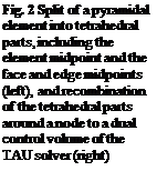
According to the red-green-type of refinement and the edge-oriented methods of the TAU adaptation, a lot of various types of element decompositons are needed for each element type. The decomposability of a special element means its geometrical characteristics which determine which subdivisions can be applied to this element. A special subdivision is applicable to an element if the resulting child elements are admissible for the TAU solver. Elements are admissible if they can be split into tetrahedral parts using the midpoints of the element, of the element faces and edges, see Fig. 2. Each of these tetrahedral parts has to have a positive volume, i. e. has to be correctly orientated, because the dual control volumes for the TAU solver are built out of them.

The problem is trivial for tetrahedra. Each tetrahedron with a positive volume has a mid point decomposition into positive tetrahedral parts. Furthermore, each refinement of a tetrahedron resulting from subdivision of some of its edges provides child tetrahedra with positive volume only. So even a very stretched tetrahedron has the full decomposability quality in this sense. This is not true for the other element types. Mainly because of nonplanar quadrilateral element faces, the similarity of the descendants and the initials does not hold as for tetrahedra.

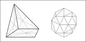
Подпись: Fig. 2 Split of a pyramidal element into tetrahedral parts, including the element midpoint and the face and edge midpoints (left), and recombination of the tetrahedral parts around a node to a dual control volume of the TAU solver (right)
Improvements Using the Decomposability of Elements

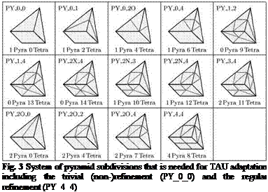
Pyramids are not only part of bridging refinements between various hexahedra refinement levels, they also bridge between hexahedra and tetrahedra of hybrid grids and at prism sides in case of a varying number of prism layers. Thus pyramids have the most complicated system of subdivisions in the TAU adaptation, see Fig. 3. That is why the following consideration is done for the example of pyramids.

The admissibility conditions for the descendants of a special element subdivi­sion can be expressed in terms of the edge vectors of the initial element. The vector analysis yields the corresponding conditions for the initial element needed to ful­fill the decomposability condition for each single subdivision. The results of this investigation are presented in Tab. 1. The notation used in the formulation of the decomposability is introduced in Fig. 4.

Подпись: Fig. 3 System of pyramid subdivisions that is needed for TAU adaptation including the trivial (non-)refinement (PY_0_0) and the regular refinement (PY_4_4)
In order to see how the exact knowledge about the possible refinements is used, some details of the adaptation algorithm are needed. There are two critical points: the first one is that most grids have some unrefinable edges, at least for the TAU adaptation. That can be the vertical edges of hexahedra and prisms of the structured and semistructured areas for resolving boundary layers. There are badly shaped

A WT^Pi ~

Table 1 Decomposability conditions for pyramids

Level

Decomposability conditions

Possible refinements

Pyr-F

Vi + Vj-1 < 0 for one i = 0,1,2,3

pyramid is not admissible

Pyr-0

Vi + Vi-1 > 0 for all i = 0,1,2,3

PYRA_0_0, PYRA_2X_4, PYRA_1_2,PYRA_1_4

Pyr-1

3V + Vi-1 > 0 und V + 3V-1 > 0 for all i = 0,1,2,3

PYRA_2N_3, PYRA_2N_4, PYRA_3_4, PYRA_4_4

Pyr-2

2V+1 – V+V-1 > 0 and V+1 – Vi+2V-

and V > 0 for all i = 0,1,2,3

A > 0 PYRA_0_1, PYRA_0_2O, PYRA_0_4, PYRA_2O_0

Pyr-3

V+1 – V+Vi-1 > 0 and V > 0 for all i =

= 0,1,2,3 PYRA_2O_2, PYRA_2O_4

elements which cannot be refined at all in some grids for complex geometries. Fur­thermore, depending on the TAU adaptation version, there are elements which have no implemented refinement, e. g. hexahedra apart from the boundary layers or hexa – hedra which cannot uniquely be assigned to one stack up to now.

The second point is that the initial edge refinement by the edge indicator runs through the grid to some extent. Starting from the initial refinement, additional edges have to be refined due to the red-green method and in order to preserve the layer structure at boundaries. Because not all element types have a subdivision case for each combination of marked edges, additional edges have to be marked in order to find a valid refinement case.

If this ongoing edge subdivision runs onto an unrefinable edge, the adaptation will fail with an invalid subdivision state for an element and crash. Earlier versions of the TAU adaptation used the following method to avoid this situation:

Earlier method:

1. Find unrefinable edges.

2. Mark all edges of a 5 elements deep environment around unrefinable edges as forbidden for initial subdivision.

3. Do the initial subdivision due to the edge refinement indicator for allowed edges only.

4. Loop over all elements:

Subdivide additional edges (including the forbidden and reflnable edges) until a valid refinement state is reached.

The depth of 5 not initially refined elements was needed for stability in applica­tion examples with repeated adaptation. In this way large parts of the refinable grid area were excluded from adaptation. The preliminary investigation of the decom – posability quality enabled the following improvement of the method:

Improved method:

1. Find unrefinable edges.

2. Check the decompositon quality for each element.

3. Loop over all elements:

Mark additional edges as unrefinable until each initial refinement leads to at least one valid refinement state.

4. Do the initial subdivision due to the edge refinement indicator for all refinable edges.

5. Loop over all elements:

Subdivide additional edges until a valid refinement state is reached.

The influence of the improved method was tested with a simulation of the flow around the HIRENASD wing. The initial grid was a SOLAR-grid [8] with 3.12 million points. After the solution was fairly well converged, the grid was adapted with 50% new points using the adjoint-based error indication and the integral drag coefficient as the target functional, see contribution Adjoint-Based Error Estimation and Functional Correction of this volume and Section 5. In case of adaptation to a target functional, the accuracy of the result for this functional is obviously a criterion for the performance of the adaptation.

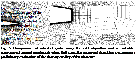
The influence of the various refinement algorithms can be observed in a cut for y = 0 near the symmetry plane behind the trailing edge, see Fig 5. The adapted grid resulting from the earlier algorithm has much less points in this area. It can be supposed that this is due to the five elements deep environment of edges forbidden for the initial refinement.

A zoom into the grid around the trailing edge actually shows the unrefinable edges, see Fig. 6. The grid for the boundary layer consists of hexahedra stacks on the wall. They are depicted as quadrilaterals in the cut planes. But there are two stacks on the sides of prisms. These prisms are depicted as triangles at the lower corner of the thick trailing edge in the cut plane in the right side of Figure 5. The prisms alone would not prevent refining the attached hexahedra stacks. But the prisms form two chains along the trailing edge perpendicular to the cut plane and at the other end of

Improvements Using the Decomposability of Elements
the prism chain, at the wing tip, a badly shaped pyramid is attached. Some edges of this pyramid are vertical edges at the same time.

The old algorithm starts at the unrefinable vertical edges, finds that the bad shaped pyramid only can be refined at once. Thus the entire pyramid is unrefin­able. Because the TAU adaptation considers the attached prism chain as a stack, the corresponding edge stack would also be refined at once. Hence the algorithm which forbids the environment has to go through the prism chain in one step. Also, the al­gorithm has to go through the hexahedra stacks at the prism sides in one step. Finally it propagates into the tetrahedra area, affecting some of the neighbouring hexahedra stacks. Unfortunately this affects the whole trailing edge. The new algorithm does not need the five elements deep environment of forbidden edges. Therefore only the hexahedra stacks at the prisms are forbidden for initial refinement and not addition­ally the neighbour stacks and tetrahedra around them.

The results for the different adapted grids and the initial grid and for a globally refined grid as reference result are given in Table 2. The solution on the globally refined grid is a useful reference value for a solution on a once only locally adapted grid because the globally refined grid has in each region the best state which any local refinement could have regarding the resolution and element shapes.

The comparison shows that the drag is evaluated more accurately on the grid adapted using the improved algorithm. The result of the lift also is approximated better in comparison to the result on the initial grid. Because the target functional of the adjoint-based adaptation was the drag, the better adaptation algorithm does not have to result in a better approximation of the lift coefficient.

Table 2 Results of the test example

value

initial grid

adapted (old)

adapted (new)

global refined

Cl

2.783e-1

2.788e-1

2.787e-1

2.789e-1

CD

1.181e-2

1.180e-2

1.179e-2

1.171e-2

Quantification and Reduction of Numerical Uncertainties by Improvement of the TAU Grid Adaptation Tool and Adjoint Methods

Matthias Orlt and Nicolas R. Gauger

Abstract. Within the framework of the project MUNA, several enhancements of the grid adaptation tool of the DLR TAU Code were prepared, implemented and tested. Therefore, various quality aspects of the single elements of the computational grid were investigated and used to modify the adapted grids.

Conditions for the decomposability of the elements are evaluated and used for a more accurate compliance of the point density with the requirement of the error indicator in the grid refinement. Geometrical element quality terms for the element types of the TAU Code are derived from the known mean-ratio element quality meas­ure for a simplex and used to avoid the worst shaped elements in an adapted grid.

In addition, the TAU adaptation was extended to use the sensors provided by the adjoint solver of TAU as an error indicator for a goal orientated grid adaptation. The results are compared to that of a simple differences-based grid adaptation.

Furthermore, the adjoint method was used for the efficient quantification of un­certainties in the aerodynamic coefficients caused by variations of the parameters of the SAE and the Wilcox-k-m turbulence model.

1 Introduction

The goal of any grid adaptation in the solution of partial differential equations is to achieve the highest possible accuracy with the lowest possible effort. Under the assumption that the largest local discretization error affects the solution, the best one can do is to equidistribute the discretization error. So grid adaptation has two main

Matthias Orlt

German Aerospace Center (DLR), Institute of Aerodynamics and Flow Technology, C2A2S2E, Bunsenstr. 10, D-37073 Gottingen, Germany e-mail: matthias. orlt@dlr. de

Nicolas R. Gauger

Head of Computational Mathematics Group, Department of Mathematics and

Center for Computational Engineering Science (CCES), RWTH Aachen, (formerly DLR)

e-mail: gauger@mathcces. rwth-aachen. de

B. Eisfeld et al. (Eds.): Management & Minimisation of Uncert. & Errors, NNFM 122, pp. 29-53. DOI: 10.1007/978-3-642-36185-2_2 © Springer-Verlag Berlin Heidelberg 2013

Quantification and Reduction of Numerical Uncertainties by Improvement of the TAU Grid Adaptation Tool and Adjoint Methods

Fig. 1 Example of a grid adaptation around an airfoil, showing the initial grid (left) and the twice adapted grid (right) with different refinement levels and bridging elements between them

steps. The local discretization error is estimated and then the point density is changed. In areas with larger local errors the point density is increased and vice versa.

The TAU adaptation [1] is basically a hierarchical grid re – and derefinement using a special variant of the red-green-method and it works edge orientated. This means edge indicators are determined as numbers specifying the necessity to be refined or derefined for each edge. Depending on the available resources, i. e. a target point number, points are added to or removed from edges. In order to build a new grid from the new points some elements have to be subdivided and some have to be recomposed according to subdivided or rejoined edges.

The advantage of this method is, that it is fast compared to a local remeshing and that it can very accurately fulfill the edge indicator requirements. On the other hand a lot of elements are not refined completely because some refinements have to bridge between various refinement levels in order to get a conform adapted grid. Additionally, the refined area can be very scattered over the grid. This leads to even more bridging elements or nonregular refinements, see Fig. 1.

In order to preserve the semistructured character of the grid near walls in hybrid grids, the vertical edges of the prisms or hexahedra in layers are not subdivided. In areas with chopping, the vertical edges are edges of unstructured elements, too. If such elements are refined it has to be done nonregularly. Moreover there are some­times badly shaped elements which cannot be refined at all because even a regular refinement would lead to elements which cannot be split into positive tetrahedra parts for the dual computational grid of the TAU solver [11]. Especially large grids for complex geometries tend to include some of such elements, mostly with non­planar quadrilaterals.

The problem of refinement restrictions in conjunction with the element shape around unrefinable edges is addressed in the next Section 2 under the term element decomposibility. In this topic, the investigation of the geometric conditions for the validity of resulting elements enabled for an improvement of the edge refinement algorithm and led to a better compliance of point distribution with the requirements of the error indicator in the adapted grids.

In most cases, the element quality in terms of edge length relation and inner angles of the nonregular bridging refinements is lower than for the corresponding regular refinement. The following Section 3 deals with the element shape of bridging refinements under the term of geometrical element quality. Appropriate element quality measures were derived for the element types used in the TAU Code. After a second modification, the TAU adaptation got the option to avoid the nonregular subdivision of badly shaped elements in order to limit the worsening of the element quality in conjunction with bridging refinements.

The last topic is the use of the results of the adjoint solver as a sensor for the edge indicator of mesh adaptation. Furthermore, the adjoint method is used for the efficient quantification of uncertainties in the aerodynamic coefficients caused by variations of the parameters of the SAE and the Wilcox-k-ю turbulence model. For a description of the work at the adjoint solver and the possibility to consider parts of its results as an error estimator we refer to Section 4. The TAU adaptation related work at this point made the adjoint-based sensor available for the internal edge indicator and enabled for an adjoint-based adaptation. Some first tests were done within the project. They are presented and discussed in Section 5.

The three modifications include a better error indication, a more accurate adapt­ation to the required point density and a check of the geometrical element quality. Each of them aims at the reduction of the numerical uncertainty.