Category MECHANICS. OF FLIGHT

Effects of downwash

In many types of aircraft the air which strikes the tail plane has already passed over the main planes, and the trailing vortices from these will cause a down- wash on to the tail plane (Fig. 5.6, overleaf). The angle of this downwash may be at least half the angle of attack on the main planes, so that if the main planes strike the airflow at 4°, the air which strikes the tail plane will be descending at an angle of 2°, so that if the tail plane were given a riggers’ angle of incidence of 2°, it would strike the airflow head-on and, if symmetrical, would provide no force upwards or downwards. Again, the angle of down – wash will, of course, change with the angle of attack of the main planes, and it is for this reason that the angle at which the tail plane should be set is one of the difficult problems confronting the designer.

As we shall discover later, its setting also affects the stability of the aero­plane, and further difficulties arise from the fact that in a propeller-driven aircraft the tail plane is usually in the slipstream, which is a rotating mass of air and will therefore strike the two sides of the tail plane at different angles.

Main plane.

Подпись: Tail plane. Riggers’ angle of incidence 2° Angle of attack 0° Riggers’ angle of incidence 4° Angle of attack 4°

Fig 5.6 Effect of downwash on the tail plane

In jet-driven aircraft the tail plane is often set very high (Fig. 5F), to keep it clear of the hot jets, and this in turn may cause trouble since it may be shielded by the main planes at large angles of attack, resulting in what is called a deep stall and general instability, hence the low tail position illustrated in Fig. 5G.

Loads on tail plane

But to return to the normal aeroplane. Where the four main forces can be sat­isfactorily balanced in themselves, the duty of the tail plane is merely to act as a ‘stand-by’. Therefore, it will usually be set at such an angle, that at cruise speed it will be at zero angle of attack, thereby producing no lift. At flight speeds higher than the cruise speed, the lift coefficient must be lowered to com­pensate for the higher dynamic pressure otherwise the lift would be greater than the weight. This means that the aircraft must be trimmed a little more nose-down. In doing so, the centre of lift of the wing will move back, giving a nose-down pitching moment. However, if the angle of attack of the tail plane was zero for cruise, then it will now become negative, and the tail will gen­erate a down-force (Fig. 5.4) producing a nose-up pitching moment which will tend to more than counteract the nose-down moment produced by the wing. In fact, as the flight speed increases, the pilot normally has to make a small nose-down trim adjustment. Correspondingly, at low speeds, the nose of the aircraft must be raised in order to increase the angle of attack. This means that the tail lift will now become positive (Fig.5.5). As the tail plane is equally likely to carry an upward or a downward force, it is usually of symmetrical camber, and therefore produces no lift at zero angle of attack. On a tail-first or canard aircraft, the foreplane is set at a slightly higher angle of attack than the wings for reasons of stability, and both wings produce lift in normal flight.

Loads on tail plane

Fig 5.4 High speed: down load from tail needed to balance effect of rearward location of wing lift

Loads on tail plane

Fig 5.5 Low speed: up load from tail needed to balance effect of forward location of wing lift

‘Tail-less’ and ‘tail-first’ aeroplanes

The reader will probably have realised by now that the existence of this aux­iliary plane – the stabiliser, as the Americans rather aptly call it – is a necessity rather than a luxury, because even if the four main forces can be balanced for one particular condition of flight, they are not likely to remain so for long. What then of the so-called tail-less type of aeroplane?

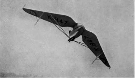
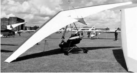
This type has had followers from the very early days of flying – and among birds from prehistoric times – and although the reasons for its adoption have changed somewhat, a common feature has been a large degree of sweepback, or even delta-shaped wings, so that although this type may appear to have no tail, the exact equivalent is found at its wing tips, the wings being, in fact, swept back so that the tip portion can fulfil the functions of the tail plane in the orthodox aeroplane. In fact, it is true to say that the ‘tail-less’ type has two tails instead of one! (Figs 5C and 5D).

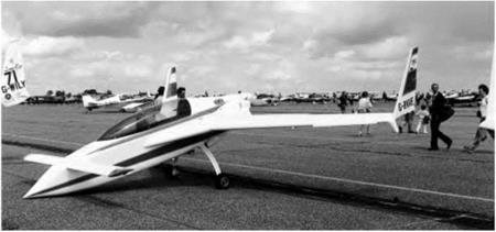
More unusual is the tail-first or canard configuration aeroplane. A most important historical example was the original Wright Flyer, which is generally accepted to have made the first controlled power-driven flight. Like many early ideas, the canard has recently made something of a come-back (Fig. 5E, over­leaf), and examples are now found for many types of aircraft, but particularly for missiles and highly manoeuvrable fighters such as the Eurofighter Typhoon. A tail in front can hardly be called a tail, and this surface is com­monly known now as the foreplane.

L (tail)

'Tail-less' and 'tail-first' aeroplanes

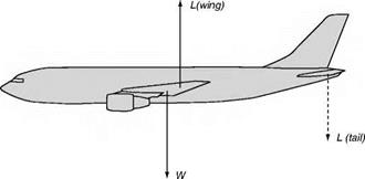
Fig 5.3 The pilot can adjust the tail lift so that the resultant moment is zero and the aircraft is trimmed. The tail lift can be either upwards or downwards

'Tail-less' and 'tail-first' aeroplanes

Fig 5C Tail-less – old type (By courtesy of Flight)

The Westland Hill Pterodactyl.

'Tail-less' and 'tail-first' aeroplanes

Fig 5D Tail-less – new type

This popular form of powered microlight aircraft has been derived from hang-glider technology.

'Tail-less' and 'tail-first' aeroplanes

Fig 5E Tail-first

Apart from the canard layout, the Rutan Vari-Eze shows many unusual features such as a pusher propeller, composite construction, and a nosewheel that can be retracted in flight or when parked.

The tail plane and other horizontal control surfaces

The traditional method of ensuring that the aircraft can be trimmed to give no resultant moment is to provide the aircraft with an auxiliary lifting surface

The tail plane and other horizontal control surfaces

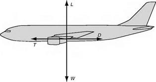
Fig 5.1 Forces acting through a single point. This arrangement is not generally practical, as the line of action of the lift tends to move around with the angle of attack

The tail plane and other horizontal control surfaces

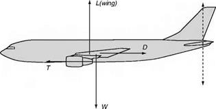
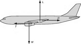
Fig 5.2 Moment due to lift and weight balanced by moment due to drag and thrust

The tail plane and other horizontal control surfaces

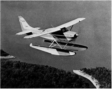
Fig 5B Floatplane

(By courtesy of Cessna Aircraft Company, USA)

called a tail plane. The lift of the tail plane can be regulated by the pilot, and thus he can adjust the moment that it applies. Fig. 5.3 (overleaf) shows how this works. The tail plane can produce lift in either the positive (upward) or nega­tive (downward sense) in order to produce the required moment for trim. To change the tail plane lift, either the whole surface can be pivoted, or the rear part of the surface (the elevator) can be hinged up or down. In practice, for small adjustments to the trim, it is common practice to provide a very small hinged surface or ‘trim tab’ in addition to the main elevator, as described later.

Nowadays, there are many types of horizontal control surface, and sometimes even the engine exhaust direction can be altered to provide a trim control.

Difficulties in balancing the four forces

First, the lift. The lift will act through the centre of pressure, which will depend on the position of the wings; so the designer must be careful to place the planes in the correct position along the fuselage. But the problem is complicated by the fact that a change in the angle of attack means a movement of the lift, and usually in the unstable direction; if the angle of attack is increased the pitching moment about the centre of gravity will become more nose-up, and tend to increase the angle even further.

Secondly, the weight. This will act through the centre of gravity, which in turn will depend on the weight and position of every individual part of the aeroplane and the loads that it carries. Here alone is sufficient problem, but again there is a possibility of movement of the centre of gravity during flight caused, for instance, by consumption of fuel, dropping of bombs or movement of passengers. In the Concorde, fuel was actually moved from one tank to another to adjust the position of the centre of gravity.

Thirdly, the thrust. Here the problem is easier. The line of thrust is settled by the position of the propeller shaft or centre line of the jet, which in turn depend on the position of the engine or engines. In this matter the designer has little choice, but has to consider such problems as keeping the propeller clear of the ground and giving the pilot a clear view ahead; new problems arise too when the thrust can be deflected as in certain modern types.

Lastly, the drag. This is, perhaps, the most difficult of all. The total drag is composed of the drag of all the separate parts, and the designer must either estimate the drag of each part separately, and so find the total drag and its line of action, or must rely on wind tunnel experiments on a model or computed predictions; and even when the line of drag has been found it too will be liable to change at different angles of attack.

Arranging the forces

For steady flight along a straight line, whether level or not, it is not only necessary to balance the four forces so that they produce no resultant force; their lines of action must also be arranged so that they produce no resultant moment, otherwise the aircraft will rotate either nose-up or nose-down. When there is no resultant moment, the aircraft is said to be trimmed. Mathematically, if the sum of the moments is M, then the condition for trim is that M=0.

One way to achieve this would be to arrange that all of the forces act through a single point, as in Fig. 5.1. However this is not generally practical, as there are many factors that tend to alter the line of action, apart from those already stated. For example, lowering the undercarriage tends to shift the line of the resultant drag down, and on the floatplane variant of a light aircraft illustrated in Fig. 5B the position of the drag resultant would be very much lower than for the original floatless design.

It is possible to balance the moment produced by the drag and thrust being out of line, by arranging the lift and weight forces to be out of line by an amount that causes them to exactly produce the necessary balancing moment, as in Fig 5.2. However, because of the way that the lines of action of the forces tend to change according to aircraft attitude, fuel weight etc., there is no simple design solution to ensure that the resultant moment will always be zero. As described below, some active involvement of the pilot is required in order to keep the aircraft trimmed.

Conditions of equilibrium

Now, under what conditions will these four forces balance the aeroplane? That is to say, keep it travelling at a steady height at uniform velocity in a fixed direction, a state of affairs which, in the language of mechanics, is known as equilibrium. It is sometimes hard to convince a traveller by air that he may travel at 200 m/s and yet be in a state of equilibrium; equilibrium simply means that the existing state of affairs is remaining unchanged; in other words, that the aeroplane is obeying Newton’s First Taw of Motion.

In order to do this the forces acting on it must be balanced – the lift must be equal to the weight (this condition will keep the aeroplane at a constant height); and the thrust must be equal to the drag (this condition will keep the aeroplane moving at the same steady velocity).

The idea is often prevalent that the lift must be greater than the weight, or, as it is often expressed, the lift must ‘overcome’ the weight; and when it comes to the question of thrust and drag the author has known students dismiss the idea that the thrust need only be equal to the drag as ‘contrary to common sense’.

There still remains a third condition for equilibrium. In order to maintain straight and even flight, we must prevent the aeroplane from rotating, and this depends not only on the magnitudes of the four forces, but also on the pos­itions at which they act. If the centre of pressure is behind the centre of gravity, the nose will tend to drop and the tail to rise, and vice versa if the centre of pressure is in front of the centre of gravity. But we are also concerned with the lines of action of the thrust and drag, for if the line of thrust is high and the line of drag is low, these two forces also will tend to make the nose drop. Such tendencies could be prevented by the pilot using his controls, but it is the aim of the designer to make an aeroplane which will in the words of the pilot, fly ‘hands off’. Therefore he must see that the forces act in the right places.

The four forces

Now, what are the forces which keep the aeroplane in its state of steady level flight? First the lift, which will be vertically upwards since the direction of motion is horizontal. This we have created with the express object of keeping the aeroplane in the air by opposing the force of gravity, namely, the weight. But we can only produce lift if the aeroplane is moved forward and for this we need the thrust provided by the propeller or jets. We also know that the forward motion will be opposed by the drag.

The aeroplane, therefore, can be said to be under the influence of four main forces – 1. The Tift, L, acting vertically upwards through the Centre of Pressure.

The four forces

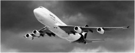
Fig 5A Long haul, large capacity

This Boeing 747-400 ‘Jumbo’ has 350 seats, and a range of 13 528 km that could take it from Europe to Australia non-stop.

2. The Weight of the aeroplane, W, acting vertically downwards through the Centre of Gravity.

3. The Thrust of the engine, T, pulling horizontally forwards.

4. The Drag, D, acting horizontally backwards.

Just as for certain purposes it is convenient to consider all the weight as acting through one point, called the centre of gravity, or all the lift as acting at the centre of pressure, so we may imagine the resultant of all the drag acting at one point which, for convenience, we will call the centre of drag. Its actual position depends on the relative resistance of different parts of the aeroplane.

Swing on take-off

Introduction

The flight of an aeroplane may be considered as consisting of various stages. First, the take-off, during which the aircraft is transferred from one medium to another; then the climb, during which the pilot gains the height at which the level part of the flight will be made; then a period of this steady flight at a con­stant height, interrupted in certain cases by periods of manoeuvres, or aerobatics; the approach back towards the earth; and finally the landing.

On long distance flights the main portion may consist of a long slow steady climb, which is more economical than maintaining the same height as fuel is consumed, and the weight of the aircraft is reduced, and so it is often only during a small portion of each flight that the aeroplane may be considered as travelling in straight and level flight at uniform velocity (Fig. 5A, overleaf).

There is often a tendency for an aeroplane to swing to one side during the take-off run. This must be due to some asymmetric feature of the aircraft, and it is an interesting problem to try to track down the real villain that is causing the swing.

The pilot should be the first suspect. He himself is not symmetrical, he may be right-handed (or left-handed), he probably looks out on one side of the aeroplane and may even sit on one side. Certain it is that some aircraft which have swung violently when the pilot has tried to keep them straight have gone as straight as a die when left to themselves!

The second and main suspect is undoubtedly the propeller. But which of its asymmetric effects is the chief cause of swing in any particular aircraft is not so easy to determine. If the propeller rotates clockwise, the torque reaction will be anti-clockwise, the left-hand wheel will be pressed on the ground and the extra friction should tend to yaw the aircraft to the left. But let us not forget that the torque reaction may be compensated and, in that case, the behaviour of the aeroplane will depend on how it is compensated.

The slipstream – assuming the same clockwise propeller – will itself rotate clockwise and will probably strike the fin and rudder on the left-hand side, again tending to yaw the aircraft to the left. But the slipstream too may be compensated.

The gyroscopic effect will only come in when the tail is being raised. Again the tendency will be to swing to the left if the propeller rotates clockwise. Try it with the bicycle wheel.

Apart from the compensating devices already mentioned the tendency to swing can be largely, if not entirely, eliminated by opposite rotating propellers on multi-engined aircraft (Fig. 4K), by contra-rotating propellers on single- engined aircraft and by jet propulsion or rocket propulsion instead of propellers.

Contra-rotating propellers not only give the greater blade area, or solidity, that is required to absorb large power, but they eliminate or very nearly elimi­nate all the asymmetrical effects of slipstream, propeller torque, and gyroscopic action. It is curious that the average pilot hardly realised the existence of these asymmetrical effects – until he lost them. Pilots who flew behind contra­rotating propellers for the first time reported that the aircraft was easy to handle and nice to fly. This is hardly surprising; what perhaps is surprising is that the previous ill-effects of one-way rotation had been so little noticed. The second propeller straightens the slipstream created by the first and so causes a straight high-speed flow of air over wings and tail; this improves the control and there is little or no resultant torque tending to roll the aircraft in one direc­tion, and therefore no need to counteract such tendency; the gyroscopic effects are also neutralised. All this means that there should be no tendency to swing to one side during take-off, no roll or yaw if the throttle is suddenly opened or closed, no difference in aileron or rudder trim, whether the engine is on or off – in short, the aircraft should be easy to handle and nice to fly.

Can you answer these?

Some simple questions about thrust and propellers –

1. What is a ramjet?

2. What is meant by the blade angle of a propeller, and why does this angle decrease from boss to tip?

3. Distinguish between the ‘advance per revolution’, the ‘geometric pitch’ and the ‘experimental pitch’ of a propeller.

4. What is slip?

5. What are the advantages of a variable-pitch propeller?

6. Why is the tip speed an important factor in propeller design?

7. Why is solidity important, and how can it be increased?

8. What methods of propulsion can be used outside the earth’s atmosphere?

For solutions see Appendix 5.

Turn to Appendix 3 for a few simple numerical examples on thrust.

The slipstream

The propeller produces thrust by forcing the air backwards, and the resultant stream of air which flows over the fuselage, tail units, and other parts of the aeroplane is called the slipstream.

The extent of the slipstream may be taken roughly as being that of a cylinder of the same diameter as the propeller. Actually there is a slight con­traction of the diameter a short distance behind the propeller.

The velocity of the slipstream is greater than that at which the aeroplane is travelling through the air; the increase in velocity may be as much as 100 per cent, or even more, at the stalling speed of the aeroplane. This means that the

The slipstream

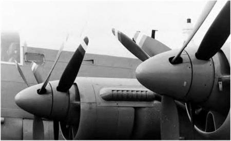
Fig 4K Contra-rotating propellers

Four sets of these six-bladed contra-rotating propellers were employed to propel the old Shackleton patrol aircraft. The noise inside the fuselage, which had no padding or sound absorption material, made the long duration flights decidedly arduous for the crew.

velocity of the air flowing over all those parts in the slipstream is twice that of the airflow over the other parts, and so the drag is four times as great as cor­responding parts outside the slipstream. At higher forward speeds the difference is not as great, being only about 50 per cent at normal speeds, and as little as 10 per cent at high speeds. The extra velocity of the slipstream may be beneficial in providing more effective control for rudder and elevators, especially when the aeroplane is travelling slowly through the air, e. g. when taxying, or taking off, or flying near the stalling speed. With jet propulsion, however, it is not advisable for the hot jet to strike the tail plane which, in con­sequence, is often set very high (Fig. 5F).

In addition to increased velocity, the propeller imparts a rotary motion to the slipstream in the same direction as its own rotation; so it will strike one side only of such surfaces as the fin, and so may have considerable effects on the directional and lateral balance of the aeroplane. If these effects are com­pensated for in normal flight – e. g. by offsetting the fin so that it does not lie directly fore and aft – then the balance will be upset when the engine stops and the slipstream ceases to exert its influence.

Gyroscopic effect

The rotating mass of the propeller or the compressor in the case of a jet engine may cause a slight gyroscopic effect. A rotating body tends to resist any change in its plane of rotation, and if such change does take place there is superim­posed a tendency for the plane of rotation to change also in a direction at right angles to that in which it is forced. This can easily be illustrated with an ordi­nary bicycle wheel; if the wheel, while rapidly rotating, is held on a horizontal shaft and the holder attempts to keep the shaft horizontal while he turns, the shaft will either tilt upwards or downwards according to whether he turns with the opposite or the same sense of rotation as that of the wheel. Thus if the propeller rotates clockwise when viewed from the pilot’s cockpit (the usual method of denoting the rotation), the nose will tend to drop on a right-hand turn and the tail to drop on a left-hand turn. It is only in exceptional cases that this effect is really appreciable, although it used to be very marked in the days of rotary engines when the rotating mass was considerable.

Number and shape of blades

The propeller must be able to absorb the power given to it by the engine; that is to say, it must have a resisting torque to balance the engine torque, other­wise it will race, and both propeller and engine will become inefficient.

The climbing conditions are particularly difficult to satisfy since high power is being used at low forward speeds; and if we do satisfy these conditions – by any of the methods suggested below – it will be difficult to get efficiency in high-speed flight. Thus, the propeller becomes a compromise like so many things in an aeroplane.

The ability of the propeller to absorb power may be increased by –

1. Increasing the blade angle and thus the angle of attack of the blades.

2. Increasing the length of the blades, and thus the diameter of the propeller.

3. Increasing the revolutions per minute of the propeller.

4. Increasing the camber of the aerofoil section of which the blade is made.

5. Increasing the chord (or width) of the blades.

6. Increasing the number of blades.

With so many possibilities one might think that this was an easy problem to solve, but in reality it is one that has caused considerable difficulty. First, the blade angle should be such that the angle of attack is that giving maximum efficiency; there is, therefore, little point in trying to absorb more power if, in so doing, we lose efficiency. The second possibility is to increase the diameter, in other words, to increase the blade aspect ratio, but quite apart from the bogey of tip speed, with large propellers there is the problem of providing enough ground clearance. The third would mean high tip speed and conse­quent loss of efficiency. The fourth, as with aerofoils, would simply mean a less efficient section; it would seem, too, that we must face even thinner aerofoil sections to avoid loss of efficiency at high speed. So we are left with the last two, and fortunately they provide some hope. Either will result in an increase in what is called the solidity of the propeller. This really means the ratio between that part of the propeller disc which, when viewed from the front, is solid and the part which is just air. The greater the solidity, the greater the power that can be absorbed.

Of the two methods of increasing solidity, increase of chord and increase of number of blades, the former is the easier, the latter the more efficient. The so – called paddle blades are examples of the former method. But there is a limit to this, first, because the poor aspect ratio makes the blades less efficient.

So, all in all, an increase in the number of blades is the most attractive prop­osition, and that is why we saw, first, the two-blader (yes, there has been a one-blader! – but only one); then, in turn, three, four, five, and six blades; and we might have gone to eight – and ten-bladers had not jet propulsion come along at the critical time.

After four or, at the most, five blades, it becomes inconvenient to fit all the blades into one hub, and it is, in effect, necessary to have two propellers for each engine. If we are going to have two propellers, we may as well rotate them in opposite directions (Fig. 4K, overleaf) and so gain other advantages which will become more apparent when we have considered the effects of the propeller on the aeroplane.