Category MECHANICS. OF FLIGHT

Rocket propulsion

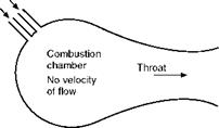
Rocket propulsion is also very straightforward in principle. As illustrated in Fig 4.3 (overleaf), in the simplest motors, fuel is burned in a combustion chamber, to create heat and a high pressure gas. The hot gases then flow out through the specially-shaped throat and outlet nozzle at high speed. The main difference between the rocket and other forms of propulsion is that air is not used as the oxidant in the burning process, and the gases that are emitted from the outlet are all derived from the fuels.

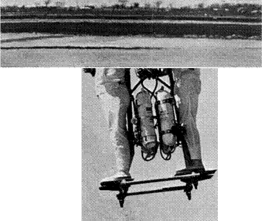
Apart from its use in some high speed research aircraft, and one highly dan­gerous German interceptor aircraft of Word War II (the Messerschmitt Me 163), the rocket is mainly used for missiles and spacecraft. The strange vehicle shown in Fig. 4D (overleaf), which used a rocket both for propulsion and lift, never developed into a practical means of transport.

Rocket motors come in two basic types, a solid fuel type, where the fuel and oxidiser are combined in a stable solid form, as in a simple firework, and a liquid propellant type, where two chemicals, one usually the fuel and the other a powerful oxidiser, are mixed together and burned in a combustion chamber.

Rocket propulsion

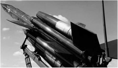
Fig 4C Ramjet propulsion

The ВАС Bloodhound missile used two ramjets: the large tubular shapes with silvery ends which can be seen above and below the body. The smaller tubes are solid-fuel rockets which were used to boost the missile to high speed; they were jettisoned once the ramjets had taken over.

Supply of fuels


Typical jet speed 2000 m/s


Rocket propulsion

Rocket propulsion

Fig 4.3 Principle of rocket propulsion

Fig 4D Rocket propulsion

(By courtesy of Bell Aerospace Division of Textron Inc, USA)

Flying the two-man Pogo from the rear platform is the rocket belt operator; on the front deck is the rocket technician.

Rocket motors have a very high thrust to weight ratio, and are essentially very simple. However they use fuel and oxidiser at a very high rate, and so have relatively short duration. The need to carry oxidiser as well as fuel means that the total weight of expendable chemicals carried is much higher than in engines that use air as the oxidant. Recently, engines have been developed which use air as the oxidant at low altitudes and pure rocket propulsion at high altitudes or in space.

Apart from the simple chemically fuelled rockets, several more advanced types have been developed. These include ones in which ionised particles or plasma is accelerated to very high speeds by electrostatic or electromagnetic forces. Some of these have been used on spacecraft, normally as low-thrust control jets.

The ramjet and scramjet

The ramjet engine will be mentioned here, because, although hardly ever used for aircraft, it is important for missiles and potentially important for the early stages of spacecraft flight. In principle, the ramjet is extremely simple, and, as

The ramjet and scramjet

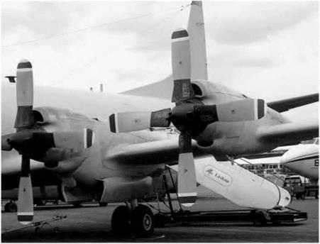
Fig 4B Turboprop propulsion

The Lockheed Orion with four turboprops. Note the huge wide-chord ‘paddle-blade’ propellers.

shown in Fig. 4.2, consists of nothing more than a duct or tube of a special shape which faces the airflow in a moving aircraft. It relies on the forward speed to collect and compress the air, the so-called ram effect described in the preceding section. The air thus compressed flows past, a source of heat, such as a jet of burning fuel, as in a jet engine. From this, the air gains energy, flowing out faster than it entered. As with the jet engine, the reaction to this increase in air flow speed and momentum is a thrust force, which pushes the engine forward. This simple engine has no moving parts and there is almost nothing to go wrong. The exhaust air jet does not need to drive a turbine, and can be used entirely for direct thrust production. It should be noted that the shape of the duct is important. You cannot make a ramjet by burning fuel in a simple constant-bore tube; all you would get from that would be drag and some hot air.

So if ramjets are so simple, why have they rarely been used on aircraft? The answer is that there is a major snag, and that is that they will only generate thrust efficiently at high speeds. In fact, they only start to become as efficient as a jet engine at several times the speed of sound. At zero forward speed they will not work at all, so any vehicle to be propelled by a ramjet must first be accelerated by some other type of engine or propulsion system. Ramjets have been used for missiles, as shown in Fig 4C. In this case, a simple rocket is used to propel the vehicle to a high speed, whereafter, the more efficient ramjet takes over. The rocket and ramjet combination thus gives a greater range than would be possible with the highly inefficient rocket engine alone. Ramjets have rarely been used on aircraft except for a few experimental types, but the SR71 ‘Blackbird’ spy-plane used a special engine which functioned as a turbojet engine at low speeds, and as a ramjet at high speeds.

Подпись: Intake Fuel Combustion diffuser spray chamber

The scramjet (supersonic combusting ramjet) works on the same principle as the ramjet, but in this case, the air flow in the engine is everywhere super­sonic. In very high speed hypersonic flight this is necessary, because the thermodynamic efficiency becomes too low if the air speed is reduced to less than the speed of sound anywhere in the engine. The problem is that in a supersonic flow, the flame produced by burning simple fuels simply blows out. One solution is to use two fuels that react violently as they are mixed. This may be acceptable for military aircraft and missiles, but fare-paying passengers

Fig 4.2 Principle of the ramjet

might not relish the idea of sitting in an aircraft containing highly reactive fuels that must never meet except in the combustion chamber!

Turboprop and turboshaft engines

The turboprop engine is constructed in much the same way as the turbojet engine, but more of the available energy in the exhaust is used to drive the turbine. The extra power produced by the turbine is used to drive a propeller. Some thrust is produced by the exhaust jet, but this is only a relatively small proportion of the total. The advantage of the turboprop engine over the pure jet is that it is much more efficient. As we will see later, it is more efficient to produce thrust by giving a small increase in momentum to a large amount of air (as with a propeller), than to give a large increase in momentum to a small amount (as with a pure turbojet). However, as mentioned previously, pro­pellers produce serious problems at high speed. They are also noisy, and require high maintenance, and require the addition of a heavy gearbox to reduce the turbine speed, which can be up to 100 000 rpm or more, down to the few thousand rpm required for a propeller. They are normally used for relatively low-speed aircraft such as small airliners or heavy-lift transport types (Fig. 4B).

Instead of driving a propeller, the gas-turbine may be used to drive the rotor-blades of a helicopter, and in this application it is normally known as a turbo-shaft engine. Most military helicopters use turboshaft engines. Turboshaft engines are also used for purposes such as the production of aux­iliary electrical power.

Propulsion systems

This is a book on the mechanics of flight, and it would be out of place to go into the thermodynamics of propulsion systems, but we will give a brief description of the basic principles of the more important methods of propul­sion. The oldest system, the piston-engine and propeller, is still in common use for light aircraft, and involves a large number of mechanical parts. The pro­peller itself is, of course, an almost entirely aerodynamic device. In the ramjet and rocket, described later, there are few significant mechanical parts, apart from fuel pumps, and the entire system relies entirely on aerodynamic and thermodynamic principles. Between the two extremes there are the jet and tur­boprop engines which involve a combination of mechanical and aero-thermodynamic principles.

Turbojet propulsion

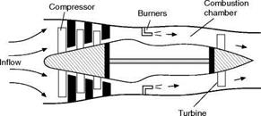
Nowadays, the most common form of aircraft engine is the turbojet, which is normally just referred to as the jet engine. The turbojet is in principle, a very simple form of propulsion unit based on the gas turbine engine. A basic version is shown schematically in Fig 4.1. Air enters at the front and its pressure and temperature are raised by the action of the compressor. Heat is added in the combustion chamber by burning fuel (usually kerosene), and the heated air leaves at high speed. Part of the energy that it has gained is used to drive a turbine, which in turn drives the compressor. The air leaves as a high­speed jet. As the speed of the air has increased, the momentum has increased, and the reaction to this momentum change is a thrust force pushing the engine forward. The intake faces forward, in flight, so the air is effectively “rammed” in. This so-called ram effect helps to compress the air, and as the forward speed increases, less and less work has to be done by the compressor, leaving more of the energy increase to be used to generate thrust, so the efficiency of the propulsion system improves.

Propulsion systems

Fig 4.1 Principle of the turbojet

Propulsion systems

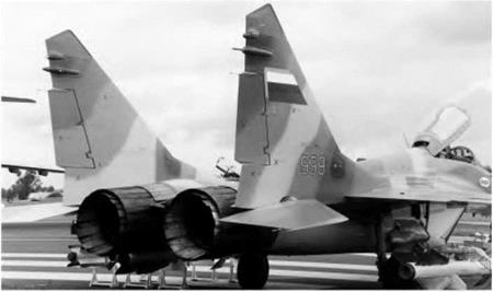
Fig 4A Turbojet propulsion

The hot end of a MiG-29. Two Tumansky R-33D low-bypass turbojet engines, each producing 81.4 kN thrust (with reheat). Note the complex variable area outlet nozzles.

The turbojet is much simpler than the “piston” engines that it has almost entirely displaced, and it has no reciprocating parts to wear and cause vibra­tions. Most importantly, it produces very much more thrust for a given weight at high speed. An added advantage is that it will work efficiently close to and beyond the speed of sound, where propellers cannot be used, as described later.

The simple type of jet engine shown in Fig. 4.1 has now largely been replaced by the more efficient high by-pass and fan-jet engines described later in this chapter.

Icing

All these mechanical devices are designed to vary the characteristics of an aerofoil according to our needs, but there is one important form of variable camber which is the work of nature and over which we have little control, namely the formation of ice. Brief mention has already been made of this problem in connection with laminar flow aerofoils, but the effects of icing may be far wider than this, affecting as they do, not only the wings, but many parts of the aircraft, the engine intakes and even the propeller. Icing conditions can arise in various conditions of atmospheric humidity and temperature, but they become worse at regions of low pressure such as on the upper surface of wings near the leading edge, and at engine intakes – just the places where any alter­ation of contour can be most serious. Apart from the effect on shape, the actual weight of accumulation of ice can be considerable and this alone has been the cause of accidents, as has also the breaking off of lumps of ice which may enter the engine or strike other parts of the aircraft.

Many methods both of prevention and cure have been used to combat the ice problem, and they may be divided into three main categories – mechanical methods (such as rubber overshoes alternately inflated and deflated) designed to break up the ice; heating methods (using the heat of the engines or separate heaters) designed to melt the ice on the leading edges of the wings, fins, engine intakes, etc.; and the use of special anti-icing fluid (about the only method suit­able for propellers where it is flung out from the hub). All these, necessary

though they may be, mean extra weight and complication, and some of them absorb part of the engine power.

Can you answer these?

If you understand aerofoils you have broken the back of the problems of flight

– so test yourself with the following questions.

1. How does the pressure distribution over an aerofoil change as we increase the angle of attack from negative values to beyond the stalling angle?

2. What is meant by the centre of pressure of an aerofoil?

3. Why is it more convenient to speak of the lift coefficient and drag coeffi­cient rather than the lift and drag of an aerofoil?

4. What is meant by the aerodynamic centre of an aerofoil section?

5. What do you understand by the stalling angle of an aerofoil? Why should one not talk about the stalling speed of an aerofoil?

6. What is aspect ratio and what is its significance?

For solutions see Appendix 5.

For numerical examples see Appendix 3.

Icing

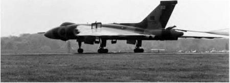
Fig 31 Speed brakes

Speed brakes on the wings of the last Vulcan bomber (now sadly retired). The cables of a braking parachute can also just be seen trailing from the rear.

Introduction

In Chapter 2 we made a study of drag – the force that tries to hold the aero­plane back. In this chapter we shall deal with thrust – the force that opposes drag and keeps the aeroplane going forward. In steady level flight the thrust must be equal to the drag, in order to accelerate the aeroplane it must be greater than the drag, and in climbing it must also be greater than the drag because it will have to support some proportion of the weight. The actual con­ditions of balance of the forces will be dealt with in the next chapter; it is sufficient at this stage to realise that we must provide the aeroplane with con­siderable thrust, and that the performance that we can achieve from the aeroplane will be largely dependent upon the amount of thrust that we can provide.

Once the aeroplane is clear of the ground, the only reasonable way of obtaining thrust is to push air or something else backwards and to rely on the reaction to push the aeroplane forwards. This is, in fact, what is done, and to save complication the same system is usually used while still on the ground. The precise physical process by which this reaction is produced and trans­mitted to the aircraft depends on the type of propulsion system used.

The thrust-provider, of whatever kind it may be, must be supplied with energy. This will usually be in the form of a fuel, which is fed into some kind of ‘engine’ where, in burning, its chemical energy is changed into thermal energy, which in turn is converted into the mechanical work done in propelling the aeroplane against the drag. Methods of providing thrust differ only in the way in which these various conversions are effected, and in the efficiency of the conversion, that is to say in the proportion of useful work got out to the energy supplied.

Flaps

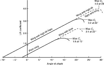
The history of flaps is longer, and just as varied, as that of slots. The plain or camber flap works on the same principle as an aileron or other control surface; it is truly a ‘variable camber’. Such flaps were used as early as the 1914-1918 war, and the original idea was the same as with slots, to decrease landing speed with flaps down, and retain maximum speed with flaps up. Their early use was almost exclusively for deck-landing purposes. It seemed at first as though the invention of slots, which followed a few years after that war, might sound the death-knell of flaps. Far from it – if anything it has been the other way round, for flaps have become a necessity on modern aircraft. Flaps, like slots, can increase lift – honours are about even in this respect so far as the plain (or camber) flap, or split flap is concerned. But these flaps can also increase drag – not, like slots, at high speed when it is not wanted, but at low speed when it is wanted. But the main difference between the effects of flaps and slots is shown in Fig. 3.33; from this it will be seen that whereas slots merely prolong the lift curve to higher values of the maximum lift coefficient, when the angle of attack of the main portion of the aerofoil is beyond the normal stalling angle, the high-lift type of flap increases the lift coefficient available throughout the whole range of angles of attack.

However it is no longer appropriate to compare the relative merits of slots and flaps because in modern aircraft it is usual to combine the two in some

form or other; and in this way to get the best of both devices (Fig. 3G). There is a large number of possible combinations, but Fig. 3.32 is an attempt to sum up the main varieties, and to describe the effect they have on the maximum lift coefficient, on the angle of the main aerofoil when maximum lift is obtained, why they improve the lift, what effects they have on the drag, how they affect the pitching moment, and so on.

From this figure it will be seen that the simpler flaps such as the camber flap, split flap and single slotted flap give a good increase in maximum lift coeffi­cient at a reasonable angle of attack of the main aerofoil, and therefore a reasonable attitude of the aeroplane for landing; they also increase drag which is an advantage in the approach and landing.

The more complicated types such as the Zap and Fowler flap, and the double – or treble-slotted flap, give an even greater increase in maximum lift coefficient, but still at a reasonable angle of attack; while the even more com­plicated combinations of slots and flaps give yet greater maximum lift coefficients, but usually at larger angles of attack, and of course at the expense of considerable complication (Fig. 3H, overleaf).

Blown and jet flaps are in a class of their own since they depend on power to produce the blowing, and this may be a serious disadvantage in the event of power failure. The true jet flap isn’t a flap at all, but simply an efflux of air, or a jet stream in the form of a sheet of air ejected under pressure at or near the trailing edge of the aerofoil. This helps to control the boundary layer, and if the sheet of air can be deflected the reaction of the jet will also contribute directly to the lift.

The Krueger and other types of nose flap are used mainly for increasing lift for landing and take-off on otherwise high-speed aerofoils.

Spoilers, air brakes, dive brakes, lift dumpers and suchlike are a special cat­egory in that their main purpose is to increase drag, or to destroy lift, or both; moreover, they need not necessarily be associated with the aerofoils (Fig. 31, overleaf). They are used for various purposes on different types of aircraft; to spoil the T/D ratio and so steepen the gliding angle on high-performance sailplanes and other ‘clean’ aircraft; to check the speed before turning or manoeuvring; to assist both lateral and longitudinal control; to ‘kill’ the lift and provide a quick pull-up after landing; and on really high-speed aircraft to prevent the speed from reaching some critical value as in a dive. They will be considered later as appropriate to their various functions.

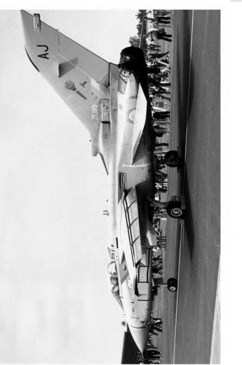
Fig 3G Flaps and slats (opposite)

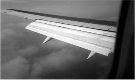
Double-slotted flaps and leading edge slats are used on the Tornado. Because the flaps extend across the entire span, there is no room for ailerons, instead, the slab tailplane surfaces can move differentially as well as collectively, and this ‘taileron’ serves both for roll and pitch control.

Flaps

Flaps

Fig 3H Multi-element slotted flaps

Three-element slotted Fowler-type flaps extend rearwards and down as this Boeing 737 prepares to land.

Slots

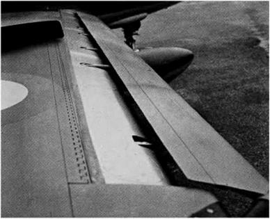
If a small auxiliary aerofoil, called a slat, is placed in front of the main aero­foil, with a suitable gap or slot in between the two (Fig. 3F, overleaf), the maximum lift coefficient of the aerofoil may be increased by as much as 60 per cent (Fig. 3.33, overleaf). Moreover the stalling angle may be increased from 15° to 22° or more, not always an advantage as we shall discover when we consider the problems of landing. An alternative to the separate slat, simpler but not so effective, is to cut one or more slots in the basic aerofoil itself, forming as it were a slotted wing.

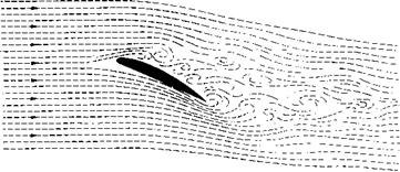
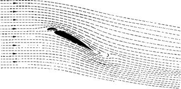
The reason behind these results is clearly shown in Fig. 3.34 (later). Stalling is caused by the breakdown of the steady streamline airflow. On a slotted wing the air flows through the gap in such a way as to keep the airflow smooth, fol­lowing the contour of the surface of the aerofoil, and continuing to provide lift until a much greater angle is reached. Numerous experiments confirm this con­clusion. It is, in effect, a form of boundary layer control as described earlier.

The extra lift enables us to obtain a lower landing or stalling speed, and this was the original idea. If the slots are permanently open, i. e. fixed slots, the extra drag at high speed is a disadvantage, so most slots in commercial use are

High-lift devices

Increase

of

maximum

lift

Angle of basic aerofoil at

max. lift

Remarks

Basic aerofoil

15°

Effects of all high-lift devices depend on shape of basic aerofoil.

Plain or camber flap

50%

12°

Increase camber. Much drag when fully lowered. Nose-down pitching moment.

Split flap

60%

14°

Increase camber. Even more drag than plain flap. Nose-down pitching moment.

Zap flap

90%

13°

Increase camber and wing area. Much drag. Nose-down pitching moment.

Slotted flap

65%

16°

Control of boundary layer. Increase camber. Stalling delayed. Not so much drag.

Double-slotted flap

70%

18°

Same as single-slotted flap only more so. Treble slots sometimes used.

V

Fowler flap

90%

15°

Increase camber and wing area. Best flaps for lift. Complicated mechanism. Nose-down pitching moment.

Fig 3.32 High lift devices

Note. Since the effects of these devices depend upon the shape of the basic aerofoil, and the exact design of the devices themselves, the values given can only be considered as approximations. To simplify the diagram the aerofoils and the flaps have been set at small angles, and not at the angles giving maximum lift.

High-lift devices

Increase

of

maximum

lift

Angle of basic aerofoil at

max. lift

Remarks

~1

Double-slotted Fowler flap

100%

20°

Same as Fowler flap only more so. Treble slots sometimes used.

Krueger flap

50%

25°

Nose-flap hinging about leading edge. Reduces lift at small deflections. Nose-up pitching moment.

Slotted wing

40%

20°

Controls boundary layer. Slight extra drag at high speeds.

Fixed slat

50%

20°

Controls boundary layer. Extra drag at high speeds. Nose-up pitching moment.

Movable slat

60%

22°

Controls boundary layer. Increases camber and area. Greater angles of attack. Nose-up pitching moment.

Slat and slotted flap

75%

25°

More control of boundary layer. Increased camber and area. Pitching moment can be neutralised.

Slat and

double-slotted Fowler flap

120%

28°

Complicated mechanisms. The best combination for lift; treble slots may be used. Pitching moment can be neutralised.

Blown flap

80%

16°

Effect depends very much on details of arrangement.

Jet flap

60%

?

Depends even more on angle and velocity of jet.

Slots

Fig 3F Leading edge slat and slot (By courtesy of Fiat Aviazione, Torino, Italy)


Fig 3.33 Effect of flaps and slots on maximum lift coefficient and stalling angle


Slots

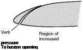
controlled slots, that is to say, the slat is moved backwards and forwards by a control mechanism; and so can be closed for high-speed flight and opened for low speeds. In the early days experiments were made which revealed that, if left to itself, the slat would move forward of its own accord. So automatic slots came into their own; in these the slat is moved by the action of air pressure, i. e. by making use of that forward and upward suction near the leading edge. Figure 3.35 shows how the force on the slat inclines forward as the stalling angle is reached. The opening of the slot may be delayed or hastened by ‘vents’ at the trailing or leading edge of the slat respectively (Fig. 3.36), and there may be some kind of spring or tensioning device to prevent juddering, which may be otherwise likely to occur. It is also important to ensure that the slots open on both wings at the same time!

Before leaving the subject of slots – for the time being, at any rate – there are a couple of interesting points which may be worth mentioning. Firstly, the value of the slot in maintaining a smooth airflow over the top surface of the wing can be materially enhanced by blowing air through the gap between slat and wing; this may be called a blown slot. Secondly, what might be called the ‘slot idea’ may be extended to other parts of the aircraft. Specially shaped cowlings can be used to smooth the airflow over an engine, and fillets may be used at exposed joints, and other awkward places, to prevent the airflow sep­arating.

Slots

Slots

Slots

Подпись: Region of decreased Подпись: pressure To hasten opening

Fig 3.35 Direction of force on slat at varying angles of attack

To delay opening

Fig 3.36 Effect of vents on opening of automatic slots

Variable camber

Many attempts have been made to provide aerofoils with some kind of vari­able camber so that the pilot might be able to alter his aerofoil from a high-lift type to a high-speed type at will. Owing to the tremendous advantage to be gained by such a device, it is not surprising to find that much ingenuity has been expended, many patents have been taken out, and it is not easy to compare the rival merits of the various slots, flaps, slotted flaps, and so on. Figure 3.32 (overleaf) shows some of the devices with the increase in maximum lift claimed for each, but we must not take these figures as the only guide to the usefulness or otherwise of each device, because there are other points to be considered besides maximum lift. For instance, we may want a good ratio of maximum CL to minimum CD (which indicates a good speed range), or an increase in drag as well as lift, the flaps acting as an air brake, which may be useful in increasing the gliding angle (explained later). Another important consideration is the simplicity of the device; anything which needs complicated operating mechanism will probably mean more weight, more controls for the pilot to work, something more to go wrong.

Flaps and slots

Although there is a large variety of high-lift devices nearly all of them can be classed as either slots or flaps – or a combination of the two (Fig. 3.32).

Slots may be subdivided into –

(a) Fixed slots.

(b) Controlled slots.

(c) Automatic slots.

(d) Blown slots.

Flaps may be subdivided into –

(a) Camber flaps.

(b) Split flaps.

(c) Slotted flaps.

(d) Lift flaps.

(e) Blown flaps.

(/) Jet flaps.

(g) Nose flaps.

(b) Spoilers.

(/) Lift dumpers.

(/) Air brakes.

We can also classify the effects of both slots and flaps on the characteristics of an aerofoil by saying that their use may cause one or more of the following –

(a) Increase of Lift.

(b) Increase of Drag.

(c) Change of Stalling Angle.

(d) Decrease of Lift.

(e) Change of Trim.

Taper and shape of wing tips

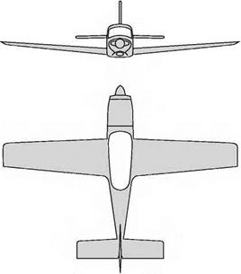
In addition to changes of aspect ratio, the plan form of the wing may be tapered from centre to wing tip; this is often accompanied by a taper in the depth of the aerofoil section (Fig. 3.31) and also by a ‘wash-out’, or decrease of angle of incidence, towards the wing tip – sometimes too a different aero­foil section is used near the tips. The tapered wing has advantages both from the structural and aerodynamic points of view. This is a feature in which we were slow to accept the teachings of nature, for the wings of most birds have a decided taper. Where the chord is not constant along the span, the numer­ical value of the aspect ratio is usually taken as the fraction (span/mean chord), or span2/area.

Taper in plan form means a sweepback of the leading edge, or a sweepfor – ward of the trailing edge, or both. Considerable sweepback of the whole wing

Taper and shape of wing tips

is sometimes used, but this is usually more for consideration of stability or for very high-speed flight, and discussion of the problem from these points of view is deferred to later chapters.

Circulation

An interesting way of thinking about the airflow over wings and wing-tip vor­tices is the theory of circulation. The fact that the air is speeded up over the upper surface, and slowed down on the under surface of a wing, can be con­sidered as a circulation round the wing superimposed upon the general speed of the airflow (this does not mean that particles of air actually travel round the wing). This circulation is, in effect, the cause of lift. If we now consider this circulation as slipping off each wing tip, and continuing downstream, we have the wing-tip vortices; and they rotate, as already established, downwards behind the wing and upwards outside the wing tips.

But this is not all. When the wing starts to move, or when the lift is increased, the wing sheds and leaves behind a vortex rotating in the opposite direction to the circulation round the wing – sometimes called the starting vortex – so there is a complete system of vortices, round the wing, then the wing-tip vortices, and finally the starting vortex. The wing-tip vortices and the starting vortex are gradually damped out with time – owing to viscosity – but the exertion of engine power (which ultimately is what creates the vortices, and so the lift and induced drag) keeps renewing the circulation round the wing, and the wing-tip vortices which result from it.

This is not just a theory; the flow over the wing can be clearly seen in experiments, as can the wing-tip vortices, while the starting vortex is easily demonstrated by starting to move a model wing, or even one’s hand, through water. But perhaps the most extraordinary example of the reality of the effect of aspect ratio on circulation and wing-tip vortices is that by clever forma­tion flying of say three or five aircraft, with the centre one leading, and the outer ones with their wing tips just behind the opposite wing tips of the

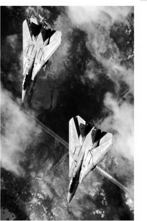
Fig3E Low aspect ratio (opposite)

(By courtesy of the Grumman Corporation, USA)

For high-speed flight, the wings of the FI4 are swung back producing an aspect ratio of less than 1. For low-speed flight they can be swung forward giving a higher aspect ratio.

Circulation

leading aircraft, it is possible to achieve something of the same result (which is illustrated in flying for maximum range) as with an aircraft of three or five times the span! This is hardly a practical proposition for flying across the Atlantic, but it has been illustrated by careful experiment, and geese and other birds used the technique long before we discovered it!