Category MECHANICS. OF FLIGHT

Variable pitch

For low-speed aeroplanes the thrust of a fixed-pitch propeller is usually found to be greatest when there is no forward speed, i. e. when the aeroplane is sta­tionary on the ground. The thrust developed under these conditions is called the static thrust, and its large value is very useful since it serves to give the aeroplane a good acceleration when starting from rest and thus reduces the run required for taking off. But in high-speed aircraft a fixed-pitch propeller designed for maximum speed would have such a large pitch, and, therefore, such steep pitch angles, that some portions of the blades would strike the air at angles of as much as 70° or more when there is no forward speed, the efficiency and static thrust would be very poor, and great difficulty would be experienced in taking off. The only remedy is variable pitch.

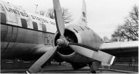
This requirement led to the development of the so-called constant-speed propeller (Fig. 4J) in which the pitch is automatically adjusted so that the pro­peller revolves at a given rate decided by the pilot, and remains at that rate irrespective of throttle opening or manoeuvres of the aeroplane. Thus engine and propeller can work at high efficiency irrespective of conditions, such as take-off, climb, maximum speed, altitude, and so on.

Variable pitch

Fig 41 Constant-speed propeller

A classic constant-speed propeller design. The hydraulically-actuated speed control unit is housed in the small domed unit on the front of the hub.

It has already been stated that there are problems common to propeller and helicopter blades, and one of these is that of variable pitch, which in helicop­ters is a virtual necessity as a means of control.

An extension of the idea of variable pitch leads to a propeller with the pitch variable not only over the range of blade angles that will be required for normal conditions of flight but beyond these angles in both directions.

If the blade can be turned beyond the normal fully-coarse position until the chord lies along the direction of flight, thus offering the minimum resistance, the propeller is said to be feathered. This condition is very useful on a multi­engined aircraft for reducing the drag of the propeller on an engine that is out of action. It has another advantage too in that it is a convenient method of stopping the propeller and so preventing it from ‘windmilling’; this reduces the risk of further damage to an engine that is already damaged.

The turning of the blade beyond the fully-fine position makes the propeller into an effective air brake; it has exactly the opposite effect to feathering by causing the maximum drag, which occurs when the blade angle is approxi­mately 2° or 3°.

If the blade angle is still further reduced, i. e. to negative angles, then instead of allowing the blades to windmill, we can run the engine and produce negative thrust or drag. This produces an excellent brake for use in slowing up the aero­plane after landing since it gives a high negative thrust at low forward speeds.

Tip speed

The power developed by a piston engine depends upon the pressures attained during combustion in the cylinders and on the revolutions per minute. The greatest power in most engines is developed at a fairly high number of revolu­tions per minute; and if the propeller rotates at the same speed as the engine crankshaft, the tip speed of the propeller blades is liable to approach or exceed the speed of sound (about 340 m/s in air at ground level, and less at higher alti­tudes). This causes compressibility effects (see Chapter 11), which, in turn, mean an increase in torque and decrease in thrust; in other words, a loss of efficiency. It is clearly of little purpose to design an engine to give high power, if at such power the propeller is to become less efficient and so transfer a lower proportion of the engine power to the aircraft. In the early stages of compress­ibility some improvement can be effected by changing the blade section near the tip to a thin laminar-flow type and by washing out the blade angle slightly; if this is done the loss is not serious so long as the actual speed of the tip does not exceed the speed of sound. As a further help a reduction gear is often intro­duced between the engine crankshaft and the propeller; the reduction is not usually very large, perhaps 0.7 or 0.8 to 1, but is just sufficient to reduce the tip speed to a reasonable margin below the speed of sound.

The tip speed, of course, depends not only on the revolutions per minute, but also on the forward speed of the aeroplane and the diameter of the pro­peller. The high forward speed of modern aeroplanes is such that it is becoming very difficult to keep the tip speed down below the speed of sound, and it would seem that at forward speeds of 350 knots or more some loss in efficiency must be accepted. At 430 knots the loss in efficiency is serious and has spread to a larger proportion of the propeller blades so that it affects not only the tips but what should be the most efficient sections. At this stage there is nothing for it but for the propeller to retire gracefully and hand over supremacy to jet propulsion.

A further objection to high tip speed is that the noise caused by the pro­peller (incidentally a large proportion of the total noise) is much intensified, especially in the plane in which the propeller is rotating. This can be annoying both outside and inside the aircraft, and in severe cases, structural damage can result.

Efficiency

Now the efficiency of a propeller is the ratio of the useful work given out by the propeller to the work put into it by the engine. Mechanical work done is measured by the force multiplied by the distance moved, and so when either the force or the distance is zero, the useful work done is zero, and the efficiency nil. Thus when the propeller moves forward in each revolution a distance equal to the experimental pitch, the fact that there is no thrust means that there is no efficiency. Also, when there is no forward speed, there is no distance moved, no work done and therefore no efficiency. Between these two extremes are the normal conditions of flight.

It might be thought that the object of the propeller is to give the maximum thrust (T) with the minimum torque (Q), i. e. to give the maximum T/Q ratio. However, Figs 4.6 and 4.7 show that in order to get a high value of T/Q, two things are required – a high value of L/D and the optimum helix angle, which is theoretically around 45 degrees. The high value of T/D is fairly easy, and is an old problem; what is needed is a good aerofoil section, set at near the correct small angle to the relative air flow, and this means twisting the blade, as already explained.

The provision of the optimum helix angle is more difficult, as this would require matching the rotational speed to the forward speed. In practice, this is impractical, and the propeller is normally run at near constant speed, as described later. In any case, the optimum helix angle can only be obtained at one position along the blade, since the blade is twisted. However, the tip of the propeller is moving faster than the inboard sections, and thus tends to produce a high proportion of the thrust, so it is the angle of the tip that is most important. With fixed pitch propellers, a compromise on the pitch angle has to be made between high efficiency cruising, and high thrust for take-off.

Under conditions of maximum efficiency the advance per revolution is usually considerably less than the experimental pitch. The experimental pitch is sometimes called the ideal pitch, while the advance per revolution is the actual practical pitch. The difference between the two is called the slip, and is usually expressed as a percentage.

The calculation of propeller efficiency is quite straightforward. For example, if the total drag of an aeroplane at 65 m/s is 4.22 kN and the power developed by the engine when the aeroplane is flying at this speed is 336 kW, then –

Work given to propeller per second = 336 000 joules

Work done by propeller per second = 4220 X 65

= 274 300 joules

So efficiency of the propeller = Work got out/Work put in X 100 per cent

= (274 300/336 000) X 100 per cent

= 81.6 per cent

This represents the approximate value of the efficiency obtainable from a good propeller, although in some instances it may rise as high as 85 or even 90 per cent. The best efficiency is obtained when the slip is of the order of 30 per cent.

For those who prefer to examine this question in terms of mathematical symbols the efficiency of a propeller can be deduced as follows –

Tet v = forward velocity in m/s

T = thrust of propeller in newtons n = revolutions per second of engine Q = torque exerted by engine in N-m

Work done by thrust T at v metres per second = Tv joules per second, or watts

Work given by engine = 2nQ joules per rev

= 2miQ joules per second, or watts Efficiency of propeller = (Tv/2imQ) X 100 per cent

Pitch of a propeller

This quantity, p, is called the geometric pitch, since it depends only on the geo­metric dimensions and not on the performance of the propeller. The value of the geometric pitch of a fixed-pitch propeller may vary from about 1 metre for a slow type of aeroplane to the 5 or 6 metres that was used on Schneider Trophy and other racing aircraft (Fig. 41).

Pitch of a propeller

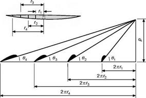
Fig 4.11 Geometric pitch

Pitch of a propeller

Fig 41 Fixed pitch propeller

(By courtesy of what was the Fairey Aviation Co Ltd)

Two-blader with very large pitch angle, as used in the Schneider Trophy contest, 1931.

The designer of a propeller may find it convenient to consider the pitch from a different viewpoint. When the advance per revolution reaches a certain value, the thrust becomes zero, the reason being that the angle of attack of each part of the blade has become so small that the aerofoil section of the blade provides no thrust. (Notice how this corresponds to the small negative angle at which an aerofoil ceases to give lift.) The experimental mean pitch is defined as the distance the propeller will move forward in one revolution when it is giving no thrust.

Advance per revolution

In a propeller, the blade angle at each section is greater than the helix angle and, what is more important, the distance moved forward in one revolution (called the advance per revolution) is not by any means a fixed quantity, as it depends entirely on the forward speed of the aeroplane.

Advance per revolutionDirection of motion of aeroplane
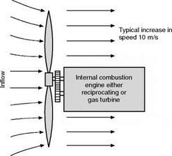
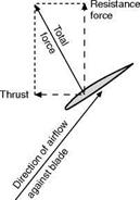
Fig 4.7 Motion of a section of a propeller blade Showing resolution of total force into thrust and resistance

Подпись: / ■N /  IS Подпись: -л -X Подпись: 7 / is"
Подпись: 71- Advance per revolution
Подпись: yf-

Helical path of A

Helical path of В

Advance

per revolution

Fig 4.8 Helical paths travelled by various sections of propeller blade

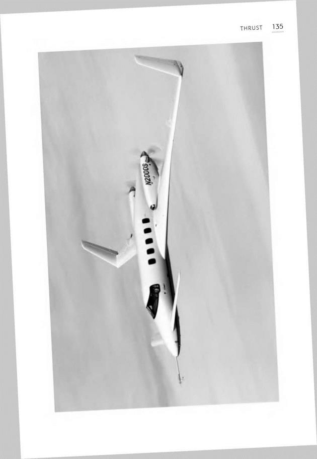
Fig 4G Pusher – new type (opposite)

(By courtesy of the Beech Aircraft Corporation, USA)

The Beech Starship. Twin pusher turboprop with many other advanced features including tail-first ‘canard’ configuration.

Advance per revolution

Advance per revolution

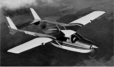
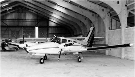
Fig 4H Pusher and tractor

(By courtesy of Cessna Aircraft Company, USA)

Unique 4/6 seater with two tandem horizontally opposed air-cooled engines, each driving a 2-blade feathering constant-speed propeller.


Advance per revolution

Fig 4.10 Blade angle


Advance per revolution

For instance, if an aeroplane is flying at 100 m/s and the propeller is making 1200 rpm – i. e. 20 revs per second – then the advance per revolution will be 100/20 = 5 metres. But the same aeroplane may fly at 80 m/s, with the same revolutions of the propeller, and the advance per revolution will be only 4 metres; while when the engine is run up on the ground and there is no forward motion, the advance per revolution will obviously be 0.

Considering first a fixed-pitch propeller, if the angle of a blade section at a radius of r metres is 0°, and if this particular blade section were to move par­allel to its chord – i. e. so that its angle of attack was 0° – while at the same time it made one complete revolution, then the distance travelled forward, p metres, would be a definite quantity and would correspond to the pitch of an ordinary screw, the relation p = 2кг tan в being true. This is best seen graph­ically by setting off the blade angle в from the distance 2кг drawn horizontally, p being the vertical height. If the same operation is carried out at different dis­tances from the axis of the propeller (Fig. 4.11), it will be found that the value of p is practically the same for all sections of the blade since as the radius r increases there is a corresponding decrease in the blade angle в, and 2кг tan в remains constant.

Helix angle and blade angle

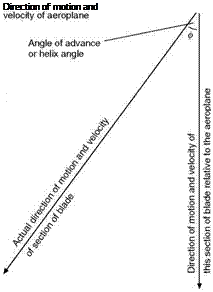
Why is the theory of the propeller more involved than that of the aerofoil? Chiefly because the local direction of motion of the blade is along a helix rather than a straight line, and, what is more, every section of the propeller blade travels on a different helix (Fig. 4.8, overleaf). The angle (<f>) between the resultant direction of the airflow and the plane of rotation (Fig. 4.6) is called the angle of advance or helix angle, and it is a different angle at each section of the blade. The sections near the tip move on a helix of much greater diam­eter, and they also move at a much greater velocity than those near the boss.

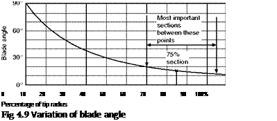
Since all the sections must be set at a small extra angle to give the angle of attack, and since for maximum efficiency this extra angle should be approxi­mately the same at all parts of the blade, it is clear that the blade angle, or pitch angle, must vary like the helix angle from boss to tip. Figure 4.9 (later) shows a typical variation of blade angle.

Подпись: Direction of motion and
Helix angle and blade angle

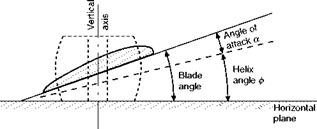
The blade angle is best defined as the angle which the chord of the propeller section at any particular place makes with the horizontal plane when the pro-

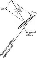
Fig 4.6 Motion of a section of propeller blade Showing resolution of total force into lift and drag

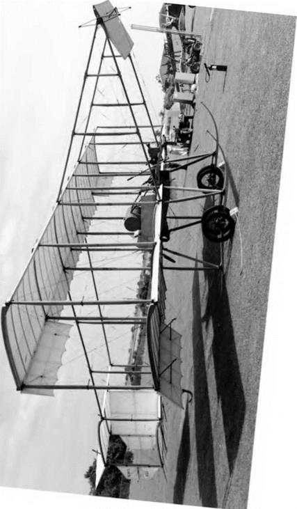
Fig 4F Pusher – old type (opposite)

The Bristol Boxkite. One blade of the small pusher propeller can be seen protruding behind and below the minimal wooden box fuselage with its barrel-shaped fuel tank.

Helix angle and blade angle

peller is laid flat on its boss on this horizontal plane, its axis being vertical (Fig. 4.10, overleaf). The figure shows how the blade angle is made up of the helix angle plus the angle of attack.

How it works

Each part of a propeller blade has a cross-section similar to that of an aero­foil; in fact, in some cases exactly the same shape of section has been used for both purposes. The thrust of the propeller is obtained because the chord at each part of the blade is inclined at a small angle (similar to the angle of attack of an aerofoil) to its direction of motion. Since, however, the propeller is both rotating and going forward, the direction of the airflow against the blade will be at some such angle as is shown in Figs 4.6 (overleaf) and 4.7 (later). This will result in lift and drag on the blade section, just as it does on an aerofoil. Actually in a propeller we are not so much concerned with the forces perpen­dicular and parallel to the airflow, i. e. lift and drag, as the force acting along the axis of the aeroplane (the thrust force) and at right angles to the rotation (the resistance force). So the total force on the blade must be resolved into thrust and resistance forces, as in Fig. 4.7. The difference between these and lift and drag is clearly seen by comparing Figs 4.6 and 4.7.

The total torque force on the propeller blades will cause a turning moment or torque which opposes the engine torque, and also tends to rotate the com­plete aeroplane in the opposite direction to that in which the propeller is revolving. When the propeller is revolving at a steady number of revolutions per minute, then the propeller torque and the engine torque will be exactly equal and opposite.

The propeller or airscrew

Of the various systems of propulsion, the propeller has been most used in the past, and for many types of aircraft it is likely to be a long time in dying. More and more gas turbines, rather than reciprocating engines, are being used for driving propellers but that does not in any way affect the aerodynamic prob­lems involved. It is right, therefore, that we should give brief consideration to those problems. Some of them also are common to those of the helicopter, some too to the blades of compressors and fans and turbines, and these are further reasons why we should consider them.

The object of the propeller is to convert the torque, or turning effect, given by the power of the engine, into a straightforward pull, or push, called thrust.

If an airscrew is in front of the engine it will cause tension in the shaft and so will pull the aeroplane – such an airscrew is called a tractor. If, on the other hand, it is behind the engine, it will push the aeroplane forward, and it is called a pusher (Figs 4F and 4G, later). In Fig. 4H (later) there is an unusual combi­nation of both pusher and tractor propellers.

High by-pass and turbofan engines

In order to make a jet engine more efficient, we need to arrange it so that a larger mass of air is somehow given a smaller increase in speed. The method used is to increase the size of the compressor fan and to allow a proportion of the air to pass round the outside of the engine. The momentum given to this ‘by-pass’ air contributes to the thrust. There are also a number of secondary advantages, the most significant being a reduction in noise. Another function of the by-pass air is to help cool the engine and to make use of some of the otherwise wasted heat to increase the thrust.

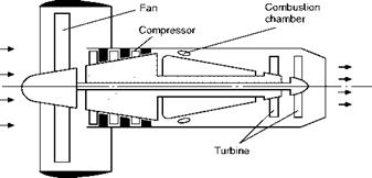
By increasing the amount of by-pass air, the so-called fan jet (see Fig. 4.5, overleaf) was evolved. The fan is not really part of the gas turbine compressor, and may sometimes be mounted at the rear of the engine.

Attempts to increase the efficiency still further lead to even larger fans until they become ducted propellers, or eventually unducted advanced turboprops, so that after many stages of development we will have come full circle back to the propeller! Lower by-pass engines will still however be required for very high-speed flight.

After so much talk of efficiency it is as well to remember that efficiency is not everything! We sometimes want value at all costs rather than value for money. The thrust given by a jet engine is almost independent of speed, while the thrust of a propeller, especially if it is of fixed pitch, falls off badly both above and below a certain speed. It is thrust that enables us to fly and gives us performance, and sometimes we may be more than willing to pay the price provided we get the thrust.

This seems an appropriate point at which to mention yet another difference between jet propulsion and propeller propulsion, one that is related to the fact just mentioned that the thrust of a jet is almost independent of speed; so the power developed by a jet engine, i. e. thrust X speed, varies with the speed and there is no satisfactory way of measuring it, either on the ground or in flight; when the aircraft is stationary on the ground, and the engine is running, there is no forward velocity – so the power is nil, but the thrust may be consider­able, and can be measured. That is why the performance capability of a jet engine – or of a rocket – is given in terms of thrust and not of power. But when an engine drives a propeller, and this applies whether the engine is of the turbine or piston type, the thrust, as we have said, is variable, but the power produced at the propeller shaft may be considerable even when the aircraft is stationary, and what is more it can be measured – the propeller acts as a brake on the engine, and the power is sometimes measured by other kinds of brake, and is sometimes called brake power – so these engines are compared according to the power they produce, and not by the thrust which would be meaningless.

High by-pass and turbofan engines

Fig 4.5 A turbofan engine

Engine and propeller propulsion

Finally, we come to the old and well-tried system of a propeller driven by an internal combustion engine (Figs 4.4 and 4E, overleaf). Here there is the clear dividing line between the propeller and the engine. We shall consider the pro­peller in more detail later in this chapter. There are, of course, some problems of airflow even in a reciprocating engine, and we may often use the ram effect of a forward-facing intake as an aid to raising the pressure of the incoming air, just as we may use the backward exhaust as a partial form of jet propulsion. In the cooling system we may even emulate the ramjet by col­lecting the air in ducts, using the otherwise wasted heat of the engine to give it energy, and ejecting it through a venturi tube – another little bit of jet propulsion. Or, of course, the engine that drives the propeller may itself be a gas turbine, and in this case we can allot almost at will the proportion of the power that we take from the propeller and from the jet respectively as in the turboprop system.

Thrust and momentum

All these systems have the common feature that they provide thrust as a result of giving momentum to the air, or other gases. In accordance with the princi­ples of mechanics the amount of thrust provided will be equal to the rate at which momentum is given to the air.

In symbols, if m kilograms is the mass of air affected per second, and if it is given an extra velocity of v metres per second by the propulsion device, then the momentum given to the air per second is mv, so

T = mv

Engine and propeller propulsion

Fig 4.4 Principle of propeller propulsion

Engine and propeller propulsion

Fig 4E Piston engine and propeller

The piston engine and propeller is still the most common arrangement for light general aviation aircraft.

Now clearly the same thrust could be provided by a large m and a small v, or by a small m and a large v; in other words, by giving a large mass of air a small extra velocity or a small mass of air a large extra velocity. Which will work best in practice?

Let us now work a step further in symbols and figures. To make life easy, we will choose to consider the case of a stationary aircraft, perhaps just about to start its take-off run. Now the rate at which kinetic energy is given to m kg of air per second to produce a slipstream or jet speed of vmk is 2 mv2 watts. So while 1 kg/s given 10 m/s has the same rate of momentum change and there­fore produces the same thrust as 10 kg/s given 1 m/s, the rate of change of energy of the former is

1 X 1 X 102 = 50 watts

2

and of the latter

— X 10 X l2 = 5 watts

2

It is clear therefore that the latter will require less work and that there will be less waste of energy; in other words, it will be more efficient than the former as a means of producing thrust.

From this point of view the propeller comes first because it throws back a large mass of air at comparatively low velocity, the jet engine comes next, and the rocket a bad third in that it throws back a very small mass at a very high velocity.

You may wonder therefore why propellers ever started to go out of fashion. The problem is that it is difficult to make them work well at high speed. Since the propeller has a rotational as well as a forward speed, it follows that the blade tips will start to move through the air faster than the speed of sound long before the rest of the aircraft. The occurrence of supersonic flow at the blade tips causes all sorts of problems, and although great advances in propeller design have been made, jet propulsion provides the only practical alternative for high-speed flight.