Category Modeling and Simulation of Aerospace Vehicle Dynamics

Aerodynamic expansions

The aerodynamic force is chosen as axial, side, and normal components in agreement with standard wind-tunnel con­ventions and the appropriate sign changes. There is no sign change in the moments. To prevent confusion with the normal force, the yawing moment is labeled LN.

efa)T~

‘-a’

(єта)Вр

~ L ~

=

Y

(єта)Вр

~

M

>/«)?

-N

(єта)1Р

LN L J

As practiced before, we expand the aerodynamic perturbations into Taylor series. From Fig. 7.1 we determine the linear derivatives for planar vehicles as

9A ЭА dA 9A 9A 9A

A — —и H——————— w H——- <7 H—— и H—— w H—— de

du dw dq du dw dSe

dY dY dY dY dY dY

Y = —— v + — p + — r 4—— v ——da ———– dr

dv dp dr di) dda ddr

Ar dN dN dN dN dN dN

N =——- и H—- w H—— о H—– й H—– w H—– de

du dw dq du dw dde

dL dL dL dL dL dL

L = —v ——— p 4— r + —v H——- da ——– dr

dv dp dr di) dda ddr

dM dM dM dM dM dM

Aerodynamic expansions

du dw dq4 du dw dde

Based on experimental evidence, the underlined terms are neglected, and the as­sumption is made that the acceleration terms, underlined twice, can be absorbed in the corresponding damping derivatives.

Wind-tunnel test data are usually presented as functions of Mach number M, angle of attack a, and sideslip angle /3, rather than the velocity components к, v, w. As before, we can expand the derivatives in terms of a and /3 and then replace a — w / Vr and ft = vjVr in order to reintroduce the state variables w and v (with small-angle assumption and Vr the reference speed).

Replacing the и dependence by the Mach number is more complicated and takes a few steps. Let us start with the definition of the nondimensional axial derivative

A = pV2SCA

The partial derivative relative to и has two terms, evaluated at reference conditions

dV

1 i2 эслэм

= PrVrSC A — r ou

r 2 dM ou r

Подпись: dA du Aerodynamic expansions

The first partial dV/du = 1 because V and и are changing by the same amount (small-angle assumption) and similarly dM/du = dV/{adи) = I /a (a is sonic speed). Therefore, with the dynamic pressure designated qr

suitable to receive experimental data

Aerodynamic expansions Подпись: (7.77)

^ = (prVrSCA, + – Cam ju + -——Ca^w + qrSCASeSe V &r / V r

N — { pTVTSCNr H—– С^м Jm + ^—-C^w + qrSC^Se8e

Aerodynamic expansions
ar / Vr

Подпись: Mw c n. 4rSc qrSc

Рг*г$сСтг – j – Сцім 1U CmaW

a, / Vr

Подпись: (7.78)

Aerodynamic expansions

H—2у (^ra« + qrScCm/je8e

+ qrSbC„Sa8a + qrSbC„Sr8r

All derivatives were nondimensionalized with the help of the reference area S, the chord c, and span b for longitudinal and lateral derivatives, respectively. The subscript r indicates the variables associated with the reference trajectory. They are in general a function of time. As an exception, however, the subscript r in the derivatives C/r and C„r refers to the perturbed yaw rate of the vehicle.

The coefficients of the reference trajectory CAr, C’Nr, and Cmr show up in the longitudinal aerodynamics of A, A, and M in conjunction with the forward velocity perturbation u. They are known functions of time. The terms in which they occur account for the fact that the dynamic pressure is increased (to the first order) by prVru, as we conclude from the following:

<Vr + uf * + 2Vru) = ^ + prVru

For steady reference flight the reference pitching moment Cmr is zero. However, for our pull-up and pushdown maneuvers, a reference pitching moment exists, and therefore the Cmr term should be included in the equations.

Herewith, we completed the modeling of the aerodynamics for the unsteady per­turbation equations. During the derivation, I made quite a few simplifying short­cuts. Only linear terms describe the model, and even some of these derivatives were assumed negligible based on some rather sketchy test results. Furthermore, the bending of the lifting surfaces, which could be quite substantial during high load factors, was not discussed, but could have been included in the derivatives Cjv„, Ст„, and C/,,. Yet we did accomplish our objective, i. e., to derive the un­steady perturbation equations in state-variable form for the vertical pull-up and push-down maneuvers for aircraft or cruise missiles. What remains is the summary of the results.
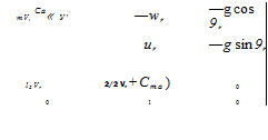
Подпись:Подпись:Подпись: PrVrS m irl, Подпись: Cf,Подпись: pr Vr Sc hПодпись: 8e State equations of vertical maneuvers.

The perturbation equa­tions of unsteady vertical maneuvers can finally be written in the desired matrix form by combining Eqs. (7.75) with (7.77) and (7.76) with (7.78). The six differ­ential equations are augmented by the integrals ф, в, and ф of the angular rates p, q, and r. As we inspect the nine differential equations, we discover that they can be decoupled into two sets of longitudinal and lateral equations. The longitudinal state vector is composed of u, w,q, and в, and the lateral state vector consists of the remaining v, р, г,ф, and ф variables.

with /[j = (/ц/33 – ф/Ізз, /33 = (hil33 – In)/hi – Now we have five linear differential equations in the lateral velocity component v, the roll and yaw rates p and r, and the derivative roll and yaw angles ф — p, ф = r. Notice how the reference pitch rate qr multiplied by a rather complicated ratio of the MOI components affects the rolling and yawing equations. Furthermore, the aileron and rudder controls couple into the yawing and rolling equations.

The matrix of Eq. (7.80) has the undesirable characteristic that its determinant is singular. You can verify that fact by multiplying the last two columns by g sin 9r and g cos 9r, respectively, and subtracting column 5 from column 4. The last column of the determinant is zero. A rank deficient matrix like this will cause you problems when you calculate its eigenvalues or try to control all of the state variables.

Fortunately, we can avoid that hazard by replacing the roll and yaw angles with the horizontal perturbation roll angle a. I will show you how to proceed. Because the angular perturbations are small angles, we can write them as an angular vector with the components ф, 9, and ф in the reference body coordinates. Transforming this angular vector into inertial coordinates (local level coordinates), using Eq. (7.74), we obtain the horizontal component a:

1

b Ф I

= [f]Brl

Ф

9

=

cos 9r 0 sin 9,- 0 1 0

Ф

9

r

Ф

—sin 9r 0 cos 9r

f

Подпись: a — ф cos 9r + ф sin 9rф cos вг + ф sin 9r = 9

—ф sin 9r + ф cos 9r

After taking the time derivative

a = ф cos 9r + ф sin 9r = p cos 9r + r sin 9r

Подпись: r a
Подпись: qlfChaSa QJr q-fCnJr lfCnSaSa
Подпись: V
Подпись: (7.81)

we replace the last two rows in Eq. (7.80), delete the last column, and replace the first element in the fourth column by g. The nonsingular lateral equations are now

qrS

mVr

wr

—ur

g

qrSb

vr b

qrSb2 p 21’nVrh

~ 1 QrSb2 f1 г’

qr + +cb>

0

qrSb s~<

Тъ~^Ггп$

(/ll — /2)+^ 1 qrSb2

Ф <1г+2фУ’П<’

2/’3Vr ^»r ^ ‘-‘"pS

0

0

COS er

sin er

0

Equations (7.79) and (7.81) are the preferred set of perturbation equations for vertical maneuvers, although we have to come to grips with the horizontal roll angle a.

The lateral and longitudinal equations are formulated in body-fixed coordinates. Their state vectors are the linear and angular velocity components parallel to the perturbed body axes. This form is most convenient for feedback control analysis because the state vector components and their time derivatives can be directly measured by onboard sensors. Note, however, that the state vector represents the perturbations from the reference trajectory. Therefore, only for the lateral equations can the state vector be measured directly. The measurements of the longitudinal variables contain both the reference and perturbation values. For flight-test data matching the reference values must be subtracted from the measurements to obtain the longitudinal perturbations.

Equations (7.79-7.81) can also serve as perturbation equations of steady flight. All you have to do is set qr = 0. Moreover, if the reference flight is horizontal, wr = 0, sin 0, = 0, cos 0r = 1, the equations are particularly simple. Finally, I hope that the derivation of the equations of motions for aircraft and cruise missiles during pull-up or push-down maneuvers gives you a good perception of the modeling of flight vehicle perturbations.

Perturbation Equations of Unsteady Flight

With a good understanding of perturbed steady flight, we can branch out and derive the perturbation equations for some important unsteady maneuvers. We focus on those flight conditions that maintain significant angular velocities, like the pull-up maneuver of an aircraft and the circular engagement of an air-to-air missile. In both cases we start with Eqs. (7.38) and (7.39), the general perturbation equations of unsteady flight and use the expansions of aerodynamic derivatives, Eq. (7.53) and (7.54). The resulting equations, expressed in state-variable format, are quite useful for specialized dynamic investigations of unsteady flight.

7.5.1 Aircraft Executing Vertical Maneuvers

Pull-ups of aircraft or push-down attacks of cruise missiles are maneuvers with sustained pitch angular velocities. They occur in the vertical plane and are sym­metrical maneuvers in the sense that the yawing and rolling rates are near zero. We proceed with expressing the perturbation equations in components, starting with Eq. (7.38).

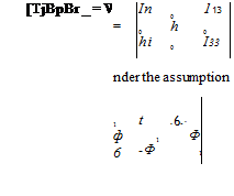
The state variables are the linear and angular velocity perturbations

Подпись:[evg]5p = [u v w], [єшВІ]Вр = [p q r], [eQ, BI]Bp —
Подпись: and ф, Perturbation Equations of Unsteady Flight

and for vehicles with planar symmetry, like aircraft or cruise missiles, the MOI tensor (same in reference and perturbed body coordinates) is

Now we specify the components of the reference maneuver. Because it is executed in the vertical plane, only the linear velocity components ur and wr and pitch rate q, are nonzero:

Подпись: 0 0 Яг 0 0 0 ~4r 0 0

Perturbation Equations of Unsteady Flight Подпись: (7.74)

[^r]5r = (Mr 0 uvl. o>’MBr = [0 q, 0], QBr/]Br

Substituting these components into Eq. (7.38), multiplying out the matrix products, and rearranging terms, yields the translational equations

й

—qrw — wrq

—COS0re

1

+ — m

efa)Bf

І)

—urr + wrp

+ £

sin0rl/f + cos вгф

w

qru + urq

—sin 6r0

The same substitutions into Eq. (7.39) lead to the rotational equations

InP + /13/

~hiP + (h – І33У

(ema)Bxp

hq

= qr

0

+

(sma)Bp

InP + /33/

(hi ~ h)p + Inr _

(ema)Bp

Подпись: =
Подпись: P 4 r Подпись: /зз(/зз - /2) +/?3 hi /33 — I n 0 /11 (/11 - /2) + If-3 _ p /11/33 - /х2з Подпись: + Perturbation Equations of Unsteady Flight Подпись: (7.76)

which, however, require further modifications. The left-hand side consists of more than one state vector derivative in the first and third components. The excess must be removed to arrive at a true state-variable representation. The terms I^r and /ізp can be eliminated by the following manipulations: 1) multiply the third row by /із and subtract it from the first row multiplied by /33, and 2) multiply the first row by /13 and subtract it from the third row multiplied by Iu. Neglecting terms that are multiplied by the small factors /із//33 and In/In furnishes finally the desired format:

Equations (7.75) and (7.76) are the perturbation equations for vertical maneuvers. On the left-hand sides remain only the time derivatives of the state variables. The effect caused by the unsteady reference flight is arranged in the first terms on the right-hand sides of the equations.

The gravity term of Eq. (7.75) is a function of the reference pitch angle, which can vary between 0 and 90 deg. Its perturbation variables are the Euler angles. The last terms of the dynamic equations contain the aerodynamic force and moment derivatives. We turn now to their assessment.

Flight-Path-Angle State Equations

For the design of a flight-path-angle tracker, we need the pitch dynamics ex­pressed in flight path angle у, pitch rate q, and its integral, pitch angle 9. Because this autopilot function is primarily for an aircraft, we take a slightly different ap­proach than in the preceding section. The lift force replaces the normal force. Therefore, the left-hand side of the third component of Eq. (7.55) mw is replaced by mVy, using the relationship [Eq. (7.62)]

mw — — та — —mV у

and the right-hand aerodynamics is formulated in terms of the lift force L. The symmetry conditions of the expansion Rule 1 apply as well for the lift as the normal force, but, alas, we have to put up with confusing notation. Aircraft aerodynamicists prefer lift to normal force and use L instead of Z or —A. They designate the rolling moment as LL, the convention we used earlier. From Fig. 7.1 we derive the linear derivatives and neglect the coupling and gravitational terms

mVу — Luu + Laot + Lqq + Ьйй + L^a + L$e8e (7.72)

Comparison with Eq. (7.59) shows that a tetragonal missile lacks the и derivatives. We neglect these m-dependent derivatives for the aircraft, and the damping effects La and L„ as well. By replacing a with a — 9-у, we succeed in deriving one of the state equations, after having absorbed m in the denominator of the derivatives:

Подпись: La n у = —9 У VLa, L&e

— у Л—— oe

V У V

The other state equations follow directly form Eq. (7.58):

q — Mqq + Ma9 — May + M$e 8e

Both equations combined yield the desired flight-path-angle formulation

Подпись: 4 ~Mq Ma -Ma " q M^e 9 = 1 0 0 9 + 0 Y 0 La/V -La/V Y Lbe/V Подпись: 8e(7.73)

Подпись: r Flight-Path-Angle State Equations Подпись: qS La = —CLa m Подпись: -‘be Flight-Path-Angle State Equations Подпись: qSc h Подпись: г n
Подпись: qSc2 2hV
Подпись: Ma

where the dimensional derivatives are calculated from the nondimensional deriva­tives according to

These equations, in state variable format, are used in Sec. 10.2.2.6 to develop a self-adaptive flight-path-angle tracker. I am always amazed how plant equations, as simple as Eq. (7.73), produce useful models for autopilot designs, which can be implemented in six-DoF simulations.

These examples should be enough to help you develop other linear models for aerospace vehicles. We covered the roll transfer function, pitch dynamics expressed in normal acceleration, and flight-path-angle dynamics. You should be able to derive the yawing equations, the roll/yaw coupled dynamics, and the full linear stability equations of steady flight. We turn now to applications of unsteady flight.

Pitch Dynamic Equations

The uncoupled pitch dynamics consist of the pitching moment equation, second of Eq. (7.56), and the normal force equation, third of Eq. (7.55). This example is for tetragonal missiles. We therefore use Fig. 7.2 to write down the nonvanishing linear derivatives

I2q = Mww + Mqq + + MSq8q

Instead of w we prefer the expansion in terms of the angle of attack a and merge M& into Mq (quite common for missiles). Furthermore, to conform to conventions the derivatives are divided by the pitch moment of inertia /2 but retain their letter symbol M:

q — Маа + Mqq + Msq8q (7.58)

We model the normal force dynamics by the third component of Eq. (7.55). Neglecting the gravitational term and the centrifugal term mqur, we have (but see Problem 7.6)

mu> = Zww + Zqq + Z^w + Zsq8q (7.59)

Again, we replace w by a, neglect all damping derivatives, and furthermore follow missile conventions, replacing Z by —N (normal force) and the vertical accelera­tion u> by the normal acceleration —a. Redefining the normal force derivatives N by including the mass in the denominator, we formulate

a = Naa + N$q8q (7.60)

Equations (7.58) and (7.60) will be used for an acceleration autopilot design with inner rate-loop damping. Commonly, only pitch gyros and accelerometers are available as sensors, but not angle of attack. The a dependency must therefore be eliminated. You accomplish this feat by first taking the derivative of Eq. (7.60):

a = Nade + Nsq8q (7.61)

Then recalling that the normal acceleration a is proportional to the flight-path-angle rate у (f°r small a).

a = Vy (7.62)

and with the kinematic relationship у = q — a

a=Vy = V(q— a) (7.63)

Solving for a and substituting into Eq. (7.61)

Na

a = Naq – —a + NSq8q (7.64)

Now, premultiply Eq. (7.58) by Na and (7.60) by Ma, subtract them from each other, and then solve for q. You derived the important result without a dependency:

і, Ma (MaNgq^ /-7 сеч

q = Mqq + — a + I MSq———– 1 JSq (7.65)

Equations (7.64) and (7.65) are the state equations for a and q. The derivative of the pitch control Sq of Eq. (7.64) is acquired from a first-order actuator, as shown in Fig. 7.3. It provides the third state equation

Sq = Xu — kSq (7.66)

Pitch Dynamic Equations Подпись: (7.67)

with и the commanded input and 1 /X the actuator time constant. Substituting this Sq into Eq. (7.64) yields

Pitch Dynamic Equations Подпись: Mi Подпись: (7.68)

Collecting the three equations (7.65-7.67) yields the desired result:

Подпись: и Pitch Dynamic Equations Подпись: 8q

These state equations in pitch rate q, normal acceleration a, and pitch control Sq are quite useful for autopilot design. Particularly, we succeeded in replacing a by a, therefore replacing the difficult to implement angle-of-attack sensor by the readily available accelerometer from the INS.

Fig. 7.3 Actuator dynamics.

Pitch Dynamic Equations Pitch Dynamic Equations

The dimensional derivatives Na, NSq, Ma, Mq, Mgq are related to the nondi- mensional derivatives CNa, CNSq, Cm„, Cm?, Cmsq by

where d is the missile diameter and S the maximum cross section.

Sometimes autopilots are designed without consideration of actuator dynamics. For these simplified circumstances we set Sq = 0; thus, fromEq. (7.66) Xu = XSq. Neglecting N$q Ma/Na against the significantly larger Мц, we gained the reduced – order state equations

(7.69)

These pitch-plane equations, which depend on pitch rate q and normal acceleration a as state variables only and have the pitch control 8q as input, play an important role in the design of air-to-air missile autopilots. Because of their simplicity as plant descriptor, a self-adaptive autopilot can be constructed around them. I present the details in Sec. 10.2.2.4.

The discussion would be incomplete, however, without also reintroducing the angle of attack as one of the state variables. Substituting Eq. (7.63) into Eq. (7.61) eliminates the acceleration a completely, and we are left with

Подпись:Pitch Dynamic Equations8q

Подпись: 4 a Подпись: (7.70)

which we use to replace the a equation in Eq. (7.69):

We will make use of this format when we design the rate autopilot in Sec. 10.2.2.1. There, we will derive the q(s)/8q(s) transfer function by eliminating a, thus by­passing the need for an a sensor.

Similarly, the lateral acceleration equations with the state variables’ yaw rate r and sideslip angle f}, and the control input 8r are (see Problem 7.1)

(7.71)

where LN designates the yawing moment derivative (to avoid confusion with the normal force derivative N).

Roll Transfer Function

The simplest application is probably the roll channel, uncoupled from the other degrees of freedom. From Eq. (7.56) we select the first component equation and scan Fig. 7.1 for the existing roll derivatives

Because we neglect cross-coupling, there remains just

InP — Lpp + LspSp

and the transfer function is

P(s) _ L5p/Iu
Sp(s) s – Lp/1\

The mass properties are commonly lumped into the derivative, and the nomencla­ture LL is used for L to avoid confusion with the designation for lift. Furthermore, because we emphasize here the aircraft, we replace Sp by the aileron symbol 8a:

Подпись:P(s) _ LLSa
8a(s) s — LLp

I shall use this transfer function for the roll autopilot design in Sec. 10.2.2.2. LLga and LLp are the dimensioned roll control and damping derivatives, evaluated at the reference flight. They are related to the nondimensional derivatives C/Ja and Cip by LLSa = {qSb/lu)Cha and LLP = {qSb/In)(b/2V)Cip, where q is the dynamic pressure, S the reference area, b the wing span, and V the vehicle speed.

Perturbation Equations of Steady Flight

Подпись: + Perturbation Equations of Steady Flight Подпись: (7.53)

After this excursion into aerodynamic modeling, let us pick up the discussion from Sec. 7.2. The equations of motion, Eqs. (7.28) and (7.29), must be completed by the aerodynamic expansions of the right-hand sides. The linear terms of the Taylor expansion can be grouped according to the state variables

Perturbation Equations of Steady Flight

and

[i. e., frame A = frame 1 results in [evBBp — ev’BBp according to Eq. (7.8), and

Подпись:

Perturbation Equations of Steady Flight

devB d t

Подпись: (7.55)+ tef,]Bp + ([T]BpBr – [E])[T]Br,[fgr]1

Perturbation Equations of Steady Flight Perturbation Equations of Steady Flight

and Euler’s equation

These fundamental stability equations of steady flight are fully coupled by the state variables [svlB]Bp and appearing in the aerodynamic terms and

in addition by [coBpBr]Bp being present on the left-hand side of Eq. (7.55). They are now linear differential equations, possibly with time-dependent coefficients through the variable Mach number. The controls [erfBp are the inhomogeneous input to the equations.

The acceleration variable [ev’BBp appears on both sides of Eq. (7.55). For a state-space representation they would have to be combined. Yet frequently in the aerodynamic expansions, [evB]Bp is expressed as d. fi and, particularly in missile dynamics, often combined with the damping effect caused by [coBpBr]Bp, thus eliminating the acceleration term on the right-hand sides.

For even greater simplicity the coupling term m[QBpBrBpvl/jr}Br is usually neglected in the development of plant dynamics for autopilot designs, and so are the thrust perturbations and the gravitational term. We will follow this practice as we derive transfer and state equations for roll, acceleration, rate, and flight-path angle autopilots.

Derivative maps

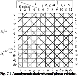
As you build your aerodynamic model, you have to apply the vanishing-derivative rules numerous times. Just for the linear deriva­tives it would be 72 times. To save you time, I supply maps that let you determine the existence of derivatives by inspection of their grid pattern. They apply for up to third-order derivatives for aircraft and up to second-order derivatives for missiles.

Figure 7.1 graphically patterns Eq. (7.51) and the associated Rule 1 for planar vehicle derivatives up to third order. In the following discussion, however, rather than referring to the vanishing derivatives, I will emphasize those that survive the sifting process.

Depending on the force components і, the order of the derivative, and the even or odd integer of the third superscript, the existence of the derivative is indicated by two symbols—cruciform or box—in the top table of Fig. 7.1. For instance, for the first-order derivative Xu the table assigns a cruciform symbol to the force compo­nent X. To determine existence, refer to the single row array. Because Xu is asso­ciated with a cruciform symbol, it exists. However, Xv, having a box symbol in the array, vanishes because it does not show the required cruciform symbol of the table. Moving into the next column of the table, the first order derivative Lgp must have a box symbol. The single array confirms its existence. You can use this array to deter­mine quickly, which derivatives you must include in you linear aerodynamic model.

For second-order derivatives D’n the symbols are reversed in the table of Fig. 7.1, and the 12 x 12 array is used to determine their existence. The array is symmetric because the order of taking partial derivatives is irrelevant (assum­ing continuous functions). Therefore, you can start with either rows or columns. For example, Zwsq, requiring the box symbol, exists according to the array, but Ywgq, associated with the cruciform pattern, vanishes. About 198 second-order derivatives exist. It is up to the aerodynamicist to determine their significance and magnitude. Hopefully, if called to model nonlinear effects, you can neglect most of them, but only after you have reasoned through all exclusions.

Third-order derivatives must be separated into two groups, depending on an even or odd third-order superscript (even or odd refers to the position number of the variable in the state vector). If the last superscript is even, e. g., v, the cruciform

Derivative maps

symbol is associated with a derivative such as Zwrv. Entering the square array with w and r indicates existence of that derivative. Let us check out our first example LUqSq — D511 of Eq. (7.47) for planar vehicles. Its third superscript is odd, and because L is in the second column, the cruciform symbol applies. The square array entry with и and q requires the box symbol; therefore, the derivative vanishes.

For vehicles with tetragonal symmetry, a compact graphic display is possible only for first – and second-order derivatives. Figure 7.2 summarizes both Eqs. (7.51) and (7.52) or Rules 1 and 2. The table in Fig. 7.2 assigns different symbols for the existence of four groups of derivatives. For instance, Xu exists, and Xv vanishes; Zuw survives, but Zusp does not. I am sure by now you have caught on to my scheme.

The graphical aids of both figures can be used to determine uniquely the existence or nonexistence of aerodynamic derivatives. A significant number of derivatives can be eliminated by symmetry alone. Reflectional symmetry eliminates about half of the linear candidates, and because the square array is symmetrical, only approximately a quarter of the second – and third-order derivatives need be consid­ered. For vehicles with tetragonal symmetry, these numbers are further reduced by a factor of one-half.

I already mentioned earlier that some of the state variables could also be replaced by other relevant quantities. Particularly, the substitutions of a for w and ft for v are

quite common. Also и is often replaced by the Mach-number dependence. Similar alternatives are used for w —> a and v —> $. The controls Sp. Sq, Sr refer either to the missile’s roll, pitch, and yaw or the aircraft’s aileron, elevator, and rudder.

The coordinate system of the expansion variables is the dynamic system. In most cases the body coordinates serve as the dynamic system. For an aircraft in steady flight, the reference body axes are the inertial axes, and during its perturbed flight the body axes become the coordinate system for the aerodynamic expansion. Fre­quently, the stability axes (special body axes) are used. However, other possibilities must also be considered. For a spinning missile the dynamic coordinates are as­sociated with the nonspinning body frame. Because this glove-like frame also has rotational symmetry, the derivatives are expressed in these coordinates, and Rule 2 applies. A similar situation exists for Magnus rotors (see Sec. 10.1.1.4) or spinning golf balls. Their spin axes, however, are essentially normal to the velocity vector. Thus the nonspinning frame exhibits planar symmetry, and Rule 1 should be used.

The modeling of the aerodynamics for computer simulations frequently includes tabular look-up for variables with large variations, and the Taylor expansion is only carried out for those variables that remain small. So far, we have dealt with complete expansions of all 12 components of the state vector. With minor modifications the results are applicable also to these incomplete expansions.

For instance, if the aerodynamics is expressed as tabular functions of the ve­locity component u, the Taylor series is carried out in terms of the state variable components 2 through 12 only. All derivatives remain implicit functions of u, and
the order of the derivatives is reduced by one. For example, an aircraft’s Xwsq(u) derivative is modeled by a one-dimensional table. Instead of a table, it also could be completely expanded in powers of u, provided the polynomial fits the data:

Xwbq^M) — Xuw$qU -|- Xu2wfiqU -|- Xulw$qU -|-

Please confirm the existence of the derivatives on the left – and the right-hand sides.

This procedure applies to any derivative and any state variable component. Also more than one variable can be replaced by implicit functions. We will use this approach in several instances. In Sec. 10.2.1 you will see it applied to aircraft and missile six-DoF models. For the CADAC FALCON6 simulation I will introduce reduced derivatives that are implicit functions of Mach, angle of attack, and, in some cases, also of sideslip angle. The CADAC SRAAM6 air-to-air missile model, using aeroballistic instead of body axes, can also be pressed into this scheme, and you will see that most derivatives are implicit functions of Mach and total angle of attack. Finally, the CADAC GHAME6 hypersonic vehicle is a straight expansion of derivatives with Mach and angle of attack as implicit variables.

The most frequently encountered task, however, is the linear expansion of the aerodynamic derivatives. I will demonstrate the procedure for the linear perturba­tion equations of steady flight and specifically derive some simple state equations that are needed for our autopilot designs in Sec. 10.2.2. A further sophistication is the extension to unsteady flight like missiles in pushover and terminal dive or in lateral turns.

Configurational symmetries

Most aircraft and guided missiles have a planar or cruciform external shape. The planar configuration dominates among aircraft and cruise missiles, while missiles that execute rapid terminal maneuvers have cruciform airframes. Two types of symmetry are, therefore, con­sidered: reflectional and tetragonal (90 deg rotational) symmetries.

To derive the conditions of vanishing derivatives, precise definitions of these symmetries are required. In the case of reflectional symmetry, the existence of a
plane, satisfying certain conditions, is required, whereas tetragonal symmetry calls for an axis with specific characteristics.

In Chapter 2,1 introduced the reflection tensors M and in Chapter 4 the tetragonal symmetry tensor R<x). In body coordinates they have the form

[Mf =

"l

0

1

H – о

О О

___ _l

and |^9о Iй =

"l 0 0 0

о”

-1

0

0 1

0 1

0

[/?9o]B, with a determinant of +1, is a proper rotation, whereas [MH is improper because its determinant value is — 1. For an aircraft the displacement vectors ssp, originating from the symmetry plane and extending to the surface, occur in pairs, related by

s’SP = MsSP

and similarly, for a missile, the displacement vectors ssa, reaching from the sym­metry axis to the surface, also occur in pairs related by

s’sa — ^90 ssa

These relationships together with the PMI, already encountered in earlier chapters, lead us to the desired conditions for vanishing derivatives. Noll3 has provided a precise mathematical formulation. Applied to the aerodynamic problem at hand, the PMI asserts that the physical process of generating aerodynamic forces <7,- from the variables zj is independent of spatial attitude. For any rotation tensor Rin, in tensor subscript notation and summation over repeated indices, it states

Rmdn{zj} = di{Rjpzp} (7.48)

Read Eq. (7.48) with me from left to right: the vector valued function dn of the state vector zj, rotated through the rigid rotation Rm, equals the same vector valued function of the state variables rotated through the same tensor Rjp. A functional with the properties expressed by Eq. (7.48) is called an isotropic function. The rotation is allowed to be proper or improper; i. e., its determinant can be plus or minus one.

Let us apply the PMI first to planar vehicles. Suppose Eq. (7.45) describes the aerodynamics of a particular wind-tunnel test result:

У І = di{zj)

Consider a second test under the same conditions, but with flow variables Zj mirrored by the reflection tensor Mjm

У і — di{MjPZp]

The resulting aerodynamics y’ should also be mirrored.

y = Mmyn

Therefore, equating the last two relationships, and with Eq. (7.45), we obtain

Mmd„{zj} = dilMjpZp] (7.49)

just like the PMI, Eq. (7.48) states. But if the external configuration of the test object possesses planar symmetry, the aerodynamics is indistinguishable in the two tests

di{zj} = dt {MjpZp}

and therefore substituting into Eq. (7.49) we obtain the condition for vanishing derivatives

Mindn{Zj} = di{Zj} (7.50)

We expanded both sides in Taylor series. In body coordinates the elements of Mm consist of +1 and -1 terms only. Those derivatives that exhibit different signs because of Min must be zero! If you read my paper, you will see that the derivation is somewhat more complicated. Yet Eq. (7.50), with the abbreviation of Eq. (7.46), leads eventually to the relationship between the derivatives:

j-yhh’-ji. _ j-_____ |^2д+&+і’ + 1 jyhh’"Jk

Rule 1: The aerodynamic derivatives Щ’,г "1к of a vehicle with reflectional

symmetry vanish if the sum Е Д. + к + і + 1 is an odd number.

When the exponent of ( — 1) is odd, a negative sign will appear at the right-hand side of Eq. (7.51). The same derivatives with different signs can only be equal if their values are zero. The subscript і indicates the force or moment components and the superscripts j, j2, ■ ■ ■, jk designate the components of the state vector of the of the kth partial derivative. To convert from the derivatives with physical variables to their subscript notation Т)/‘л"’л, use Table 7.1.

Let us apply Rule 1 to the example, Eq. (7.47): ‘Ejk+k + i + 1 =(1+5 + 11) + 3+4+1 =25. The derivative does not exist; a result you would have predicted if you are an aerodynamicist.

To derive the condition for vanishing aerodynamic derivatives of vehicles with tetragonal symmetry, we make use of the fact that a cruciform vehicle has two

Table 7.1 Association of dependent and independent variables with subscripts and superscripts

ij

j

і

1

u

X

2

V

Y

3

w

Z

4

p

L

5

q

M

6

r

N

7

u

8

V

9

w

10

Sp

11

Sq

12

Sr

planes of reflectional symmetry. The two planes are rotated into each other by the tetragonal symmetry tensor Д90, and they intersect at the axis of symmetry. The PMI is applied twice to the two symmetry planes. The first one we carried out already for the reflectional symmetry plane. Therefore, Rule 1 applies also to cruciform vehicles. We derive the second condition by rotating the original experiment through 90 deg and applying the PMI the second time. I will spare you the details. The result is the relationship

Подпись: (7.52)(jqq2–qk _ +£+/>+1 Qqxqv-qk

where C is related to the D derivative by simply exchanging every second or third subscript. Thus the rule for vanishing derivatives for cruciform vehicles is stated as follows.

Rule 2: The aerodynamic derivative D’n"Jk of a vehicle with tetragonal

symmetry vanishes if the sum Ед + к + і + 1 is an odd number (Rule 1) or if Yqk + к + p + 1 is an odd number as well.

The relationship of the subscripts between oJiur"Jk and cqpqi"4k is given by Table 7.2.

As a test case, do you expect Nwp$q to exist for an aircraft or a missile? It is the control-coupling derivative of pitch control Sq, contributing to the yawing moment N, in the presence of a vertical velocity component w and roll rate p. For an aircraft we have Nwpgq = T>|411. Applying Rule 1, Ед + к + і + 1 = 3 + 4+11+3 + 6+1 = 28, we get an even number, and therefore the derivative is nonzero. For a missile, with Rule 2, Cf412 = 411, and Eqk + к + p + 1 =

2 + 4+12 + 3+ 5 + 1 =27 is an odd number, and the derivative vanishes. Did you guess correctly?

Let us try another example: Ywsr = D 12 is the yawing force derivative Y caused by rudder control Sr in the presence of down wash w. It survives the test for planar

Table 7.2 Subscript and superscript relationship between the D and C derivatives

i, jk

P’Qk

1

1

2

3

3

2

4

4

5

6

6

5

7

7

8

9

9

8

10

10

11

•12

12

11

vehicles (from Rule l:Ejj + f+i + l = 3 + 12 + 2 + 2+1 = 20), indicating that, for aircraft, the derivative is linearly dependent on the downwash. For missiles, however, with Cf11 = D12 (Rule 2: ‘Eqi +k + p +1 =2+11+2 + 3 + 1 = 19), the derivative does not exist. Physically speaking, the downwash is symmetrical for cruciform configurations. It affects the side force not linearly, which would result in a sign change, but quadratically, as shown by the existence of the derivative Yw28r — з — c|2 1 ^ : Syt + & + г + I = 3 + 3+12 + 3 + 2 + 1 = 24, and Zq^ + k + p+ l= 2 + 2+ ll + 3+ 3 + l= 22.

These rules are quite helpful not only for modeling but also for investigating nonlinear effects. I put them to good use in my dissertation, describing the nonlinear aerodynamic phenomena of Magnus rotors with higher-order derivatives. The real challenge of course is the extraction of these derivatives from wind-tunnel or free – flight tests, which we leave to the expert.

I do not have space here to discuss the physical interpretation of aerodynamic derivatives in any more detail. You will find the linear derivatives explained by Pamadi6 or Etkin.1 For nonlinear phenomena you have to search the specialist literature that applies to your particular modeling problem.

Aerodynamic Symmetry of Aircraft and Missiles

The number of aerodynamic derivatives in the Taylor series increases vastly with higher-order terms. Even the linear derivatives add up to 12 x 6 = 72, more than the aerodynamicist would like to deal with. Fortunately, the configurational symmetries of aircraft and missiles reduce the number of nonzero derivatives drastically.

Maple and Synge4 investigated the vanishing of aerodynamic derivatives in the presence of rotational and reflectional symmetries. They considered the dependence of the aerodynamic forces on linear and angular velocities only and employed complex variables to derive the results. The Maple-Synge theory con­tributed to the solution of many nonlinear ballistic problems in the past. However, with the advent of guided missiles the dependency of the aerodynamic forces on unsteady flow effects and control effectiveness has gained in importance.

In my dissertation and later in a paper5 I derived, starting with the Principle of Material Indifference, rules of vanishing derivatives for aircraft and guided missiles. The aerodynamic forces are assumed functions of linear and angular velocities, linear accelerations, and control surface deflections. I will summarize the results with enough detail so that you can apply the rules successfully, but spare you the derivations. For the curious among you, my paper provides the details.

The functional form of Eqs. (7.40) and (7.41) will be used, but subscript notations will be substituted for the dependent and independent variables. The kth-order derivative of the Taylor-series expansion will be formulated in these subscripts. After reviewing the planar and tetragonal symmetry tensors, thought experiments are conducted that engage the Principle of Material Difference in discarding zero derivatives. Rules will be given for vanishing derivatives by adding up sub – and superscripts. For ease of application, two charts are presented that sift out the vanishing derivatives up to second order for missiles and up to third order for aircraft.

7.3.1.1 Taylor-series expansion. We begin with the aerodynamic func­tionals of Eqs. (7.40) and (7.41), select the dynamic coordinate system, and introduce components for the forces, moments, and dependent variables:

(7.42)

The acceleration components require additional comments. The [DAvB]D_deriva­tive must be transferred to the D frame before it can be expressed as [vABD = [й, i), tii] components

[Davab]° = [Ddva]D + [£2“]dK]D = [vAB]° +

The additional term [£2ZM]D[t;g]£> is absorbed in the [t^J and (coBA ] dependencies. Now we introduce the subscripted independent variables

Zj = {u, v, to, p, q, г, й, v, tii, 8p, 8q, 8r}, 7 = 1,2,…, 12 (7.43)

The two velocity components v and to, if expressed in body coordinates, can also be viewed as angle of attack а = arctan(io/и) and side-slip angle fi = arcsin(v/y/u2 + v2 4- to2). The variables 8p,8q,8r represent the missile
controls—roll, pitch, and yaw—or the aircraft effectors—aileron, elevator and rudder. The dependent variables are abbreviated by

yi = {X, Y,Z, L,M, N}; i = 1,2,…, 6 (7.44)

With these abbreviations Eq. (7.42) can be summarized as

УІ = di(Zj); і = 1,2,…. 6; j = 1, 2,…, 12 (7.45)

Aerodynamic Symmetry of Aircraft and Missiles Aerodynamic Symmetry of Aircraft and Missiles

The aerodynamic functional is expanded into a Taylor series in terms of the 12 state variable components zj, relative to the reference state zj. The Taylor expansion is mathematically justified if the partial derivatives in the expansion are continuous and the expansion variables A Zj = Zj – Zj are small. For aircraft and missiles the aerodynamic forces are continuous functions of their states for most flight maneuvers. However, unsteady effects, such as vortex shedding, can introduce discontinuities that cannot be presented accurately by this method. In subscript notation the Taylor series assumes the form

Подпись: J2"'jk Подпись: 1 / dkdj k'- эг/, ■■■dzjt Подпись: (7.46)

The partial derivatives, evaluated at the reference flight conditions, are the aerody­namic derivatives. The kih derivative is а к + 1 order tensor and is abbreviated by

It is a function of the implicit variables M and Re. As an example, the third-order rolling moment derivative with і = 4, j = 1, 72 = 5, 73 = 11 becomes, by correlating the subscripts with Eqs. (7.43) and (7.44),

84 ■ ■ ■ = ~-Э-_Е_ = L (7.47)

dz.1dz.5dzn dudqd(8q) Uqbq

This is the rolling moment derivative caused by the forward velocity component u, the pitch rate q, and the pitch control deflection Sq.

Aerodynamic Forces and Moments

The most difficult problem in atmospheric flight mechanics is the mathematical modeling of the aerodynamic forces in a form that can be analyzed and evaluated quantitatively. Because the functional form is not known, the aerodynamic force functions are expanded in Taylor series in terms of the state variables relative to a reference flight. Even for digital computer simulations, restrictions for storage and computer time require that the number of independent variables in the aero­dynamic tables be kept to a minimum. The dependency on the other variables then is expressed analytically by Taylor-series expansions.

For analytical studies a complete expansion is carried out for all state variables. There are two requirements that must be met. First, the partial derivatives of the expansions must be continuous—a condition that is usually satisfied; and second, the expansion variables must be small. In generating the aerodynamic forces three frames are involved: the atmosphere-fixed frame A, the body frame B, and the relative wind frame W. If the air is in uniform rectilinear motion relative to an inertial frame, A itself is an inertial frame. The wind frame has the c. m. of the vehicle as one of its points.

Usually it is postulated that the aerodynamic forces depend on external shape and size (represented by length /), atmospheric density p, and pressure p, the linear velocity of the airframe, c. m. relative to the atmosphere v д, the angular velocity of the body relative to atmosphere шВА, the acceleration of the c. m. wrt the atmosphere DAv g and, finally, the control surface deflections rj. In summary, the functional form is

fa = //(Л P, P, «BA, DAvj, V) (7.40)

The same functional relationship holds for the aerodynamic moment.

ma = /т(/, p, p, vAB, uBA, DAvA, rj) (7.41)

The expansions, called force expansion according to Hopkin,2 are carried out in the form of Eqs. (7.40) and (7.41). Variables that remain small throughout the perturbed flight must be identified. If the body frame does not yield these variables, the dynamic frame of the preceding section is introduced. As an example, a spinning missile requires a nonrotating body frame as dynamic frame.