Category Principles of Helicopter Aerodynamics Second Edition

Smoke Flow Visualization

Smoke flow visualization studies of subscale helicopter rotor wakes has been performed by Gray (1956), Pizialli & Trenka (1970), Landgrebe (1971,1972), Brand et al. (1990), Mercker & Pengel (1992), Ghee & Elliott (1995), Martin et al. (1999), and many other investigators. A dense white smoke is entrained into the rotor wake and blade tip vortices. When stroboscopically illuminated, the smoke particles reflect light, allowing a photograph of the flow structure to be recorded.[39] The tip vortices appear as circular regions devoid of smoke, which is a result of centrifugal forces produced on the smoke particles near the vortex cores (see later). Ideally, to give accurate spatial information, the wake must be illuminated using a thin light sheet, preferably using a laser. In another form of smoke flow visualization, smoke is ejected from the blade tip directly into the tip vortices. This renders the vortices visible as 3-D tubular trails with central voids. Such methods have been used to visualize the tip vortices in hover [see Gray (1956)] and in forward flight [see Muller (1990a)]. In a water tunnel, dye ejected from the blade tips gives similar results – see Werle & Armand (1969). Projected smoke filament techniques, such as those developed by Steinhoff (1985) and Muller (1990b, 1994), have also received some attention.

While the application of smoke visualization techniques has had good success for sub­scale rotor models, experiments on full-scale helicopter rotors are rare. A general limitation

of the smoke flow technique, however, is that smoke particles are quickly dispersed, and lower particle concentrations make the tip vortices harder to visualize. However, by using smoke “bombs” attached to the blade tips, the method has been used to visualize part of the wake structure of a CH-46 tandem rotor helicopter – see Spencer (1969) and Stemfeld & Schairer (1969). Using the same technique, the wake generated by a coaxial Ka-34 helicopter has been documented by Akimov et al. (1994).

Natural Condensation Effects

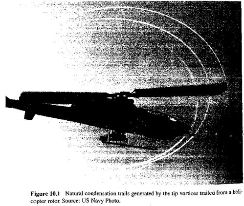
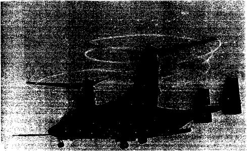
Evidence of the rotor wake can sometimes be seen through natural condensation of water vapor inside the blade tip vortices. Published photographs of the phenomena are relatively rare, but examples are given by Felker et al. (1986), Campbell & Chambers (1994), and McVeigh et al. (1997). Representative examples are shown in Fig. 10. і and Fig. 10.2, with another being shown previously in Fig. 2.2. The results obtained often appear similar to smoke flow visualization, exhibiting characteristic tubular trails with large central voids marking the positions of the vortices. These voids are caused by centripetal accelerations

Natural Condensation Effects

Natural Condensation Effects

Figure 10.2 Natural condensation trails in the tip vortices generated by a tilt-rotor aircraft. Source: Courtesy of US Navy, Patuxent Naval Air Station.

on the vapor particles as well as by the thermodynamic aspects of the problem. Although condensation flow visualization has been achieved in a wind tunnel environment [Dadone

(1970) ] it is usually only outdoors that the correct combination of atmospheric conditions exist, that is, when the air temperature and dew point spread are small. Even then, however, a challenge is to have the right lighting conditions and background contrast to allow a good photographic exposure.

Flow Visualization Techniques

While the wake of a helicopter rotor is sometimes rendered visible through natural condensation effects, flow visualization using subscale rotor models has been the primary method used to study the wake physics. Some of the earliest studies were by Taylor (1950) and Dingeldein (1954), who used balsa dust to visualize the rotor wake. A more popular method is to use a dense white smoke, which is entrained into the wake, thereby rendering it visible when illuminated by a suitable strobed lighting source. Density gradient flow visualization methods, such as strobed (phase-resolved) shadowgraphy and schlieren (and to a lesser extent, interferometry), have also been used to study helicopter rotor wakes The phenomena that have been studied include tip vortex formation, blade-vortex interac­tions, vortex-airframe surface interactions, main rotor wake-tail rotor interactions, ground interference, multirotor flows, and the wake roll-up in forward flight.

Rotor Wakes and Blade Tip Vortices

We have built new rotor test stands, new blades, with emphasis on heavily instrumented blades, new measurement techniques – it is mind boggling to me to see how well, and in how much detail, we can measure the flow field of a rotor. Modeling the flow field of a rotor is a terribly difficult problem. The airplane people have it easy compared to us. Capturing the details of the rotor wake and of what happens in the vicinity of the blade is very difficult.

Leone U. Dadone (1995)

10.1 Introduction

The significant physical features of helicopter rotor wakes, and some of the more advanced mathematical tools for modeling the wake, are discussed in this chapter. The understanding and prediction of the effects of the rotor wake is an important key to the successful prediction of blade loads and a host of other problems found in helicopter aero­dynamics. A helicopter rotor wake is dominated by strong vortices that are trailed from the tips of each blade. The nature of the rotor wake, in terms of its geometry, strength, and the aerodynamic effects produced on the blades, depends principally on the operating state and flight condition of the helicopter. In hover, the tip vortices follow nominally heli­cal trajectories below the rotor. This is perhaps the simplest operating state to understand, but even here the wake structure is relatively complicated. During forward flight, the rotor wake is skewed back behind the rotor by the oncoming flow, and a series of more complex interlocking, but nominally epicycloidal vortex trajectories are produced. Under these con­ditions, the increased mutual proximity of many of the vortex filaments results in stronger vortex-vortex interactions and complicated distortions to the evolving wake topology. At the lateral edges of the wake, the individual vortex filaments are found to roll up into a pair of merging vortex bundles, somewhat like those that would trail from the tips of a low aspect ratio fixed-wing.

The highly 3-D nature of a helicopter rotor wake, as well as the sensitivity of the wake to the geometric and operational parameters of the helicopter, means that the details of the wake flow are difficult to study experimentally, as well as to compute by means of mathematical models. Recent advances in experimental techniques have been substantial and now allow measurements to be made with a fidelity that was impossible only a few years ago. However, there are many physical phenomena involving the formation and evo­lution of blade tip vortices and rotor wakes that are still not well understood, and it is here that future research on helicopter aerodynamics must be focused. Landgrebe (1988) and McCroskey (1995) review the state-of-the-art capabilities in modeling helicopter rotor wakes, whereas Leishman & Bagai (1998) give an overview of key characteristic physical features of rotor wakes and some of the unique experimental challenges involved in their measurement.

567

Stall Control

The onset of dynamic stall limits the capabilities of all helicopters. The idea of using some type of passive or active means of delaying the onset of dynamic stall is not a new one. The benefits include a reduction in rotor loads and substantial increases in the forward flight speed and/or the maneuver flight envelope. This will increase the utility of both civilian and military helicopters. Methods that have been proposed include active cyclic pitch control (such as higher harmonic control), the active actuation of leading – edge or trailing edge flaps, and direct flow control. Chandrasekhara et al. (1998) propose a dynamically deforming leading edge airfoil shape for dynamic stall control. See also Chandrasekhara et al. (1999), Martin et al. (2003), and Geissler et al. (2004) for a review of some “leading edge” based concepts and their theoretical effectiveness. Feszty et al. (2003) suggest another concept based on a trailing edge flap. Some other ideas of flow control have been introduced previously in Section 7.10.

It has been suggested by several workers, including Lorber et al. (2000), that active flow control can play a future role in delaying the onset of dynamic stall or even avoiding stall altogether on helicopter rotors. Katz et al. (1989), Seifert & Pack (1999), and Greenblatt & Wyganaski (1999) have examined different methods of active boundary layer control to delay stall onset. While the fluid mechanisms are not completely understood, the concept involves periodic flow excitation at low amplitude, and enough to energize the boundary layer and delay the onset of flow separation. This periodic excitation is provided by a me­chanical element that injects an unsteady jet of fluid or through suction and/or blowing. These devices are often referred to as “zero mass synthetic jets” or “direct synthetic jets.” Candidate mechanisms to provide this flow include piezoelectric ceramics, fluidics, elec­tromechanical devices, and plasma actuation. However, all devices involve weight, power, and cost penalties. For a helicopter rotor, they also need to operate in a high centrifugal force field over a wide range of environmental conditions. This raises many questions about their design for robustness and long reliability when applied to a rotor blade.

Feasibility studies of using such active flow control devices has been conducted experi­mentally by Lorber et al. (2000) using 2-D airfoils. This technique has shown an effective­ness in delaying dynamic stall onset by up to 3° in AoA at low Mach numbers, although it was found to be less effective at higher Mach numbers. Thus far, the devices have not been applied to an actual helicopter rotor. Parallel computational studies of active flow devices have allowed an examination of the flow physics and how they might be controlled to maximize their effectiveness. Both open loop and closed loop (sensing) strategies have been examined. Claims of more than 20% in payload and 35% in range for a medium size helicopter seem optimistic based on extrapolating the existing computational results. Full – scale helicopter rotor experiments will need to be conducted to properly demonstrate if such claims can indeed be realized with active flow control for dynamic stall allieviation.

9.6 Chapter Review

Подпись: The phenomenon of dynamic stall has been shown to be an important consideration in helicopter design because its onset ultimately limits main rotor performance. It has been shown that dynamic stall is characterized by a favorable delay in the onset of flow separation to higher a AoA. This is followed by the less favorable phenomenon of leading edge vortex shedding. As long as this vortex stays over the airfoil, it acts to enhance the lift being produced. However, as this vortex is swept over the blade chord, the aft-moving center of pressure induces large nose-down pitching moments. These moments can manifest as high torsional airloads on the blades and may also induce aeroelasiic problems such as stall

flutter. Although dynamic stall can occur at various regions over the rotor disk, depending on the flight condition, it usually occurs on the retreating side of the disk during high­speed forward flight or during maneuvers such as tight turns or pull-ups. Therefore, the consideration of dynamic stall phenomenon represents a necessary refinement in the rotor design process and will more accurately define the operational and performance boundaries of the modern helicopter.

While the prediction of the conditions for dynamic stall onset and the subsequent effects of dynamic stall clearly forms an essential part of any rotor design process, it is not a problem that is yet fully understood, nor is it easily predicted. For engineering analyses, the modeling of dynamic stall still remains a particularly challenging problem. This is mainly because of the need to balance physical accuracy with computational efficiency and/or the need to formulate a model of dynamic stall in a particular mathematical form. To this end, a number of semi-empirical models have been developed for use in rotor design work, most of which have their root in classical unsteady thin-airfoil theory. A brief discussion of these

Scull-СґПрІПСаІ methods haS uCCfi presented, along With a demonstration of their general capabilities in predicting the unsteady airloads during dynamic stall. Generally, predictions are good when measurements are available for validation or empirical refinement of the model, but their capabilities for general airfoil shapes and for completely arbitrary variations of AoA and Mach number are less certain. Future research will almost certainly devise more capable and better validated engineering models of the dynamic stall problem until such time that CFD methods capable of modeling 3-D, compressible, unsteady, separated flows become more practical to use on a routine basis within rotor codes.

Other factors that may influence the phenomenon of dynamic stall on a rotor have also been discussed. These include compressibility effects, airfoil shape, sweep angle, unsteady onset velocity effects, and 3-D effects. It appears that whereas the qualitative characteristics of dynamic stall are similar at all Mach numbers, there are subtle quantitative differences in the unsteady airloads that may be difficult to represent accurately within the context of engineering models. The effect of airfoil shape on the problem of dynamic stall is still not fully understood. It appears that airfoils designed for high values of static maximum lift

Ч1МІ1 ПІСЛ СІІЛІї; К1 ҐТІ"* 1ГПІ1ШГ Л-р lift in fVlO ГІ1/ПО Ш1 Г* ЛОГО U ЛИ701Г0Г -if ol СЛ О ППО О ГС that thft

Подпись: attainable values of maximum dynamic lift are less sensitive to airfoil shape than in the static case. Similar arguments apply for the pitching moment, and airfoils designed for low static pitching moments may not necessarily exhibit lower dynamic moments. This issue perhaps opens up fruitful avenues of research, where new rotor airfoils might be designed to meet dynamic lift and pitching moment requirements. The effects of sweep angle on the dynamic stall process have been shown to be significant, and sweep angle will be a necessary parameter to include in the modeling process. Three-dimensional effects associated with dynamic stall are clearly not fully understood. However, at least on the basis of idealized 3-D dynamic stall experiments on finite wings, the physics of the problem are similar to

win ciiow onv w ui£ii v aiuvo ш im. in uiw ujiiaiinv/ ^uov. uuwvyvi, it awv appv/ux о umt,

the 2-D case when corrected for the additional quasi-steady induced effects associated with finite span.

There remain many uncertainties in the prediction (and possibly control) of dynamic stall and also in the proper validation of predictions with measured airloads on the rotor. This is because of the need to also define accurately the blade motions and elastic deformation of the rotor blades, as well as the aerodynamic environment on the rotor in terms of induced AoA and induced velocity field. In regard to the latter, the inflow models discussed in Section 3.5.2 often prove inadequate because of the strong local induced velocity variations produced by discrete tip vortices in the rotor wake. This latter problem is considered next in Chapter 10. The problem of modeling the rotor wake, however, is just as formidable as the dynamic stall problem, perhaps even more so. The overall level of rotor analysis capability is only as strong as the weakest link in the modeling chain. Until it becomes possible to model all aerodynamic aspects of the rotor problem and improve on the existing deficiencies and uncertainties that are present in the predictive models, helicopter design cycle times will continue to be long and costs will remain high. Finally, the possibilities of actively delaying the onset of dynamic stall or controlling its adverse effects has been reviewed. The field seems ripe with many future opportunities in basic and applied research, with significant potential long-term payoffs in terms of improved helicopter performance.

Prediction of In-Flight Airloads

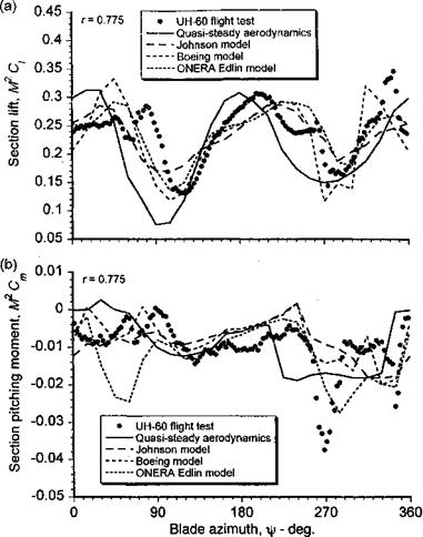
While it has been shown previously that the problem of dynamic stall can be conveniently dissected, analyzed, and modeled into more manageable subproblems, it is only when the elements of the submodels are combined into the full rotor simulation, including the rotor wake (inflow) and elastic blade dynamics, that the true benefits of any improved modeling efforts can be realized. Many authors have shown the effects of including representations of dynamic stall for rotor loads and aeroelastic predictions – see, for example, Tarzanin (1972), Gormont (1973), Johnson (1969, 1974), Carlson et al. (1974), Yen & Yuce (1992), and Nguyen & Johnson (1998). The predicte results are, however, somewhat mixed. Generally, by including unsteady aerodynamics and dynamic stall models, better predictions of the phasing of the unsteady airloads with respect to blade azimuth are obtained, along with correspondingly better predictions of overall rotor performance at the extremes of the flight envelope. However, the mixed results indicate that although it may be possible to reproduce the unsteady airloads on a 2-D section with most dynamic stall models, the prediction of in-flight airloads are much more difficult.

A representative example is shown in Fig. 9.18, which shows the lift (as M2Ci) and the pitching moment (as M2Cm) on a section of a rotor blade for a case where dynamic stall is present. The flight test results are taken from Bousman (1998), and the calculated results are taken from Nguyen & Johnson (1998). The unsteady airloads are computed with different dynamic stall models, while keeping fixed all other elements of the rotor model. As seen from Fig. 9.18, the agreement of the predictions with the measurements is indeed very mixed. The improvement over the use of quasi-steady aerodynamics is, however, clearly better, particularly in regard to the phase of the lift predictions. However, the predictions of the section pitching moment are probably less than what would be considered acceptable. For example, one of the models predicts large nose-down moments associated with dynamic stall at points over the disk where there is clearly no stall indicated in the flight test measurements. In other cases, stall is not predicted in the regions where flight tests clearly indicate otherwise.

The fault, however, lies not only with the stall models. The main difficulty in the rotor simulation is the proper calculation of the combination of AoA and Mach number that

Prediction of In-Flight Airloads

Figure 9.18 Predictions of in-flight dynamic stall airloads using semi-empirical stall mod­els. From Nguyen & Johnson (1998) and courtesy of Khanh Nguyen.

will delimit attached flow, and these calculations must properly include models of the rotor wake and blade motion in a fully coupled way. Because of the high AoA gradients that exist over the disk resulting from the wake inflow (see Fig. 3.30), the time steps (level of discretization) used in the rotor analysis can determine whether or not dynamic stall is initiated at all. In other words, it is possible to completely miss the stall event because the time step is too large to resolve the phenomenon. Furthermore, vortex shedding during dynamic stall occurs over relatively short time scales, generally of the order of 8 semi­chords of airfoil travel – see Galbraith et al. (1986). Therefore, if translated into an azimuth step for the rotor calculation, the azimuth step must be of the order of 2—5° to accurately represent dynamic stall. In the calculations shown in Fig. 9.18, a rotor azimuth step of 15° was used, which is probably too large to capture the correct details of stall onset and subsequent aft center of pressure movement resulting from dynamic stall. Therefore, this level of predictive capability is of great concern to the rotor analyst and shows that even if the ability to model 2-D (or even 3-D) unsteady airloads has been realized, the prediction of dynamic stall airloads in the rotor environment is still a problem that is at the limit of

current modeling capabilities. Equivalent arguments apply for phenomena such as blade vortex interaction (BVI), which occur over time scales of the order of 2-5 semi-chords of airfoil travel. In this case, the time (azimuth) step must be of the order of one degree or less to resolve both the wake and the BVI phenomena. Trading off predictive capability of the physics against computational cost is never a good situation, but this is slowly changing. The answer, however, does not just lie in the need for bigger and faster computers, but in better solution algorithms that have the accuracy and stability suitable for application to smaller spatial and temporal discretizations needed for high-fidelity helicopter rotor aerodynamic simulations.

Time-Varying Velocity Effects on Dynamic Stall

As discussed in Chapter 8, for a rotor in forward flight a blade element will en­counter a time-varying incident velocity and there will be additional unsteady aerodynamic effects to be considered. In nominally attached flow, these effects include more complicated circulatory contributions resulting from the nonuniform shed wake convection velocity, also with additional noncirculatory contributions. The problem of dynamic stall under these con­ditions is not completely understood but has been studied experimentally on 2-D oscillating airfoils by Pierce et al. (1978a, b), Maresca et al. (1981), and Favier et al. (1988). A time – varying onset velocity was obtained in the experiment of Pierce et al. by using choking of the upstream flow by means of rotating vanes and in the experiment of Maresca & Favier by means of fore-and-aft movement of the airfoil. In both experiments the AoA and free-stream velocity were varied harmonically with different relative phase angles.

Pierce et al. (1978a, b) have measured the airfoil pitching moment, with a view to under­standing the possible effects of varying free-stream velocity on the torsional aerodynamic damping at dynamic stall onset. The measurements in fully attached flow were found to be in good agreement with the “classical,” linearized unsteady thin airfoil models, as discussed in Chapter 8. In the vicinity of stall reduced aerodynamic damping was observed, although as shown previously, this is a characteristic found with steady onset flows and is related to the phasing of the dynamic stall events with respect to the forcing function (a, a, etc.).

In the other experiments by Maresca & Favier, measurements of the lift, drag, pitching moment, and chordwise pressure distribution have suggested some considerable influence of the varying free-stream velocity on the dynamic stall process. Depending on the phasing of the velocity variations with respect to the AoA, initiation of leading edge vortex shedding and the chordwise convection of this vortex appear to be different. Favier et al. (1988) measured a phase lead of the unsteady lift response for conditions with constant free- stream velocity, but these seem to be at variance both with other measurements for the same problem and also with linearized theory. In this regard, the various problems associated with the subscale Reynolds number simulation of the problem cannot be overlooked. The issue of time-varying incident flow velocity, unfortunately, has not yet been studied in detail using the various mathematical models of dynamic stall, and it would seem to be an ideal problem whose investigation is overdue. It would also seem that because of the difficulties in conducting experiments of this problem, it would form a good challenge for the various first – principles based CFD approaches to dynamic stall modeling currently under development (see Section 14.10.1)

Three-Dimensional Effects on Dynamic Stall

As discussed earlier in this chapter, in the rotor environment the problem of dy­namic stall must be considered as fully three dimensional. Stall will occur over different parts of the blade and at different blade azimuth angles, and needless to say, the resulting flow can be very complicated. Apart from the 3-D effects associated with swept flows, the
problem of 3-D unsteady separating flows are still poorly understood. As mentioned earlier, the various mathematical models used for dynamic stall prediction are still heavily empiri­cal, with reliance being placed almost exclusively on oscillating 2-D airfoils for formulation and validation purposes. It is only recently that attempts to validate these models has been made for 3-D dynamic stall problems, albeit these are still very much idealized problems compared to those found in the helicopter rotor environment.

Three-Dimensional Effects on Dynamic Stall
The problem of 3-D dynamic stall has been studied experimentally by Lorber et al. (1991), Lorber (1992), Pizialli (1994), and Berton et al. (2003a, b) and computationally by Spentzos et al. (2Q04). Lorber and Pizialli have used a cantilevered semi-span wing that was oscillated in AoA through stall and like the 2-D tests, was designed to simulate the variations in AoA encountered by a helicopter rotor blade. Miniature pressure transducers

Подпись:(3) 2

1.5 O*

1

0.5
0

Three-Dimensional Effects on Dynamic Stall

were distributed at various stations along the wing, and the measured pressures have been integrated to determine sectional lift, drag, and pitching moment. While Pizialli’s results are limited to a Mach number of 0.3, Lorber’s results cover a wider range of Mach number from 0.2 to 0.6 and also for wing sweep angles of 0, 15, and 30°. Berton et al. (2003a, b) and Spentzos et al. (2004) have also examined the dynamic stall of wings with finite span.

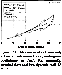
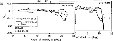
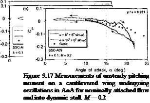
Representative results from the 3-D dynamic stall experiments of Lorber et al. (1991) are shown in Figs. 9.16 and 9.17. These results document the unsteady lift and pitching moment coefficients at five spanwise stations from near the mid-span out toward the tip of the wing. Results are shown for an oscillation below stall and for a typical case of dynamic stall at the same reduced frequency. The static measurements at each station of the wing are also shown for reference. For oscillations below stall, characteristic elliptical hysteresis loops are formed with no particularly unusual behavior compared to that expected from 2-D considerations. Notice, however, the gradual reduction in the average lift-curve – slope when moving outboard toward the tip, although this is a quasi-steady effect and would be predicted by any finite-wing model. The only exception is at the outermost wing station, where both the steady and unsteady lift and pitching moment hysteresis loops show a different characteristic, with a more nonlinear quasi-steady behavior. This is the influence of the tip vortex, which lies over the tip region and provides an element of
steady vortex induced lift. Other than for this one section of the wing, unsteady thin-airfoil theory, with the quasi-steady induced effects accounted for by a lifting-line or other finite – wing method, will provide a good approximation to the unsteady airloads – see Tan & Carr (1996).

The dynamic stall characteristics on 3-D finite wings are noted to be qualitatively similar to those found on oscillating 2-D airfoils. Figures 9.16 and 9.17 show that at the four inner stations, the airloads exhibit the lift overshoots, large nose-down pitching moments, and hysteresis effects that are characteristic of 2-D dynamic stall. Notice that when moving outboard from the innermost station the degree of dynamic stall penetration is reduced. Again, this is mainly a steady effect associated with the reduction in the effective quasi­steady AoA because of the induced effects from the tip vortex. In fact, the results appear qualitatively similar to those obtained with a reduction in the mean AoA in the 2-D case. While lift and pitching moment overshoots are also obtained at the outermost station, the results are less transient suggesting that leading edge vortex shedding does not occur. In fact, it would appear that the tip vortex alone dominates the flow field here and the AoA never becomes large enough to permit stall to occur in the normal sense.

Overall, the results in Figs. 9.16 and 9.17 indicate that if the wing aspect ratio is rela­tively high then the oscillating finite wing problem can still be considered nominally 2-D as far as dynamic stall is concerned, and 2-D models with appropriate allowance for the induced distribution of AoA associated with finite span should give at least engineering levels of predictive capability. This has been confirmed by results shown by Tan & Carr

(1996) , who compare results of the Pizialli experiments with a number of the better known semi-empirical dynamic stall models, some of which have been described previously. How­ever, this conclusion is based only on a limited validation study, and much further work still needs to be done to analyze the problem of 3-D dynamic stall if credible predictions of helicopter airloads are to be improved. The problems are further compounded by the centrifugal and Corriolis effects that are produced on the 3-D boundary layer develop­ments on rotating blades. The issues seem particularly acute on wind turbines, which often operate with substantial amounts of dynamic stall compared to a helicopter rotor – see Section 13.12.2.

Effect of Airfoil Shape on Dynamic Stall

McCroskey et al. (1980, 1982) have studied systematically the effects of airfoil shape on the dynamic stall characteristics of several different types of airfoils. Some of these airfoils are unsuitable for use on helicopters, but the results serve to bracket the effect of airfoil shape on the problem, albeit only at relatively low Mach numbers. Wilby (1984, 1996, 1998) reports another study of airfoil shape on the dynamic stall problem and over a much wider range of Mach numbers, including transonic flow. This author presents a tantalizing glimpse of a wealth of information on the dynamic stall problem; however, very little of these data have been formally published in the open literature. The datum airfoil used by McCroskey et al. (1980, 1982) was the ubiquitous NACA 0012, and results are summarized here for two other airfoils that are representative of modem rotor airfoils used on current production helicopters, namely the HH-02 airfoil (used on the AH-64 Apache) and the SC 1095 airfoil (used on the UH-60 Blackhawk). These are both cambered airfoils with approximately 9.5% thickness to chord ratios and can be considered

Подпись: rpnrpspntntivp r»f тг»Нрт hplimntpr airfnil Hp«ion« Thp Т-ГН-П9 Ьяс РПП«ІНРГЯЬ1У mnrp

leading edge camber than the SC1095, and it has the distinction of a large trailing-edge tab (see Fig. 7.24).

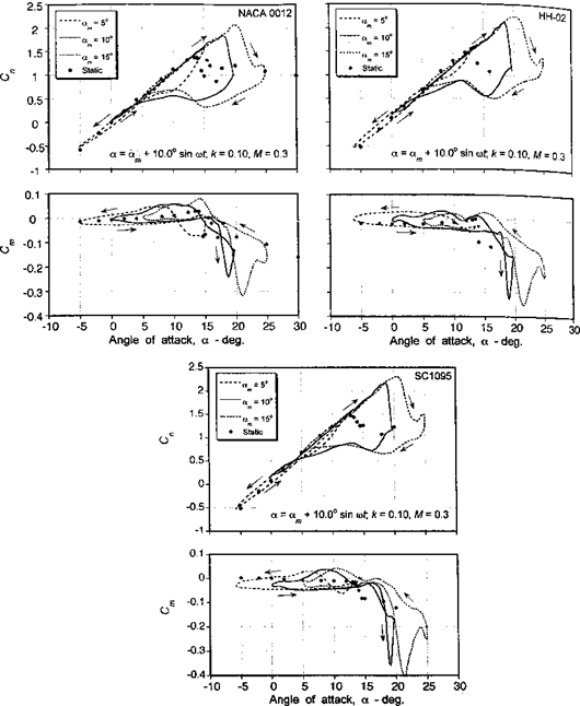
Some results showing the effects of airfoil shape on the dynamic stall airloads are summarized in Fig. 9.15, which shows the normal force and pitching moment coefficients for stall onset conditions through deep dynamic stall. In each case, the results are compared to the static airloads for that airfoil. The experimental data shown are for a free-stream Mach number of 0.3, which is the highest Mach number that was tested. At the lowest mean AoA of 5°, the maximum AoA becomes just large enough to initiate some minor leading edge separation, as evidenced by the distortion in the nominally elliptical hysteresis loops near

Подпись: -а Effect of Airfoil Shape on Dynamic Stall
the maximum AoA. All three airfoils exhibit a significant increase in maximum lift over the static values. It is clear, however, that the HH-02 and SC 1095 airfoils maintain attached flow to a slightly higher AoA, with correspondingly higher values of Cn, and, thereby, exhibit a slightly superior lifting performance to the NACA 0012. This is consistent with the static behavior of these types of airfoils (see also Section 7.9). Therefore, it can be concluded that

airfoils designed for high static lift capability should also exhibit a higher AoA capability before stall when operated under dynamic conditions.

The forces and pitching moments for a case of moderately strong dynamic stall, which occurs for am = 10°, are also shown in Fig. 9.15. Under these conditions, relatively strong leading edge vortex shedding is initiated and the characteristic lift overshoots and strong nose-down pitching moment behavior of dynamic stall are intensified. Considerable hys­teresis in the lift and pitching moment behavior is also present for these conditions. All three airfoils exhibit a qualitatively similar type of behavior, although it is apparent that there are measurable quantitative differences. The NACA 0012 exhibits moment stall at a lower AoA to either the HH-02 or the SC1095 airfoils, although the lift stall occurs at approximately the same AoA for all three airfoils. Both the NACA 0012 and the SC1095 airfoils exhibit a well-rounded moment break at the onset of dynamic stall in comparison to the HH-02, which has a very abrupt moment break. This suggests that some trailing edge flow separation is still present on the NACA 0012 and SC1095 airfoils prior to the onset of leading edge separation and dynamic stall. This also suggests that to some extent the static stall behavior of the airfoil is actually carried over into the dynamic stall regime. Both the HH-02 and SC 1095 airfoils exhibit a slightly greater maximum dynamic lift over the NACA 0012. Again, these static lift gains appear to be carried over somewhat into the dynamic regime. However, the NACA 0012 clearly exhibits a smaller peak value of (nose-down) pitching moment compared to the other two airfoils. This suggests a weaker shed leading edge vortex for the NACA 0012 airfoil.

As discussed in Chapter 7, the traditional approach in designing helicopter rotor airfoils is to maximize the quasi-steady lift and minimize the pitching moment. Little emphasis is usually placed on the consequences of the unsteady behavior of the airfoil. Figure 9.15 reinforces this point, where the oscillatory lift and pitching moment for a mean AoA of 15° indicate strong leading edge vortex shedding, producing significant increments in normal force and pitching moment coefficients. As for a mean AoA of 10°, all three airfoils exhibit a qualitatively similar type of dynamic stall behavior, with both the HH-02 and the SC 1095 airfoils exhibiting increased values of maximum dynamic lift over the NACA 0012. (It should also be noted that for each airfoil there is perhaps evidence of secondary vortex shedding near the maximum AoA, which manifest as smaller secondary peaks in the normal force and pitching moment.) It is significant that while under static conditions the SC 1095 exhibits a gain in maximum Cn of about 0.1 over the HH-02 airfoil, under these particular dynamic conditions there is almost no difference in maximum Cn between these two airfoils. This indicates that, whereas the maximum lift coefficient may be a useful measure of airfoil performance under static conditions, this does not necessarily appear to be an indication of the dynamic lift capability of the airfoil. Also, although the HH-02 and the SC 1095 airfoils give approximately the same value of maximum dynamic lift, the maximum nose-down pitching moment is clearly greater for the SC 1095. This is despite the fact that the HH-02 has a higher zero-lift pitching moment under quasi-steady conditions. Therefore, like the lift coefficient, the design of airfoils for low static pitching moments does not necessarily guarantee that low dynamic pitching moments will also be produced.

Effects of Sweep Angle on Dynamic Stall

The local sweep or yaw angle of the flow to a blade element on a helicopter rotor in forward flight can be significant. The radial component of the velocity relative to the leading edge of the blade is the source of this sweep angle, as shown in Fig. 9.11. The sweep angle, A, is defined in terms of the normal and radial velocity components Ut and Ur, respectively, by

л(r, fr) = tan-1 (= tan-1 ( . (9.6)

Ut ) r + [Msmf J

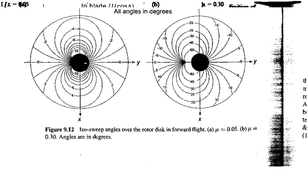
Examples of the iso-sweep angle distribution over the rotor disk are shown in Fig. 9.12 for advance ratios of 0.05 and 0.3. At the higher advance ratios, the sweep angles can exceed 30° over some parts of the disk. Overall they clearly become significant enough that their effects would need to be assessed experimentally by means of wind tunnel tests; any effects on the aerodynamics so produced will also need to be represented and properly integrated within a model of dynamic stall/

Effects of Sweep Angle on Dynamic Stall
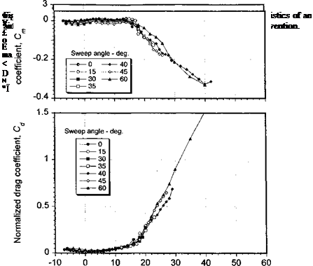
In the classical blade element theory, we usually neglect the effect of sweep on the lift, drag, and pitching moment. This is in accordance with the independence principle of sweep – see Jones & Cohen (1957). However, when an airfoil is operated at high AoA near stall this may not be a valid assumption. For example, the effect of sweep angle on the static lift characteristics of a swept 2-D airfoil is shown in Fig. 9.13. The results are based on the measurements of Purser & Spearman (1951) and are presented in the conventional blade element format – that is, in terms of AoA and velocities normal to the leading edge of

Effects of Sweep Angle on Dynamic Stall

the airfoil section. When the data are presented this way, the results for the lift, pitching moment, and drag show a close correlation and confirm that, at least in the attached flow regime, the independence principle is a valid assumption. However, notice that in the high AoA region a much higher lift coefficient is obtained for the larger sweep angles. This is because of favorable effects on the spanwise development of the boundary layer, which tend to delay the onset of flow separation on the wing to a higher AoA – see also Dwyer & McCroskey (1971). Similar results have been found experimentally by St. Hillaire et al. (1979) and St. Hillaire & Carta (1979,1983a, b).

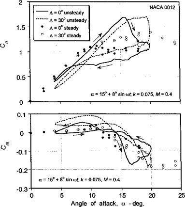
The upshot of these observations is that if these sweep effects are to be found on the rotor then they will tend to delay the onset of stall on the rotor to higher values of thrust, a result observed experimentally. Various earlier studies of the problem, including those of Harris (1966) and Gormont (1973), suggest that improvements in rotor thrust prediction can be obtained by including a static stall model that accounts for a delayed stall AoA and higher maximum lift as a function of sweep angle. However, it must be remembered that when stall occurs on the rotor in forward flight, the stall is actually dynamic in nature. To assess this problem, a series of experiments have been conducted by St. Hillaire & Carta (1979,1983a) where a NACA 0012 airfoil at a constant sweep angle of 30° was used.

These oscillating airfoil tests were perfoimcd at Mach numucis ui O. j and 0.4 and Reynolds numbers that are nominally full-scale rotor values. The measurements were determined by the integration of sectional pressures measured by pressure transducers distributed about a section at the mid-span of the model. Leishman (1989) has also conducted an analysis of these data. It appears that for fully attached unsteady flows the independence principle also applies. Any unsteady effects associated with sweep are small in the attached flow regime – probably smaller than uncertainties associated with the measurements themselves. However, in the dynamic stall regime, there are other characteristics of swept flow that are worthy of consideration.

Effects of Sweep Angle on Dynamic Stall

Figure 9.14 Behavior of the dynamic lift and pitching moment for a pitch oscillation in swept and unswept flow.

Figure 9.14 shows a typical behavior of the lift and pitching moment coefficients in the dynamic stall regime for a pitch oscillation. A feature of these dynamic stall results is that compared with the static case where approximately a 20% higher maximum Cn was attained for A = 30°, the unsteady case shows a delay in dynamic lift stall to a higher AoA, but not to a significantly higher maximum value of lift. Also, for A = 30° somewhat narrower lift hysteresis loops are produced, and the mean value of lift is somewhat higher. Thus, it appears that the effects of sweep on the rotor may serve to provide an overall increase in average rotor thrust compared to predictions obtained when sweep effects are not included. It should be noted,, however, that the expected increase in thrust is not because of higher

Подпись: зіпре nfKnt cimnlv Краяне** thf* тмп vain*» nf tfiF* lift ie biahnr Thf* Hivprapnrp in

the pitching moment (moment stall) occurs at the same nominal value of AoA for both the A = 0° and A = 30° cases. However, the slope of the pitching moment curve during the next part of the cycle is clearly less for the A =30° case. Also, the minimum pitching moment is reached at a higher AoA. This suggests that the delay in dynamic lift stall to a higher AoA in swept flow is due, in part, to a lower velocity at which the shed leading edge vortex is convected over the chord. The comprehensive analysis performed on the airfoil pressure time histories by St. Hillaire & Carta (1983a) also supports this observation. In light of these results, it would appear that from a modeling perspective simple corrections to the stall AoA based on steady flow observations, such as suggested by Harris (1966), may give the desired effect on rotor performance predictions, but for the wrong underlying reasons. This problem, like several others in rotating-wing aerodynamics, illustrates the difficulties in simply extrapolating observations of quasi-2-D steady airfoil behavior to the complicated 3-D flow environment found on rotors.