Category Principles of Helicopter Aerodynamics Second Edition

Physical Size

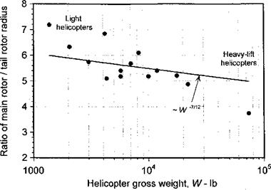
Consider the physical characteristics of typical tail rotors on production heli­copters, as listed in the appendix. A comparison of the size of the tail rotor to the main rotor shows that it is roughly one sixth the diameter of the main rotor. Because the ratio decreases with gross weight, the size of the tail rotor grows more rapidly than the size of the main rotor with increasing gross weight, as shown in Fig. 6.29. Note that for machines with fenestrons, the size of the fenestron can be much smaller than that of a conventional tail rotor. Again, the trends (for conventional tail rotors) can be explained with the aid of the square-cube law. It has been shown previously that the main rotor power (or torque) required is oc W3/2. Also, because the size of the helicopter (and length of the tail moment arm) grows with W1/3 so the anti-torque force requirement should be a W7/6. Because tail rotor disk loading remains relatively independent of helicopter gross weight (for good efficiency), the size of the tail rotor should be oc W~7^12. This trend is in general agreement with the data shown in Fig. 6.29. Note also that the tail rotor tip speed is approximately the same as the main rotor tip speed. This means that the rotational speeds of tail rotors are roughly six times the main rotor frequency, and this has particularly important consequences on rotor noise levels. While the noise energy produced by the tail rotor is only a fraction of that produced by the main rotor, the higher frequencies generated by the tail rotor can be more discernible to the human ear (see Section 8.19).

Design of Tail Rotors

The vast majority of helicopters in production are of the single main rotor with tail rotor configuration. The primary purpose of the tail rotor is threefold. First, the tail rotor provides an anti-torque force to counter the torque reaction of the main rotor on the fuselage. Second, the tail rotor gives yaw stability and provides the pilot with directional control about the yaw axis. Third, the aerodynamics of the tail rotor provide the helicopter with a significant weathercock stability. For example, if the helicopter is yawed nose-left, then the tail rotor will experience an effective climb. If the collective pitch is held constant, then this will result in a decrease of thrust (a result of the higher inflow) and a restoring moment about the yawing axis. Similarly, if the helicopter yaws nose-right, the tail rotor experiences an effective descent, with an increase in thrust, and again, a restoring moment is produced. This weathercock stability is a useful characteristic of tail rotors, but it can also make helicopters less maneuverable.

The tail rotor has to operate in a relatively complex aerodynamic environment and its operation is affected by the main rotor wake, the main rotor hub and the empennage. How­ever, to be effective it must produce thrust with the relative flow coming from essentially any direction. This means that the aerodynamic design requirements for the tail rotor are different in some respects from those of the main rotor. For these reasons, it is known to be difficult to design a tail rotor that will meet all the various interdependent aerodynamic,

Design of Tail Rotors

Figure 6.29 General trends of main rotor size to tail rotor size versus helicopter gross

weight.

control, stability, weight, and structural requirements. See Lynn (1970), Cook (1978), Byham (1990), and Newman (1994) for a detailed overview of tail rotor design issues.

Role of Wind Tfinnels in Aerodynamic Design

Wind tunnel testing of subscale rotors and airframes is an important technique for estimating the performance of full-size helicopters. The various techniques are discussed by Harris (1973) and Philippe (1990). Wind tunnel tests allow good estimates of rotor thrust and airframe drag and also help to design out complicated effects prior to first flight, including any adverse rotor-airframe interactional effects – see Chapter 11. To reduce Reynolds number uncertainties and minimize risk, large – or full-scale testing is desirable – see also Section 7.3.4. While the wind tunnel testing of a full-scale rotor or a complete helicopter is an enormously expensive and time consuming undertaking, it can be much less expensive than remedying a persistent problem after the helicopter has flown. Wind tunnel testing with close to full-scale rotors gives the analyst the opportunity to measure results exactly as they would be found on the actual helicopter, without the uncertainties of Reynolds number or other issues that would be apparent on subscale models. Yet very few wind tunnels in the world are capable of full-scale or large subscale rotor experiments. Full-scale rotors are routinely tested on hover towers by helicopter manufacturers, but this gives only limited knowledge of their overall performance.

The need for measurements of rotor thrust and power is essential in any model test, these usually being obtained using strain-gauge balances. The use of blade and airframe instru­mentation for on – and off-surface measurements are usually a goal in either hover or wind tunnel testing, although such data are not always available simultaneously from any one tunnel entry. The issues of repeatability of the test conditions and rotor operating state then become a concern. The difficulties in obtaining off-surface measurements in the wake of the rotor cannot be underestimated (see Chapter 10), and for comprehensive tests on large or full-scale rotors, this often requires an international effort by specialists from several organizations. As a consequence, most helicopter rotor and rotor-airframe testing has been done at a smaller scale, which may range from 1/4 to 1/8 scale. Such tests are often on simpler and more generic airframe configurations, perhaps with aeroelastically stiff (rigid) blades to better isolate specific interactional aerodynamic phenomena – see Chapter 11. This gives the analyst the best opportunity to precisely define the geometry of the problem and to study the flow physics of specific phenomena with greater confidence. These tests can provide the analyst with a comprehensive data suite of on – and off-surface measurements (along with estimates of tunnel wall interference effects), and so are ideally suited for the validation of computational models of the flow field. Unfortunately, few tests have pro­vided coincident measurements of on-surface loads and off-surface flow properties, and the lack of such data continues to impede the validation of computational aerodynamic models.

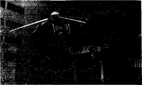
The testing of geometrically and aeroelastically scaled rotor models gives much informa­tion about the actual capabilities of the full-scale rotor system. Combined with geometrically scaled airframe models such as that shown in Fig. 6.28, the net system performance can be measured to a high level of fidelity and the measurements used confidently to validate various levels of performance predictions. Despite the enormous costs, pressure measure­ments on the blade surface are extremely useful for the validation of comprehensive rotor analyses. This helps gain better confidence levels in these analyses for use in the design of future rotors. However, the complications of elastic blade deformations on the full-size helicopter makes it difficult to isolate specific aerodynamic phenomena, and such tests are

Role of Wind Tfinnels in Aerodynamic Design

Figure 6.28 A geometrically scaled rotor and airframe of the NH-90 helicopter tested in a large wind tunnel.

less useful for generating high-fidelity measurements that can be used for the validation of flow models. As better Navier-Stokes-based CFD methods and turbulence models become increasingly capable and reliable, the role of wind tunnel testing on larger scale rotor con­figurations must clearly shift back toward the generation of high-fidelity measurements on simpler configurations but at close to full-scale flight Reynolds numbers. In this regard, the closure (or constant threat of) of large subsonic wind tunnels suitable for helicopter studies continues to be a major concern to both the research and manufacturing community.

Vertical Stabilizer

The primary purpose of a vertical stabilizer or fin is to provide stability in yaw. While the tail rotor itself provides considerable yaw stability, the vertical stabilizer may also be required to provide sufficient aerodynamic side-force to offset the tail rotor thrust in forward flight and to provide sufficient anti-torque to allow continued flight in the event of the loss of the tail rotor – see Horst & Reschak (1975). This side-force can be provided by using an airfoil section with a relatively large amount of camber. Alleviating the tail rotor thrust in high-speed flight by means of a side force on the fin is usually desirable to minimize tail rotor flapping and cyclic loads and to maximize component fatigue life. With sufficient forward speed and some side-slip angle, the side-force can be great enough to allow continued flight without the tail rotor, although this flight condition is difficult to achieve in practice.

The vertical stabilizer also forms a structural mount for the tail rotor. Because the flows will strongly interact, the tail rotor can be considered to be an integral part of the fin and empennage assembly. The size of the vertical stabilizer directly and adversely affects tail rotor performance. A smaller stabilizer will reduce the adverse effects on tail rotor efficiency, but this must be balanced against the effects on yaw stability and other design requirements including sideward flight. Because of the need for side forces on the fin to be low when the helicopter is operating in hovering flight with a crosswind, the trailing edge of the fin may often be blunt because this tends to help reduce adverse fin forces at large angles of

attack. The special complications associated with the design of the tail rotor itself means the aerodynamics of the tail rotor and the interactions with the fin must be discussed separately – see Section 6.9.

Empennage Design

The empennage on a helicopter consists of the vertical and horizontal stabilizer

япН гр. іяїрН Ґпяр. іясгр. ctnirhirp А сїяЬііЇург іс cimnlv я cnrfarp їЬяї nrnrlnrfvc ял flprnHv-

———————– X – ~ «v*****^ v.»v*vriv««vvU

namic lifting force (positive or negative). The primary purpose of a stabilizer is to enhance stability about a particular axis (pitch, yaw), although there are secondary aerodynamic characteristics of stabilizers that are important design considerations for helicopters. These problems are often associated with component interaction aerodynamics – see Chapter 11.

6.7.1 Horizontal Stabilizer

The primary purpose of a horizontal stabilizer is to give the helicopter stability in pitch. Both the helicopter rotor and its fuselage have an inherent negative stability derivative in pitch and the stabilizer helps to give the helicopter better overall handling qualities. The fuselage itself has a powerful negative stability because of the typically large surface area of the airframe forward of the center of gravity – see Prouty (1985). The selection of the size and position of the horizontal stabilizer on the tail has proven to be one of the most difficult challenges facing helicopter designers. In addition to aerodynamic, structural, weight and stability and control trade-offs, there are important aerodynamic interactional effects be­tween the rotor wake and the tail region – see Section 11.3.1.

Prouty & Amer (1982) describe how there are basically three types of horizontal stabilizer designs used on helicopters: a forward mounted stabilizer, an aft mounted low stabilizer, and a T-tail design. Using a forward fixed stabilizer will generally avoid any sudden changes in download caused by wake impingement because it will remain inside the rotor wake boundary from hover up until a fairly high forward flight speed is reached. Many Bell heli­copter designs use this forward stabilizer position. However, because the reduced moment arm, the surface must be larger (and heavier) compared to a stabilizer mounted further back along the tailboom. The stabilizer, however, may have a capability of being used for trim augmentation in that the pitch angle may be linked into the longitudinal cyclic. In hovering flight the rotor wake produces a vertical download on forward mounted horizontal stabi­lizers, which usually represents a significant performance penalty. The Bell designs also use an inverted airfoil for the stabilizer, which creates a download in forward flight to keep the fuselage at an angle of attack for lowest parasitic drag. It is also designed to stall when the helicopter is in steep autorotation to avoid producing an upthrust and an undesirable nose-down pitching moment on the fuselage.

A stabilizer that is mounted low down near the end of the tail has good structural efficiency, with all the loads being carried directly into the tail boom. However, this stabilizer design tends to produce interactional aerodynamic issues and trim during transition from low-speed flight into hover or vice versa, where the main rotor wake may suddenly move forward over the empennage location and so produce a nose-down pitching moment on the helicopter – see Section 11.3.1. Also, the unsteady separated flow from the upper fuselage and rotor hub tends to reduce the efficiency of this type of stabilizer design so that the lifting area needs to be greater than for one that could be located away from the wake. On military helicopters, clearance issues between the tail and the ground may be important and can preclude this particular design choice. Nevertheless, as evidenced by the large number of helicopters with this low mounted horizontal stabilizer configuration, it is a popular design choice for small to medium size helicopters.

In the T-tail design, the horizontal stabilizer is mounted at the top of the vertical fin. This moves the stabilizer away from the rotor wake for most flight conditions, and so it can be smaller in area to give the same overall stability. However, the design is structurally inefficient because of the higher overall weight of the vertical fin required to carry the stabilizer loads, and also because of various low-frequency structural vibration modes that can be excited by the main and/or tail rotors. On a low or forward set stabilizer, it may be necessary to have different incidence (pitch) settings for the port and starboard sides to account for the gradients in downwash in the rotor wake. With a T-tail design, there are often twisting moments that may limit the maximum area of the stabilizer. Often a compromise is drawn by using a stabilizer mounted to only one side of the fin, such as used on many of the Sikorsky machines. See Prouty & Amer (1982), Prouty (1983), Hansen (1988), and Main & Mussi (1990) for further information on stabilizer design.

A stabilator is a stabilizer that has a variable incidence (pitch) capability. It can help give better overall handling qualities over a wider range of flight conditions than is possible with a stabilizer of fixed pitch, including hovering flight. The stabilator is set to large positive pitch angles in hovering flight to help reduce download effects and is reduced to low pitch values in cruise flight. The pitch angle is set automatically by a flight control computer using airspeed and other measurements, although manual override can be used to give the pilot control of the stabilator below certain airspeeds. A stabilator is mechanically relatively complicated compared to a stabilizer because it requires a pitch change mechanism, and is also a structurally inefficient design choice because of its higher weight. However, some­times it can be the best choice to meet the demanding flight envelope of military helicopters. For example, a stabilator design is used on both the AH-64 and UH-60 helicopters.

Fuselage Side-Force

During hovering flight, the tail rotor provides the anti-torque thrust to maintain yaw equilibrium. However, in sideward flight or when hovering over a fixed point above the ground in a cross wind, an aerodynamic side-force will also be produced on the fuselage. For most helicopters this side-force is small enough to have a minimal impact on the handling qualities and operational envelope. For a rotor turning in the conventional direction (counterclockwise when viewed from above), the aerodynamic side-force on the fuselage and tail boom will be opposite to the direction of the tail rotor thrust when the helicopter is in starboard sideward flight or has a starboard crosswind component. On some helicopters this effect can affect directional (yaw) control and in some cases may even limit the operational flight envelope – see Amer & Gessow (1955) for the first study. In particular, this can be an issue on military helicopters, which must often demonstrate high-speed sideward flight capability for combat tactics, or for naval helicopters in particular, which must often operate in confined locations in gusty crosswind conditions.

Fuselage Side-Force

The aerodynamic side-force on the fuselage is found to be accentuated by certain tail boom shapes, which can produce a sizable circulatory lift force in the direction opposite to the anti-torque requirement when the sideward velocity is combined with the main rotor downwash. To counter this undesirable effect, Brocklehurst (1985) and Wilson et al. (1988)

have suggested the use of a strake that runs longitudinally along the one side (usually the port side) of the tail boom – see Section 11.2.4 for a detailed discussion. This strake forces the flow to separate, spoiling the aerodynamic side-force on the tail boom, thereby restoring or improving the normal operational flight envelope of the helicopter. See also Kelly et al.

(1993) .

Vertical Drag Recovery

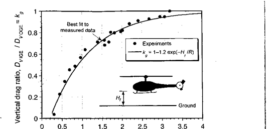
When determining in ground effect (IGE) hover capability of the helicopter, the vertical fuselage drag must be corrected to account for a favorable effect that occurs in this regime. This is referred to as vertical drag recovery or airframe download recovery and offsets the download obtained on the fuselage from the rotor when the helicopter is hovering very near to the ground. This behavior results from a change in static pressure in the wake below the airframe. Measured results documenting this phenomenon are given

Fuselage height above ground, Hf /R

by Fradenburgh (1972) and Stepniewski & Keys (1984). The decrease in effective fuselage vertical drag is found to be significant for hovering heights of less than one rotor diameter. The results of measurements are shown in Fig. 6.27 in terms of the download ratio in ground effect to that out of ground effect (OGE). It is apparent that the behavior can be modeled approximately by

Rhge. = kg^i_ 1.22 exp {-Hf/R) for Hf/R > 0.25. (6.36)

Dvqge

Vertical Drag and Download Penalty

It is normally assumed that the total thrust, T, required by the main rotor is equal to the weight of the helicopter, W. However, there is usually an extra increment in power required because of the download or vertical drag, Dv, on the helicopter fuselage that results from the action of the rotor slipstream velocity (i. e., now the rotor thrust will be T+AT = W+Dv). See Wilson (1975) for a good summary of the basic problem. Typically, the vertical download on the fuselage can be up to 5% of the gross takeoff weight, but it
can be much higher for some rotorcraft designs such as compounds or tilt-rotors that have large wings situated in the downwash field below the rotor. In its simplest form, the vertical drag can be accounted for by assuming an equivalent drag area fv or a drag coefficient C0u based on a reference area, say Sref. This means that the extra rotor thrust to overcome this drag will be

AT = DV= pv2f„, (6-29)

where v is the average velocity in the rotor slipstream.

In the first instance, the simple momentum theory can be used to estimate v. It is known that the rotor wake contracts very rapidly below the rotor, so that the airframe can be assumed to operate in the fully developed vena contracta; in the hover condition this velocity is twice the induced velocity at the disk. In a vertical climb, the induced velocity at the rotor will be given using Eq. 5.15, which for normal rates of climb is approximately

— = 1 – (6.30)

vh 2vh

Because the wake velocity v is given by v — Vc + 2u,-, then using Eq. 6.30 it is apparent that v = 2 Vh, that is, v is independent of climb velocity Vc. This means that the rotor thrust will be

T = W + DV = W+ l-pv2f„ = W + Ipvlf, = W + T (A) . (6.31)

Rearranging and solving for the rotor thrust T gives

Подпись:T = (-^______ Ї___ V

1 – fv/A) 1 — SVef CdJAJ

Подпись: Vk IVC / w ■ 1 - fv/A  ~2~ ~y 2pA( — fv/A) Подпись: + EQ, Подпись: (6.33)

From this result, the net rotor power requirements can be easily calculated using

which is valid for low to moderate rates of climb, assuming the validity of Eq. 6.30. It will be apparent, fortunately, that because /„/A < 0.1 then the airframe drag makes only a modest additional contribution to the total power requirements in climbing flight.

Because of the bluff-body nature of the flow about the fuselage, estimates of the vertical drag can only be reliably obtained from wind tunnel testing of isolated fuselage models. Precautions should be taken to properly represent the nonuniformity of the rotor downwash, as well as Reynolds number effects on the fuselage, the latter which can be difficult to

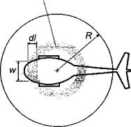
In the second instance the vertical drag on the fuselage can be calculated by estimating the drag coefficient of individual 2-D fuselage cross sections (i. e., a strip approach), as shown schematically in Fig. 6.26, which is suggested by Stepniewski & Keys (1984). The vertical drag of the entire fuselage can then be obtained by successively testing 2-D cross sections of the fuselage to determine the pressure distributions and then finding the net drag on the fuselage by summation. For example, the incremental vertical drag on any one segment of the fuselage of length dl and width w will be

Подпись: (6.34)dDv = ^pv2CDvw dl,

2.

where v is the local downwash velocity (from the fully developed rotor wake) at the element and Cdv is the drag coefficient. The net vertical drag will be given by

Vertical Drag and Download PenaltyПодпись:Подпись:Vertical Drag and Download Penalty

Vertical Drag and Download Penalty

(6.35)

where it is recognized that Cov and v will vary between cross sections. Generally, it is found that helicopter fuselage cross-sectional drag coefficients average out at about 0.5, although the addition of sponsons or stub-wings can increase the drag coefficients to over unity. Wilson & Kelly (1983, 1986) give results for a variety of fuselage cross-sectional shapes, which have been estimated from wind tunnel tests. Drag coefficients for various other bluff – body shapes resembling fuselage cross sections can be found in Delany & Sorensen (1953) and Hoemer (1965).

Note that the strip method of fuselage drag estimation requires an estimate for distribution of the induced velocity in the wake below the rotor. A good first estimate can be made by means of the BEMT discussed previously in Chapter 3. However, because the fuselage also influences the rotor in a reciprocal way, accurate estimates of the interference effects on v are difficult to obtain. The effect of the fuselage is also known to affect the rotor performance, increasing the thrust as the fuselage is brought closer to the rotor – see for example Sheridan (1978), Sheridan & Smith (1979), and Fradenburgh (1972). Because of these effects, and the fact that 3-D effects have also been neglected, the strip method described above tends to be rather crude, at least in theory. Yet, in practice the method has been shown to give fairly reliable estimates of the extra rotor thrust required to overcome fuselage drag in climbing flight.

Fuselage Aerodynamic Design Issues

The fuselage is the largest airframe component on a helicopter, so its aerodynamic characteristics will have a significant impact on the performance of the helicopter as a whole. Functional constraints such as the need for rear loading doors means that the shapes that are typical of helicopter fuselage designs are often prone to flow separation and high drag. In addition, the airframe often operates in the main rotor wake, which changes the aerodynamic characteristics compared to those obtained without the rotor. These effects make the understanding and prediction of airframe aerodynamics extremely complicated, to the point that the whole of Chapter 11 is devoted to the subject.

6.6.1 Fuselage Drag

The parasitic drag of the fuselage affects cruise speed and fuel consumption of the helicopter. Williams & Montana (1975) and Keys & Wiesner (1975) have emphasized the need for low fuselage drag in the design of helicopters for improved performance. The drag of a helicopter fuselage may be up to one order of magnitude higher than that of a fixed-wing aircraft of the same gross weight. One reason is because of the rotor shaft, hub, and blade attachments, which may account for 30% or more of the total fuselage drag – see Sheehy & Clark (1975) and Sheehy (1977). Another major contributor is the fuselage after-body or bluff-body drag, which may account for 20% of the total fuselage drag. Drag is also caused by flow separation in the region where the main fuselage tapers to the tail boom. Sedden (1982) has shown that large drag penalties result when using fuselage shapes with large rear fuselage upsweep angles, because these can promote flow separation and

Fuselage Aerodynamic Design Issues

the formation of two strong trailing vortices. See also Epstein et al. (1994) for details of this phenomenon.

There are, however, many constraints that can limit the design of the fuselage shape and consequently the lowest possible drag of the fuselage. Much depends on the operational needs for the machine. For example, as shown in Fig. 6.24 an executive transport helicopter can be designed to have a more streamlined fuselage compared to a utility helicopter, which may need to have a rear access door. In either case, it is found that the fuselage shape should be more circular than square to keep drag as low as possible. Using a fairing over the top of the fuselage can help reduce drag from the main rotor shaft and control linkages. See also Montana (1975,1976). Replacing the skids with a retractable undercarriage can reduce drag considerably. However, a fixed wheeled undercarriage will have higher drag than skids. The use of active flow separation control concepts seems a prime candidate for a future means of fuselage drag reduction – see Section 9.12.

In view of the complicated interacting viscous dominated flows that can exist over helicopter fuselages, predictive capabilities for pressure and skin friction drag are not yet mature. Current capabilities for design are based on synthesis of component drag using experimental data or by using a combination of experimental data and potential flow theory. Classical panel methods have found considerable use in routine helicopter fuselage design – see Section 14.7 for details. These methods are based on the assumption of small disturbance potential flow, with the basic approach being described by Hess (1990). A modem treatment

Fuselage Aerodynamic Design Issues

Plotkin (1991). Large computer codes that use panel methods are commercially available and are in widespread use in the helicopter industry. Sophisticated computational fluid dynamics methods such as Navier-Stokes and Reynolds-Averaged Navier-Stokes (RANS) are still in the development stage – see Section 14.2.1. Even if enormous computer memory and storage requirements can be overcome, they are relatively far from being practical for use in routine helicopter fuselage design studies. Another problem with Navier-Stokes methods is the efficient generation of grids, and especially the proper coupling of structured and unstructured grids. However, rapid progress in grid generation techniques and solution

algorithms is being made. See, for example, Berry et al. (1994), Chaffin & Berry (1994), Duque & Dimanlig (1994), and Duque (1994).

To supplement numerical predictions of fuselage aerodynamics, semi-empirical drag prediction methods are in widespread use in the helicopter industry. Based on component testing in the wind tunnel, and with some additional engineering judgment, these approaches can give very reliable estimates of fuselage drag. An estimate of the fuselage parasitic equivalent wetted or flat-plate area, / (introduced in Section 5.4.5), can be determined from a knowledge of the drag coefficients of the various components that make up the helicopter using an equation of the form

Подпись: П (6.28)

where Sn is the area on which the definition of Co is based. This may be either the wetted area or the projected frontal area of the component. Initial drag estimates will assume no mutual interference effects from individual components, but despite this approximation the approach is found to give a reasonable initial estimation for the fuselage drag. More refined values of / are obtained by component testing of isolated fuselage and rotor/fuselage models in the wind tunnel – see, for example, Bosco (1972), Wilson (1984), Philippe et al. (1985), and Wilson (1990). Component interference effects can then be incorporated into the drag estimate. Further refinements need actual flight tests because wind tunnel models cannot simulate accurately the effects of full-scale Reynolds numbers, or drag producing details such as antennas, leakage through doors, and other gaps. In this case, estimates of drag are derived indirectly from rotor power measurements. The whole process, although somewhat empirical, gives quite reliable estimates of the parasitic drag.

An analysis of the individual items contributing to the parasitic drag of a typical helicopter is given in Table 6.1. These results are not for any one helicopter design per se and must be considered only as representative. It will be apparent that a major source of the overall drag is the rotor hub and blade attachments, which may account for up to 30-50% of the total parasite drag on fully articulated rotor blade designs. Sheehy & Clark (1975), Sheehy (1977), Sedden (1979), and Prouty (1986) give a good summary of various sources of published rotor hub drag data. Considerable turbulence may also be produced behind the hub, which

Table 6.1. Typical Breakdown of Parasitic Drag

Components of a Representative Helicopter.

Afte r Prouty (1986)

Подпись:Подпись: 30 6 35 4 6 4 1 Подпись:Component

Fuselage

Nacelles

Rotor hub & shaft Tail rotor hub Main landing gear Tail landing gear Horizontal tail Vertical tail

Rotor/fuselage interference Exhaust system Miscellaneous

Fuselage Aerodynamic Design Issues

Figure 6.25 Equivalent flat-plate (wetted) areas for a selection of helicopter designs.

can have an influence on the magnitude and frequency of the airloads produced on the tail boom and empennage; see Berry (1997) for a discussion of hub turbulence measurements. Further discussion of this important issue is made in Chapter 11. Streamlining the fuselage on the top of the airframe near the hub can help reduce the drag of the rotor shaft, the exposed controls, and the hub. However, it is only with the use of modem hingeless or bearingless rotors that hub drag reductions are possible, with values of f j A for a bearingless rotor being about half those of an articulated design. Cler (1989) describes a fully faired hub design, although this is impractical for most helicopters.

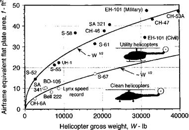
The equivalent total flat-plate areas of helicopter airframes range from less than 10 ft2 (0.93 m2) on smaller helicopters to as much as 50 ft2 (4.65 m2) on large utility helicopter designs, as shown in Fig. 6.25. Heavy-lift crane designs may have twice these values (>100 ft2 or 9.3 m2 being typical). The measured data have been obtained from a variety of sources, including Rosenstein & Stanzione (1981). The results suggest that values of f/A typically will fall between 0.004 for clean helicopter designs and up to 0.025 for first-generation or heavy-lift transport helicopters. Again, notice that the drag curves are approximately proportional to (weight)1/2, which follows the “square-cube” law mentioned previously. Obviously, the addition of external hardware or stores on military helicopters tends to dramatically increase its equivalent wetted area, thereby significantly increasing power required and reducing forward flight performance. Conversely, a general drag clean up of the airframe can result in substantial increases in climb and forward flight speed capability, as well as in reduced fuel bum and improved overall operational economics.

Case Study: The BERP Rotor

The British Experimental Rotor Program (BERP) blade has been alluded to pre­viously and is worthy of special consideration because its design encompasses some of

Case Study: The BERP Rotor

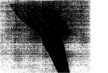
Figure 6.21 Photograph of the BERP blade as used on the Westland Lynx. (Courtesy of Westland-Agusta.)

the issues discussed in the previous section. The BERP rotor was designed specifically to meet the conflicting aerodynamic requirements of the advancing and retreating blade conditions, either of which can limit the C^/Cq of the blades and the performance of the rotor in high-speed forward flight. The technical details of the BERP research program are described by Perry (1987), Perry et al. (1998), and Wilby (1998). This research paid off in 1986 when a Westland Lynx attained the world absolute speed record for a conventional helicopter.

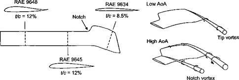
As shown in Fig. 6.21, the BERP rotor blade is distinctive because of its unique tip shape. However, the aerodynamic improvements shown with the BERP rotor are the result of several innovations in both airfoil design and tip shape design. The BERP blade uses a number of high performance airfoils based on the RAE family (see Fig. 6.22). The main lifting airfoil is the RAE 9645, which is located on the blade from 65 to 85% radius. This airfoil has a maximum lift coefficient of about 1.55, which is high compared to even second- generation helicopter airfoil sections – see Dadone (1976) and Wilby (1998). However, this high lift coefficient is obtained at the expense of higher pitching moments. These pitching

Case Study: The BERP Rotor

Figure 6.22 Distribution of airfoil sections on the BERP blade and high angle of attack performance. Adapted from Perry (1987).

moments are offset by the RAE 9648 airfoil, which is reflexed and located inboard of 65% radius where the demands of high maximum lift are not so important. The tip region uses the RAE 9634 airfoil, which has a relatively low thickness-to-chord ratio to give a high drag divergence Mach number. The RAE 9634 airfoil is also cambered in such a way as to give a weak shock wave and low pitching moments.

A distinctive feature of the BERP blade is the use of high sweepback over the tip region, which as mentioned previously, is an effective means of reducing compressibility effects and delaying their effects on the rotor to a higher advance ratio. On the BERP blade a progressively increasing sweepback angle is used over the outboard 16% of blade radius. Because the Mach number varies linearly along the blade, the amount of sweep that is necessary can be minimized by keeping the Mach number normal to the leading edge approximately constant – see Section 6.4.6. What is different for the BERP blade is that the area distribution in the tip region is configured to ensure that the center of lift is located close to the elastic axis of the blade. This is done primarily by offsetting the location of the local 1/4-chord axis forward starting at 86% radius. This offset also produces a discontinuity in the leading edge of the blade, which is referred to as a “notch.”

It must be recognized that while a swept tip geometry will generally always reduce profile power and delay the onset of increased power requirements to higher advance ratios, it will not necessarily improve the performance of the blade at high angles of attack on the retreating side of the disk. In fact, results have been previously shown in Fig. 6.16 that a swept tip blade may have inferior forward flight characteristics compared to a standard (unswept) blade tip. The BERP blade is specifically designed to perform as a swept tip at high Mach numbers and low angles of attack, but it is also designed to operate at very high angles of attack without stalling. This latter attribute is obtained, in part, through the generation of stable vortex flows that enhance lift and delay the onset of gross flow separation over the tip region to extremely high angles of attack (see Fig. 6.22). This mechanism is promoted by giving the airfoils in this region a small leading edge nose radius. As the AoA of the blade is increased, this vortex begins to develop from a point further forward along the leading edge into the less highly swept region. At a sufficiently high angle of attack, the vortex will initiate close to the forward most part of the leading edge near the notch region. Experimental evidence by Duque & Brocklehurst (1990) have shown that a second notch vortex is also formed, which is trailed streamwise across the blade. This vortex acts like an aerodynamic fence and retards the flow separation region from encroaching into the tip region. Numerical calculations by Duque (1992) have shown that in high-speed flight this notch also helps to further reduce the strength of shock waves on the tip, acting as a form of “tip relief’ – see Section 5.4.3. Further increases in AoA make little change to the flow structure until a very high AoA is reached (in the vicinity of 22°) when the flow will finally break down and separate. For a conventional tip planform, flow breakdown would be expected to occur at about 12° local angle of attack.

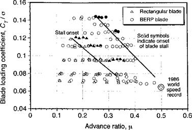
The performance of the BERP rotor is confirmed by the results shown in Fig. 6.23, which is based on actual flight tests using the Lynx helicopter – see Perry et al. (1998). The results are shown in terms of blade loading coefficient versus advance ratio. Clearly the BERP rotor demonstrates a significant increase in the operational flight envelope. Further results are shown by Perry et al. (1998), who compared the BERP rotor with other rotor blades in terms of hovering performance and the maximum thrust capability in forward flight. Despite some controversy about comparing rotor performance in forward flight on the basis of weighted solidities [see Amer (1989) and Perry (1989)] the performance gains of the BERP rotor are convincing and clearly demonstrate the benefits of a careful synthesis of both improved airfoil design and blade planform shape in the design of better helicopter rotors suitable

Case Study: The BERP Rotor

Figure 6.23 Flight envelope of the Lynx with standard rectangular blades and BERP

blades. Data source: Perry et al. (1998).

for high-speed forward flight. The latest derivatives of the BERP blade have used some anhedral over the tip region, which provides some additional gains in performance. The success of the BERP program has seen the blades retrofitted to the fleet of military’ Lynx helicopters, and the design is also used on the EH-101 helicopter.