Category The Aerodynamic Design of Aircraft

Interfering wings and ground effects

5.7 On classical and swept types of aircraft, various lifting surfaces may be placed in the flowfield of others and may thus interfere with one another. In most cases, the vortex wakes be­hind wings play an important part. We want to give a brief survey here of the main physical interference effects that must be borne in mind and understood in aircraft design, under the following main headings:

the structure of vortex wakes;

a small wing downstream of a large wing, e. g. the tailplane in the downwash field of the main wing;

a small wing upstream of a large wing, e. g. foreplanes; two similar wings close to one another, e. g. biplanes or tandem wings; a wing close to the ground, i. e. in the flowfield of its image in the ground; intersecting wings, e. g fins and tailplanes.

All these problems have some aspects in common, which could be exploited to develop a unified theoretical treatment. This will be discussed first.

In all cases, the flowfield of a thick lifting surface must be determined. If the velocity components induced by it at the location of the other lifting sur­face are known, then the properties of the latter can be calculated. If the interference is mutual, that is, if the properties of the wings involved must be expected to be strongly interdependent, then an iterative procedure can be

applied to obtain the final answer. Such a procedure should converge since we know, for physical reasons, that a solution exists and that it will usually be a relatively small perturbation of the solution for the lifting surface alone in an undisturbed stream. In any case, the interference should not change the type of flow over any part of a well-designed aircraft.

The means for carrying out such a procedure are already available for inviscid subcritical flows: С C L Sells (1969) has developed a practical method for computing the induced downwash field on and off the wing plane for wings with a given load distribution; and J A Ledger (1972) has developed a similar and compatible method for computing the velocity field of wings of given thickness. The framework of the RAE Standard Method can then be used to calculate loa­dings and pressure distributions in inviscid flow; an iterative design proce­dure, as developed for single wings by С C L Sells (1974), can in fact be car­ried out along the same lines as those described in Section 4.3. However, such a unified treatment has not yet been worked out. The older methods discussed below are, therefore, ready to be superseded, but they may be used, neverthe­less, to explain the physical phenomena.

Whichever way the problem is treated, there remains one fundamental difficul­ty whenever free vortex wakes are involved: the structure and position of such a vortex sheet are, in general, not known beforehand and it is difficult to determine them, theoretically or experimentally, when they need to be known. Therefore, we begin with a brief discussion of vortex wakes in the context of interfering wings, bearing in mind the properties of vortex sheets and their rolled-up cores already described in Sections 2.4 and again in 6.3.

On a well-designed classical or swept aircraft, vortex sheets spring from se­paration lines which are firmly fixed along aerodynamically sharp edges. Un­controlled separations lead to vortex formations, such as the body vortices discussed in Section 5.5 in connection with Figs. 5.32 to 5.36, which are ge­nerally undesirable and unpredictable. Therefore, we consider here only well – ordered flows with fixed separation lines, generally along the trailing edges.

Interfering wings and ground effects

RAE IOO t/c = 0-1 A = 6 c*=7° x/c = 4

Fig. 5.61 Total-head contours in a transverse plane behind a rectangular wing at low speeds. After Maskell (1972)

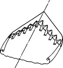
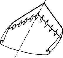
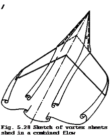
The structure of the vortex sheet trailing behind the main wing has already been discussed several times, especially the rolling-up along its free edges (see Section 4.6). A typical shape of the wake behind a simple unswept wing can be seen in Fig. 5.61, as measured by E C Maskell (1972). Lines along which the total head differs from that in the mainstream by a certain amount indica­te several features which are important in the present context: that the pre­sence of a viscous wake does not conceal or efface the existence of a layer of vorticity which may be regarded as a thin sheet lying within the contours indicated; that this sheet is nearly flat over much of the span and rolls up

near the edges into vortex cores; and that the sheet is displaced downwards relative to the wing by a significant amount. These measurements were made at a distance behind the wing which roughly corresponds to that of a tailpla – ne on an aircraft, i. e. about one semispan behind the wing. It is understan­dable, therefore, that further upstream and especially when considering the wing itself, a flow model with a plane vortex sheet along the mainstream direction should be adequate, except in the tip regions, as explained in Sec­tion 4.6. Further downstream, on the other hand, the rolling-up process will continue and eventually most of the vorticity will be concentrated in the two cores. As stated before, rolled-up vortex sheets are extraordinarily stable anti-dissipation devices, and so the two vortex cores behind a wing may per­sist in tightly rolled-up form up to a distance between 10^ and 10* times the wing span, as can readily be observed in the sky.

This persistence and stability of vortex cores is of practical importance sin­ce an aircraft flying into the swirling vortex wake of another aircraft ahead of it may be thrown out of control, especially if the leading aircraft is big­ger. This risk is so serious that separation distances between large aircraft of about 10 km are imposed for reasons of safety. This in turn implies long separation times, especially in airport operations and, in view of the severe economic and operational consequences, much work is being done to find out more about the structure of vortex cores and also to try to find means for dissipating them at shorter distances. Some of this work has already been mentioned in Section 4.6, and we refer here also to further work on the struc­ture and on the decay of trailing vortices by J N Nielsen & R G Schwind (1970), G M Williams (1972), D W Moore (1972), N A Chigier & V R Corsiglia (1972),

V R Corsiglia (1973), P G Saffman (1973), I Tombach (1973), V J Rossow (1973),

P F Jordan (1973), and Z El-Ramly et al. (1975). A simple and effective meth­od for estimating the rolling-up and the velocity distributions has been deve­loped by A J Bilanin & C duP Donaldson (1975). There are also some review pa­pers on the behaviour of vortex cores by P L Bisgood et al. (1970), R L Maltby & F W Dee (1971), G H Lee (1973) and (1975), C duP Donaldson & A J Bilanin

(1975) , as well as the proceedings of a conference on aircraft wakes (see J H Olsen et al. (1971)). P L Bisgood (1973) has reported especially on measure­ments made in flight.

Several mechanisms have been identified which may disrupt the cores: vortex breakdown (see e. g. M G Hall (1972); also Section 6.3); instabilities which oc­cur in vortex pairs, such as lateral waves and the formation of loops’, or the generation of lateral disturbances, such as pairs of counterrotating cores along the main cores (see e. g. J К Harvey (1971), H Bippes (1973), J P Narain & M S Uberoi (1973)). The formation of loops is probably the most powerful effect of these in bringing the vortex trail to an end. It was first observed in flight tests by R Rose & F W Dee (1963). The mutual interaction between the pair of trailing vortices begins a long way behind the generating aircraft with a sinusoidal distortion in the horizontal plane. Its amplitude increases with time until, eventually, the two trails appear to touch and join up to form elongated loops. These persist for a considerable time. Finally, the loops disperse and the trail disappears. E C Maskell (unpublished; see P L Bisgood et al. (1970)) has derived semi-empirical relations for the interac­tion time from a dimensional analysis of a simplified model of the flow, which describes the observations well. S Crow (1969) and (1970) has treated the cause of looping as an instability of the two cores (see also A Mager (1972)).

Attempts have been made to reduce the strength of the vortex cores or to pro­voke an earlier breakdown by special shaping of the wing tips.

This has been proposed by several people (see e. g. V J Rossow (1975)), and we refer here to the Sikorsky tip shape where the trailing edge is curved so. that the wing chord decreases rapidly to a small value at the tip (see J Rorke & R Moffitt (1973)). This may be effective on helicopter blades where a similar problem arises: to reduce the interference between the trailing vortex from one blade and the following blade. On the whole, none of these problems can be said to have been clarified satisfactorily.

The problem of the far wake matters especially when the aircraft approaches the ground. It can readily be seen that the vortex sheet with its rolled-up cores as in Fig. 5.61 cannot continue to descend without modification (see e. g. P L Bisgood et at. (1970) J N Hallcock (1972), С E Brown (1975)). When the cores get near the ground, their rate of descent is checked when the ef­fect of the image vortices in the ground is felt. Flight experiments by F W Dee & 0 P Nicholas (1968) have shown that the motion of the cores agrees mo­derately well with the paths predicted by a simple theory for a pair of con­centrated vortices above an infinite plane, that is, the cores follow curves, when projected on to the crossflow plane, of the form 1/y^ + 1/z^ = constant. But a closer experimental inspection of the flowfield induced by trailing vor­tices near the ground by J К Harvey & F J Perry (1971) has revealed that the crossflow over the ground leads to suction peaks underneath each core, follow­ed by "secondary" flow separations from the ground. These separation surfaces are also vortex sheets which roll up into cores, with vorticity in the opposi­te sense to that in the "primary" cores behind the aircraft. It appears that the secondary cores grow to a strength comparable with that in the primary co­res and induce these to rise again quite rapidly away from the ground, whereas the secondary cores are evidently prevented from spiralling around the free primary cores by their feeding vortex sheets which tie them to the ground.

As a very rough picture, we may visualise that the vortex cores from the air­craft stabilise at a height of about one half of the wing span above the ground. At the same time, the two cores begin to move apart. At the stabilised height, each core is moving laterally away from the aircraft with a speed about equal to the rate of descent of the aircraft, i. e. at between 2 and 3 m/sec. This speed is of the same order as possible crosswinds on the airfield. Crosswinds greater than that may blow the wake sideways away from the runway and make the imposed separation distances unnecessary. But until the fundamental fluid me­chanics of these vortex motions and the conditions in the atmosphere near the ground are clarified further, no steps to relax the regulations can be taken.

Подпись: MT Interfering wings and ground effects Подпись: (5.29)

Consider now the relatively simple flow past the taiVptane of an aircraft. The flow direction there is inclined downward by an amount v/Vg = otp which, to a first order, may be taken to be the doumwash that is self-induced by the bound and trailing vortex system of the main wing: in general, the tailplane is too small and too far away to affect the loading and hence the vortex system of the main wing in return. This downwash usually detracts from the purpose of the tailplane, which is to make a stabilising contribution to the pitching moment of the aircraft:

Here, S^, and are the plan area and moment arm of the tailplane and A<Xq is the difference between the no-lift angles of wing and tailplane, related to the tail setting, which might be changed during flight for trimming purposes;

and ry is an efficiency factor which differs from unity when the flow near the tailplane is significantly non-uniform (this will be discussed further in Section 5.8 below). When considering the longitudinal stability of an air­craft, we have to know also the change of the pitching moment with the angle of incidence, which is proportional to

Interfering wings and ground effects(5.30)

Interfering wings and ground effects Подпись: 2 0

Thus we are interested in the value of otjj in relation to a and also of the slope dojj/doi. If we know aD in terms of cu ■ С^/тгА, then these quan­tities can be worked out for a given wing.

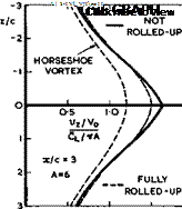
Fig. 5.62 Downwash behind rectangular wing

Interfering wings and ground effects

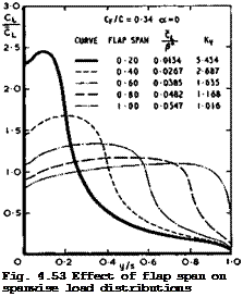
Fig. 5.62 shows some typical downwash distributions at and above and below the centreline one semispan behind a simple rectangular wing, as calculated by I FlUgge-Lotz & D KUchemann (1938). Several features should be noted: that there is a relatively small difference between the downwash values calculated for a fully-rolled-up vortex sheet and for one which is still flat and not rolled-up at all – experimental evidence so far has shown that the values for the not-rolled-кр vortex sheet are closer to reality, as would be expected from the results in Fig. 5.61; that the representation of the vortex wake by a single horseshoe vortex gives quite different values which are inadequate; that the downwash depends strongly on the vertical position of the tailplane relative to the vortex sheet. The latter implies that the downward motion of of the trailing vortex sheet must be taken into account when determining the position of the tailplane relative to the vortex sheet. A first approximation to the position of the vortex sheet can be obtained by integrating the values of vz(x) along x. A typical result of such an integration is shown in Fig. 5.63. The downward displacement of the vortex sheet is significant.

Downwash curves as in Fig. 5.62 also depend strongly on the actual spanwise loading over the main wing. For example, the peak of the downwash curve is much sharper than that shown in Fig. 5.62 for a wing with elliptic spanwise loading; it reaches values greater than 2Cl/ttA, i. e. it overshoots the value at infinity behind the wing as a result of the contribution from the bound vortices. The value of vz(x, y) is also sensitive to details of the actual spanwise loading, such as holes in the CL(y)-curve near the centre of sweptback wings. We can see from Fig. 4.22 how this may lead to the shedding of trailing vortices of the opposite sign which contribute an upwash component near the centreline. A similar effect, in reducing the downwash, may be achieved on any wing by even a small out-out in the wing planform which reduces the chord near the centreline or in the wing-fuselage junction.

For the same reason, the downwash at the tail is sensitive to other changes in the spanwise loading, such as those brought about by the deflection of part-span flaps. Quite often, the downwash may vary along the span of the tailplane so that the spanwise loading over the tailplane is affected.

With regard to flight stability and specifically in some manoeuvres, changes of the downwash with the angle of incidence matter (see (5.30)). The tail – plane may then move relative to the vortex wake of the main wing. If the tail is initially in a low position just below the sheet, then increase in the angle of incidence may move it away from the sheet, with a consequent re­duction in downwash (see Fig. 5.62). This is beneficial and increases the effectiveness of the tail. Alternatively, a high-tail position may have the opposite effect. Clearly, a position where the tail is likely to move through the vortex sheet should be avoided. This is not always possible when the aircraft is flown close to the limits of normal flight conditions, especially at high angles of attack near or, inadvertently, beyond the stall when a high tail may move into a Wide wake of separated flow behind the main wing, where the total head (and hence rvp ) is very low. As explained by H H В M Thomas

(1971) , such critical flight conditions are generally only encountered in the course of a manoeuvre. Handling difficulties may then on occasion lead to a complete loss of control. Thomas has also pointed out design features which can help to avoid these dangerous situations and which should enable the pilot to handle the aircraft safely.

Consider now what happens if a small wing, or foreplane, is put upstream of a larger wing, which is then influenced by the vortex wake shed by the small wing. Again, we assume, to a first order, that the loading over the small wing is not influenced by the presence of the large wing. But the loading over the large rear wing may then be strongly affected by the wake of the small wing: the rear wing is not just subjected to a nearly uniform downwash

but, if its size is large enough, it will pick up the whole upwash and down – wash field in the "Trefftz plane" of the forward wing. In the extreme case, the rear wing will straighten out the flow completely and thus experience an additional lift force which is equal and opposite to that of the wing in front. Hence, the overall lift of the combination of the two wings is not changed.

But a pitching moment is generated and such a foreplane may, therefore, be regarded principally as a trimming device (see e. g. S В Gates (1939)). In reality, matters depend very much on the actual sizes of the wings and on their relative positions, and detailed calculations are needed to determine the actual forces and moments. Such calculations have been carried out for par­ticular combinations of two wings in a supersonic flow by M С P Firmin &

W J Bartlett (1960) and compared with the results of experiments. They demonstrated that the flowfield of the foreplane induces overpressures and suction peaks on either side of the spanwise station of the (in this case fully – rolled-up) vortex core, and that these peaks are situated along Mach lines and are attenuated with distance downstream. They found that it is necessary to take account also of the induced crossflow in determining the pressure distribution. Similar calculations, allowing also for the presence of a body and making the assumption that the whole configuration may be regarded as aerodynamically slender, have been done by P R Owen & E C Maskell (1951). It turned out in all the cases considered that the actual amount of lift taken up by the rear wing and the actual pitching moment obtained is a matter of fine detail and hence rather uncertain. Detailed investigations for flows at subsonic speeds have not yet been carried out, but the general effects must be expected to be of a similar nature.

The greatest uncertainty and the weakness of the available methods for estima­ting the properties of such flows stem from the fact that the relative ‘position of the free vortex sheet and its structure are not known in advance. The degree of rolling-up and the distance of the vortex sheet from the affected wing obviously determine the results to a large extent. In addition, the actual shape of the sheet may be distorted by interference from neighbouring surfaces. During manoeuvres, the vortex cores may assume asymmetric posit­ions with regard to the rear wing, and possibly to a fin, and thus induce also side forces as well as rolling and yawing moments. All these effects may be time-dependent and in their complexity very difficult to determine, either theoretically or experimentally. Foreplanes with free trailing vortex sheets can, therefore, not in general be regarded as suitable design elements for aircraft.

We may mention in this context an interesting phenomenon which has been ob­served by J D Bird (1952) in the wake of cruciform wings in the shape of an X set at an angle of incidence. The two pairs of fully-rolled-up cores far downstream interact in a manner similar to that of two vortex rings, as des­cribed by H von Helmholtz (1868). Whereas the lower pair draws apart, the upper pair moves towards one another and downwards; eventually, they pass through in between the lower pair and the whole process, which has been called leap-frogging, is repeated. Note that this motion differs from that of a vortex pair near the ground, described above; there, the rotation about the lower (image) pair is in the opposite sense to that of the pair above the ground; this keeps them apart.

Consider now the interference between two wings which are approximately of the same size and relatively close to one another, i. e. of the order of one wing chord apart horizontally or vertically. The interference is then mutual and the simplifying assumptions made above are no longer appropriate. Although such configurations as tandem wings (see e. g. В Laschka et al. (1969),

R Dat & Y Akamatsu (1971), J Becker (1974)) and biplanes (see e. g. D Kuchemann (1938)) are rarely found in practice nowadays, we mention here some physical features of such interfering flows, which are of general interest and may be useful in other applications.

In the biplane theory у an iterative procedure was applied, whereby the properties of the two wings in isolation were calculated first, using the classical aerofoil equation (4.56) or (4.81). These solutions were then used to determine the velocity components induced by one wing at the position of the other and subsequently the properties of each wing in these induced flows could be worked out. This procedure could be repeated. It was found to con­verge rapidly: sometimes, one step or, at the most three steps were sufficient in the case of biplanes. Unlike many modern computer procedures, where the

. 2 3

number of iterations may be of the order of 10 or 10 , such an iteration is based on known physical properties and hence can be expected to converge much more rapidly.

Подпись: r Interfering wings and ground effects Подпись: (5.31)

In the biplane theory again, some simplifications were successfully applied to take into account that one wing induces at the other a flow with an increa­sed or reduced velocity V = Vq + Av, and that the flow is also curved with a radius of curvature in planes у = constant:

Подпись: Да Подпись: (5.32)
Interfering wings and ground effects

Within classical aerofoil theory, by (4.48) and (4.56), the velocity change may be interpreted as a change in the geometric angle of incidence:

Interfering wings and ground effects Подпись: (5.33)

and the curvature of the flow as another:

according to H Glauert (1926) and E Pistolesi (1936). The last relation im­plies that a plane aerofoil in a curved stream has the same lift as a suitab­ly cambered aerofoil with the opposite curvature in a parallel stream. Both relations apply only in irrotational flows when the perturbations can be taken to be small and when non-uniformities in the field, i. e. changes of Дv and of r in the directions of either of the three coordinates, can be assumed to be insignificant. What happens when such non-uniformities matter and are as­sociated with vorticity in the stream will’ be discussed in Section 5.8. For biplanes and similar configurations, the approximations (5.32) and (5.33) were shown to be adequate and allowed a theory to be developed entirely within the framework of classical aerofoil theory, described in Section 4.3. Biplanes also turned out to be one of the few cases where it is usually permissible to assume that one wing is in the farfield of the other so that, for the purpose of calculating the interference effects, the bound vortices can be replaced by a single "lifting line" (in the sense described in connection with Fig.3.3). But there are also exceptions (see D KUchemann (1938)), where the assumption of a lifting line leads to significant errors: this concept, however attrac­tive it may seem, should always be handled with extreme caution.

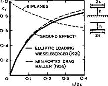
Biplanes also represent an instructive example of a non-planar wing system which may have a lower vortex drag than a single wing of the same span and overall lift. The lowest vortex drag can be determined from considerations of the flow in the Trefftz plane, as explained in Section 3.2. This problem was solved by M M Munk and L Prandtl and the solutions may be found in L Prandtl & A Betz (1927). The result may be expressed in terms of the vortex drag fac­tor, defined by (3.38), and a typical example is shown in Fig. 5.64. The overall vortex drag of a biplane is always smaller than that of the monoplane which carries the same overall lift and which has the same span as the larger of the biplane wings, and the value of Ky may fall considerably below unity as the wings move further apart. Alternatively, a monoplane must have an as­pect ratio which is 1/ -/Ky times that of the biplane to carry the same lift as the biplane for the same vortex drag. On the other hand, a biplane has usually a larger surface area and hence a greater skin-friction drag than the
corresponding monoplane. Also, it has been found that mechanical high-lift devices are less effective on biplanes than on monoplanes. Thus the aerodyna-
Interfering wings and ground effectsLIVE GRAPH

Click here to view

Fig, 5.64 The vortex drag factors of biplanes and of a wing near the ground mic advantages of biplanes were largely offset and what remained was the pos­sibility of designing a light structure for two wings joined by struts. Even this advantage was eroded and the biplane was considered doomed when structu­ral engineers learnt how to design lightweight structures for cantilever mo­noplane wings (the first being H Junkers in 1915).

Finally, we mention an interesting interference effect between two wings in a supersonic stream: a non-tifting biplane can be designed to have no wavedrag due to volume, i. e. Kq » 0 in (3.44). As pointed out by A Busemann (1935), the two outer surfaces can lie along the mainstream and the two inner surfaces facing each other may be curved as compression and expansion surfaces in such a way that the two weak wave systems cancel each other completely so that the air emerges again from between the trailing edges as a parallel stream and no disturbances are left behind.

We turn now to the flow past a wing near the ground, which may be regarded as an interference between the wing and its image in the ground. (This problem is closely related to that of a wing within the constraints of the solid walls of a windtunnel. This will not be discussed here. See e. g. H C Garner et at,

(1966) ). The two wings are now of exactly the same size but, in contrast to biplanes, the circulation about one is equal and opposite to that about the other. This has remarkable consequences. Consider first the vortex drag when a wing approaches the ground. This problem has been treated in the classical way by P de Haller (1936) who calculated the minimum vortex drag for a wing of given span and lift. Earlier, C Wieselsberger (1921) had calculated the vor­tex drag on the assumption that the spanwise loadings were elliptic. Results from both calculations are shown in Fig.5.64. They do not differ much, but the ground effect has the opposite trend with distance h from the interfe­rence effect found for biplanes: it increases as the ground is approached. (Note that the definitions of h do not strictly correspond in the two cases: the ground effect would appear to be relatively even stronger if the same de­finition had been used). This reduction of the vortex drag implies a reduc­tion of the induced angle of incidence and hence an increase of the effective angle of incidence at the wing, for a given geometric angle. It follows that the ground effect produces an increase in the overall lift slope of threedi­mensional wings, as the distance becomes smaller.

Such a powerful effect must be accompanied by strong repercussions on the oth­er forces and moments and on the detailed pressure distribution over the wing, especially on swept wings where different parts will be at different distan­ces from the ground. The effectiveness of high-lift devices, in particular, will be affected during take-off and during the landing flare. In view of this, it seems strange that not much work has yet been done to determine the properties of threedimensional swept wings. However, an extension of the RAE Standard Method, as described above, has now been provided by С C L Sells

(1976) , which allows an iterative calculation of the flow past a thick cambe­red wing near the ground, and which is accurate as well as practical. There is also a theory by В Laschka et at, (1967) and specific solutions have been obtained by S E Widnall & T M Barrows (1970) and extended by T Kida & Y Miyai

(1973) . D Hummel (1973) has developed a non-linear theory for threedimensio­nal wings and found good agreement with measurements. As in so many other instances, most existing theories are concerned with twodimensional aerofoils, and we use these results to describe some of the physical effects caused by the proximity of the ground.

The example of a twodimensional flat plate near the ground shows how the sec­tional lift coefficient CL is affected, by comparison with the lift C-r0 in free air. The results in Fig. 5.65 are exact and have been obtained by S To – motika et er7.(1933), using the method of conformal transformations. This is
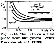
Подпись: Fig. 5.65 The lift on a flat plate near the ground. After Tomotika et al> (1933) LIVE GRAPH

Click here to view rather cumbersome, as it involves doubly-connected regions. A much simpler approximate theory by I Tani et at, (1937), using the classical Bimbaum loa­ding distributions, gives quite accurate results and significant errors appear only when h/c < 1/4. A summary of these kinds of investigations has been gi­ven by Y Hamal (1953). All these results show that the lift depends not only on the distance h/c from the ground but also on the angle of incidence: in some conditions, the lift is less than the free-air value, in others it is higher. What actually happens on a threedimensional wing must, therefore, be a rather complex interaction, especially during the landing flare, when the actual angle of incidence may change rapidly with time so that dynamic effects may matter. Therefore, we cannot yet fully explain why some particular air­craft will "land itself", presumably by generating the right amount of extra lift in the right place so as to provide the necessary deceleration and nose- down pitching moment, and why other aircraft do not. To design aircraft from the outset which have the desired safe behaviour during this manoeuvre is as yet beyond our means.

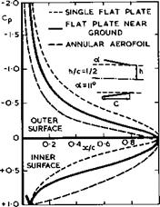
An explanation of the sectional lift changes near the ground has been given by J A Bagley (1959) by calculating the pressure distribution over a twodimensio­nal flat plate. An example is shown in Fig. 5.66. Similar results have been obtained by V Losito (1972). We find that the effect of the ground on the

LIVE GRAPH

Click here to view flow is such that the lift is reduced over the upper surface and increased over the lower surface so that the overall lift depends on how this balance works out. Evidently, as the wing approaches the ground, the mass flow that

Interfering wings and ground effects

Fig. 5.66 Calculated pressure distributions for a twodimensional flat plate near the ground and for an annular aerofoil. After Bagley (1959)


passes through between wing and ground is reduced and hence the pressure in­creased, and so there is eventually an overall gain in lift on a twodimensio­nal aerofoil section. The sectional lift slope is, therefore, a highly non­linear function of h/c and a. We digress here to point out that this flow is closely related to that past annular aerofoils (see e. g. D KUchemann (1941), D KUchemann & J Weber (1943), J Weissinger (1956), J A Bagley et al. (1958)).

As can be seen from the example in Fig. 5.66, the effects are similar but even more pronounced on annular aerofoils because of the threedimensional nature of the flow.

It is tempting to try to estimate the ground effect by representing the wing not by a continuous distribution of vorticity, as in Bagleyfs theory, but by a single "lifting line". That this leads, once again, to completely mislea­ding conclusions has been shown by E C Maskell (1960, unpublished) who, at the same time, clarified the important effect that the ground has on the pressure distribution due to thickness. He considered the instructive case of invis­cid, incompressible, flow past a circular cylinder in the presence of the ground and showed that a pair of circular cylinders, without circulation about either, can be represented exactly by two sets of doublets in a uniform stream, of strengths у, situated at a radial distance r from the centre of each unit circle, with their axes normal to the radius vector r, together with their reflections in the circle, of strengths y/r2 , situated at the inverse point at radial distances 1/r from the centre of the circle. Each set has, as its principal member, a doublet of strength у – 2ttV0 at the centre of a

Подпись:Подпись: rSucceeding members diminish in strength in the se-

Подпись:2ttV,

(5.34)

Г – —,

Подпись: 1 Подпись: (5.35)
Interfering wings and ground effects

and are displaced from the centre of one cylinder in the direction of the other in the sequence

Подпись: Гр(r “ rr) Подпись: (5.36)
Interfering wings and ground effects

Each cylinder can be given a circulation Г around it, if line vortices are so placed as to be at the inverse point of either circle, that is to say, they must be placed at the radial distance Гр from the centre of each circle in the direction towards the ground, such that

The resulting tangential velocities around the cylinder induced by the doubl­ets and vortices can then be calculated. By applying a form of Kutta condi­tion, the circulation Г can be chosen to make the overall tangential veloci­ty zero at a certain circumferential angle a, as indicated in Fig. 5.67.
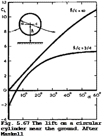
Подпись: Fig. 5.67 The lift on a circular cylinder near the ground. After Maskell LIVE GRAPH

Click here to view

The lift is determined by integrating the pressures, and typical results are shown in Fig. 5.67. When the attachment and separation points are located op­posite to each other (i. e. when a = 0 in Fig. 5.67), then the cylinder is at­tracted towards the ground. There is then one condition, with circulation, when the cylinder experiences no force. For greater circulations, there is a lift force on the cylinder. It will be seen that the lift is a highly non­linear function of a and that the ground effect is so strong that CL rea­ches a maximum value even in inviscid flow: thickness effects combined with circulation may be so powerful that the flow of air between the body and the ground is completely stopped.

J A Bagley (1959) has shown how these effects manifest themselves on а Ыггек
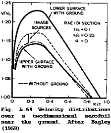
lifting aerofoil in a twodimensional inviscid flow. Even a thick aerofoil at zero angle of incidence causes an asymmetric flow with circulation near the ground, as can be seen from the example in Fig. 5.68. Source and vortex dis­tributions along the chord are needed to represent the aerofoil. Unlike the
Подпись: Fig. 5.68 Velocity distributions over a twodimensional aerofoil near the ground. After Bagley (1959) LIVE GRAPH

Click here to view flow past a flat plate in Fig. 5.66, the flow due to thickness generates the higher velocities on the lower surface and the lift is negative, i. e. direc­ted towards the ground. Bagley*s method can deal with general section shapes and the results have been found to compare well with experimental results. The method is of a kind that can readily be incorporated into the framework of the RAE Standard Method. It has not yet been extended to threedimensional wings.

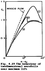
In view of the rather drastic changes in the pressure distribution which the ground effects cause, we must expect that the stalling of wings may also be affected. In particular, it is possible that the type of stall may switch over from one to another (see Section 4.7, Fig. 4.39), especially if the wing is close to the borderline between two types. This interaction is so complex that values of С^шх cannot yet be predicted with confidence in given cases. In general, the ground effect is unfavourable on sweptback wings of high as­pect ratio with powerful high-lift devices. In view of this, the information needed will often have to be supplied by experiments. But such tests have their own problems. If a special board is provided to represent the ground, a circulation will, in general, be generated around it, that distorts the flow to which the model is exposed. To prevent this, J A Bagley (1959) added a sharp leading edge to the ground board, with pressure tappings above and below it. A flap at the trailing edge of the ground board was then deflected until the pressure readings were the same, indicating that at least the attachment streamsurface would lie along the leading edge of the board. Even then, a boundary layer will develop along the ground board in what might be a strong adverse pressure gradient (see e. g. Fig. 5.66). As long as the boundary lay­er does not separate, its displacement thickness may be calculated from the measured pressure distribution over the ground, say, as proposed by L F East (1970), and the actual distance between model and ground corrected according­ly. Another step further would be to apply boundary-layer suction over the ground board. Separation might thereby be prevented, in principle, but the

problem is then to adjust the suction rates everywhere in such a way that the associated sink effect does not distort the flow. Yet another step further is to move the ground surface along in its plane at a speed which simulates in the windtunnel the correct relative speed between the aircraft in flight and the ground. This can be done by means of a moving belt, which is mechanically complicated but has been accomplished successfully, e. g. by S F J Butler et al.

(1963) , J Williams & S F J Butler (1964), and T R Turner (1967). The latter has provided a rough criterion for conditions when a moving ground is needed, namely, when the value of the parameter C^/(h/2s) exceeds about 20. An ex­cellent review of these and other testing techniques has been given by Ph Poisson-Quinton (1968).

We turn now to the flows near the junctions of intersecting wings. That such intersections might cause strong disturbances and high "parasite drag" forces was recognised early on when wings were supported by struts which might cross each other (see e. g. M Kohler (1938)). Now we find such intersections mainly between fin and tailplane.

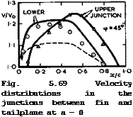
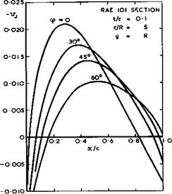
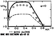
Consider first what happens when two identical wings without lift and without sweep intersect at right angles to each other. To a first order, we may ex­pect that the two flowfields can be superimposed so that the velocity incre­ment along the junction should be twice that of the wing alone. However, thin­king of each wing as being represented by a distribution of sources, we recog­nise that this simple addition implies that the volume which the two wings have in common is represented twice. A source distribution corresponding to this volume should, therefore, be subtracted*) and the velocity increment along the junction will then be somewhat less than twice the individual con­tributions. This is borne out by experiments, as shown by the example in the upper part of Fig. 5.69 (from tests by D Kiichemann & J Weber (1948)). The full line corresponds to the simple addition, and the measured velocity level is below that by an amount which is roughly the same as that induced by a sour­ce distribution representing the common volume (which may readily be calcula­ted) . The experiments also showed that the interference effect fades out with distance away from the junction like the flowfield of the interfering wing. Roughly, the velocity increment reaches that of a single wing at a distance Ду = c/2.

Consider now what happens when one or both wings are swept, as in most practi­cal cases. In accordance with the concepts developed for wing-fuselage inter­ference, we must expect that the main effect will be that one wing acts as a reflection plane to the other. Thus kink effects will come in, in addition to the superposition of sheared^wing velocity increments, as in (4.86) for single non-lifting wings. These kink effects may again be regarded as additive, to a first order. For example, consider two intersecting wings: a sweptback tail – plane and a sweptback fin at zero lift, sweep angles, section shapes, and wing chords being the same. Along the lower junction, the fin behaves as though it has a sweptforward kink, owing to its reflection in the tailplane; whereas the tailplane by its reflection in the fin behaves as though it has a sweptback kink. Thus the two kink effects should cancel one another, leaving only two sheared-wing terms to be added (minus the source term from the com­mon volume, as before). Along the upper junction, both fin and tailplane should exhibit sweptback kink effects, which should thus be added together.

■’This is, of course, basically the same concept as that of the "source method" for estimating wing-fuselage interference, as discussed in Section 5.6 .

Again, this simple argument is borne out by experiments, as shown by an example in the lower part of Fig. 5.69 (from tests by D KUchemann (1948)). The full lines have been calculated in the way just described and evidently represent the overall trends quite well.
Подпись: RAE ЮЗ SECTION t/c=O I2 LIVE GRAPH

Подпись: Fig. 5.69 Velocity distributions in the junctions between fin and tailplane at a - 0

Click here to view

These principles – superposition and reflection – may be applied quite gen­erally. Lifting wings can also be treated in this way. The same principles may also be applied to other more complex configurations, such as struts or stores attached to wings. In all such junctions, flowfields may be superposed and kink effects will appear if any of the members are swept. But the results cannot be expected to be very accurate, especially near the leading and trail­ing edges where such a simple theory cannot represent details. Panel methods cannot be expected to be very accurate either, unless the reflection behav­iour is properly incorporated, as explained in connection with Fig. 5.43. Also, there will be strong but as yet largely unknown viscous effects in the junc­tions. Thus, for the time being, only the main overall features of the flow past intersecting wings can be determined.

These large interference effects between intersecting wings pose a severe design problem. The high local velocities and the possible loss of effective sweep lead to low critical Mach numbers which, in general, cannot be tolera­ted. For swept fin-tail combinations, the design can be made somewhat easier from the outset if fin and tail are separated by a fuselage, or if a swept – back tail is put on top of a sweptback fin. As explained above, the two kink effects then roughly cancel each other, at least along the lower junction.

Such cancellations occur quite generally when one wing, if folded around the intersection line into the plane of the other wing, forms a continuation of it. Even so, a difficult design problem remains if the aim is to derive the full benefit from sweep, i. e. if the isobars on all surfaces should at least be fully swept everywhere, following the design principle illustrated in Fig. 5.1 (b). One way of achieving this is to add a separate body between the intersecting surfaces and to shape the new junctions suitably. Such threedimensional bodies must be expected to have deep indentations to bring

Next Page

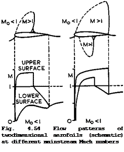
about the required large reductions and changes in the (basically two­dimensional) velocities in the manner of the sketch in Fig. 5.54. Thus these bodies will have to be fairly wide to begin with, where they intersect the leading edges of the wings. This implies, in turn, that the fairing must have a correspondingly long forebody so that its own self-induced velocities are not too high. Such a design may, therefore, end up with a rather large body and consequently a significant additional skin-friction drag. But the volume provided by the fairing may often serve some other useful purpose.

Interfering wings and ground effectsInterfering wings and ground effects

Fig. 5.70 Shape of a fairing in the junction between a sweptback fin and a sweptback tailplane. RAE 103 sections; t/c = 0.12 ; <p = 45°

A typical shape of such a fairing between intersecting fin and tail surfaces is shown in Fig. 5.70 (from a design by D Kuchemann (1948)). This fairing has local bulges in front of the leading edges so that its thickness there is four times the wing thickness. The junction shapes were designed to compensate for the various interference velocity increments, discussed above, using a quasi-cyliiider theory described in Section 5.6 and making small em­pirical adjustments. Inspite of the obvious shortcomings of such a theory, the fairing shown in Fig. 5.70 did produce fully-swept isobars on all the fin and tail surfaces at zero lift and also at a moderate lift on the tail – plane, at low speeds. The different shapes needed in the different junctions demonstrate clearly the nature of the different interference effects. A reliable theory for designing general fairing shapes of this kind has not yet been developed.

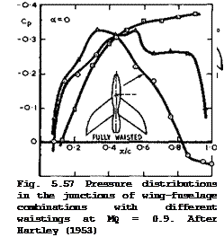
Actual fairings between fin and tailplane are often designed as a compromise allowing, for example, for flat surfaces required to prevent gaps on an all­moving tail. We note in this context that even partial fairings as opposed to complete fairings of the kind illustrated in Fig. 5.70, may bring some benefit. D E Hartley (1953) has shown, for example, that a rear fairing alone, much like the rear part of the fairing in Fig. 5.70, may effectively postpone the occurrence of severe buffeting to higher Mach numbers by breaking up strong oscillating shockwaves near the trailing edges of fin and tail, in a manner similar to that of rear bodies sketched in Fig. 5.27. The first successful application of such a rear fairing was to the tail of the Hunter aircraft by Sir Sidney Camm (see e. g. A P Cox & D A Kirby (1952)).

The interference phenomena discussed so far are undesirable nearfield side

Previous Page

effects of the main purpose of the fin-tail assembly; to produce required lift and side forces. These depend very strongly on the actual configura­tion. Although, on present knowledge, an adequate theory for designing fin – tail combinations to give the required, loadings could be developed, such a design theory does not yet exist. We are concerned here always with non­planar lifting systems, in an upwash or in a sidewind, and it is, therefore, not surprising that the Trefftz plane concepts have often been applied to calculate the properties of systems which give minimum vortex drag, when the induced downwash in the Trefftz plane is assumed to be constant along the span. Such non-planar combinations have been investigated by К Mangier (1938), V M Falkner & C Darwin (1945) and D Kuchemann & D J Kettle (1951) for wings with endplates. In the present case, such endplates can serve a useful func­tion as fins, which an equally effective extension of the span could not (see Section 3.2). J C Rotta (1942) has calculated the properties of wings with single plates; J Weber (1952) and (1954) those of wings with fences, of fin – fuselage, and of wing-nacelle arrangements; and J Weber & A C Hawk (1954) those of fin-tail-fuselage combinations. We mention here also the work of D E Hartley (1952) on wings with tip tanks, which deals with a similar problem.

Interfering wings and ground effects

Cyc/0t

Cyo/0=19 Cy/Cy0=l-9

Cy/Cy0=22

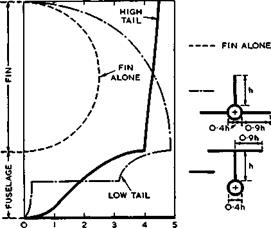
Fig. 5.71 Distributions of the side force on fin-fuselage-tail combinations in sideslip

Typical results of such calculations are shown in Fig. 5.71. We find that fin-tail-fuselage combinations are much more effective in generating a side- force than the fin alone would be; A low-tail configuration produces 1.9 times the side force of the fin alone, and a high-tail configuration 2.2 times that of the fin alone. In this respect, the interference between fin and tailplane is very beneficial.

Wing-fuselage interference

5.6 There is an extensive literature on the aerodynamic interference between wings and fuselages, and much material has been collected together in outstanding summary reports and surveys by HR Lawrence & A H Flax (1954), H Ashley & M T Landahl (1965), T E Labrujere &

H A Sytsma (1972), H Ashley & W P Rodden (1972), and R C Lock (1973). See al­so the papers published in AGARD CP-71 (1970) and the bibliography by P A New­man & D 0 Allison (1971), Recent years have seen the development of numerical methods which can deal with inviscid incompressible flows past wing-fuselage combinations. In general, these use in various ways distributions of singu­larities on discrete panels, replacing the continuous surface of the combina­tion, and we refer to the methods by J L Hess & A M 0 Smith (1967), F A Wood­ward (1968), W Kraus & P Sacher (1970), T E Labrujere, W Loeve & J W Sloof

(1970) , В Maskew (1970), H Komer (1969), (1972), and (1975), and A Roberts &

К Rundle (1972) and (1973). Here, we want to concentrate our attention on those flow phenomena which must be known and understood when it comes to the design of an aerodynamically well-behaved wing-fuselage combination. The ap­proximate theories discussed below, which allow some physical interpretation, serve this purpose best.

Interference effects are always largest in the function between intersecting bodies, and any worthwhile theory must get the behaviour in the junction right and properly represented. Therefore, we discuss first the flow along the junction between a wing and a fuselage which is assumed to be cylindrical and infinitely long. There are four main effects, all equally important in practice:

1 Displacement effects, arising from the thickness of the wing and the cur­ved intersection lines.

2 Lift effects^ arising from the circulatory flows around wing and fuselage.

3 Effects of asyrrmetry3 associated with the shape of the cross-section of the fuselage or with the position of the wing on the fuselage (mid, high, or low position).

4 Effects of viscosity over and above those present on the bodies in isola­tion, arising from the viscous flows along the corner formed by two walls.

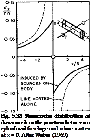
We consider first the lift effects so as to dispose of the far-too-simple no­tion of aerodynamic interference described at the beginning of Section 5.5, based on exact solutions obtained by J Lennertz (1927) and F Vandrey (1937). Consider again the flow past an infinite circular cylinder whose axis is par­allel to the mainstream, with an infinite line vortex normal to the mainstream, which passes through the axis of the cylinder and induces velocity components normal to the surface of the cylinder. This configuration is sketched in Fig. 5.38. One method to compensate for these interference velocities and to make

Подпись: Fig. 5.38 Streamwise distribution of downwash in the junction between a cylindrical fuselage and a line vortex at x = 0. After Weber (1969) LIVE GRAPH

Click here to view

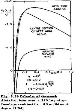
the cylinder into a streamsurface again is to place a suitable continuous dis­tribution of sources on the surface of the fuselage. This method has been de­veloped in detail and made into a practical routine procedure to deal with the general interference problem, which can readily be incorporated into the RAE Standard Method, by J Weber (1969), and J Weber & M G Joyce (1971), and (1974). The wing is then subjected to the velocity field of the source distribution on the fuselage. No downwash is induced at the line vortex, which is the basis of the mistaken "no-overall-interference" statement made above. The mistake can readily be discovered by calculating the complete downwash distribution along the junction with a wing of non-zero chord. As can be seen from the results in Fig. 5.38, the downwash is not zero as the line vortex is approached from either side, even though it is zero at the line itself. As a consequence, a complete theory, where the wing is represented by a chordwise distribution of bound vortices, leads to a continuous non-zero downwash dis­tribution in the junction. This means, in turn, that either the chordwise and spanwise load distribution on a given wing are changed by the fuselage inter­ference, or that the wing must be cambered and twisted if the initial loading

on the isolated wing is to be maintained everywhere (see D KUchemann (1967)). This interference effect is large, as can be seen from the example in Fig. 5.39, where the wing is assumed to be a thin flat plate far away from the

Wing-fuselage interference

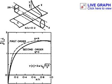
Fig. 5.39 Streamwise distribution of the downwash in the junction between a cylindrical fuselage and a (flat-plate) vortex distribution. After Weber (1969)

junction. The downwash induced in the junction is then far from constant. If the wing is to remain a flat plate right into the junction, the chordwise and spanwise loading will have to be calculated in this downwash field. These will differ significantly from the twodimensional flat-plate loading. An ite­rative procedure will have to be carried out because the source distribution over the fuselage, to cancel the normal velocity component there, will have to be adjusted to the velocity field of the changed loading over the wing. Al­ternatively, if the wing is to retain its twodimensional flat-plate loading all along the span, it will have to be cambered and twisted according to the va­riation of the downwash along the chord. Note that these effects already a­rise when the fuselage shape itself is so simple that it does not disturb the mainstream. Much more complex interference effects must be expected to occur on real fuselages. We note also that, once again, the concept of a "lifting line" is not only insufficient and unnecessary but also misleading and that it can cause serious errors when applied to the nearfieId.

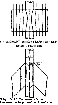
Consider now displacement effects, again first for an infinitely-long cylin­drical fuselage which, by itself, does not disturb the flow. In the general case, where the wing thickness t in the junction is not small as compared with the diameter 2R = d of the fuselage, the intersection lines will be curved significantly, as sketched in Fig. 5.40 (1). This will be associated with an interference velocity increment Vj in the junction, provided the flow follows the curved intersection lines, which usually applies if the inter­sections are not too shallow, that is, if the body diameter is more than, say,

twice the wing thickness.

Подпись: Fig. 5.40 Intersections between wings and a fuselage

(2) SWEPT WING : CONTINUATION
OF WING INSIDE FUSELAGE

This displacement effect manifested itself in a different form in calculations where a source distribution, representing a fuselage, was superimposed on a source distribution, representing an unswept wing. The resulting shape of the combination was determined by exact streamline tracing, by J Liese & F Vandrey (1942). This shape exhibited a pronounced bulge outside the original fuselage in the region of the junction where the fuselage now merged into the wing.

In the absence of fuselage sources, the fuselage itself would be formed of streamlines of the wing flow. This kind of fuselage shaping has been advoca­ted as a general design principle for unswept wings by H Muttray (1934) and also for swept subcritical wings by D Kuchemann (1947), W F Hilton (1955), and again by C L Bore (1971), on the grounds that this would produce a clean flow in the junction without adverse interference effects. Such streamline shaping can readily be applied when d » t, and has been found effective. The meth­od is not unique in the general case because a particular bunch of initial streamlines far upstream of the wing may be chosen arbitrarily, representing different cross sections (and nose shapes). This freedom of choice may be an advantage in practical cases. Like other design methods, this one applies only at one particular design condition.

The bulge referred to above is obviously caused by a local "surplus of sources" within the body in sections x = constant. If the original fuselage shape is to be maintained, e. g. if it is to remain a cylinder, then the wing sources
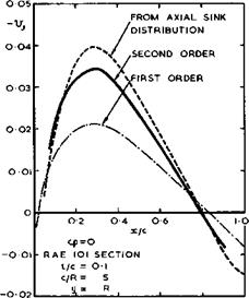
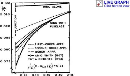
inside the fuselage should be taken out. The simplest way of doing this is to put a sink distribution along the axis of the fuselage, the strength of which is equal and opposite to the total of the wing sources inside the fuselage in section x – constant. This very crude kind of area treatment is surprising­ly accurate (see D KUchemann (1947), D KUchemann & J Weber (1953)). This can be seen from the example in Fig. 5.41 of an unswept wing on a cylindrical fuselage with d/t = 4. The streamwise velocity increment Vj is shown, as calculated by the area method and also by Weber’s theory referred to above.

For the latter, both first-order and second-order approximations are given. In the first-order approximation, the velocity field is computed, and the boun­dary conditions are fulfilled, on the chordal plane of the wing, as in linear­ised wing theory; in the second-order approximation, this is done on the sur­face of the wing. It is evidently important to include second-order terms in

Wing-fuselage interference

Fig. 5.41 Interference velocity in a wing-fuselage junction at zero lift

Подпись: determining Vj in the junction.
Подпись: LIVE GRAPH Click here to view

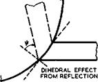
Consider now the junction effects when the wing is swept. A new feature is then that the wing section at the intersection tends to behave like the centre section of a swept wing (see D KUchemann (1947), D KUchemann & J Weber (1953)). This arises from the reflection of the wing in the surface of the fuselage, as can readily be seen in the limiting case d/t •+ « , i. e. when the wing is re­flected in a plane wall (see also J W Craggs & К W Mangier (1971)). Such a reflection effect remains also in the case of a curved wall and it is, there­fore, important to represent this local behaviour correctly in any theory.

This can readily be done in Weber’s theory by considering a kinked wing plan – form, as sketched in Fig. 5.40 (2). Note that the wing inside the fuselage is not the true reflection of the complete wing in the wall of the fuselage – this would be a much more complex curved shape. The aim in Weber’s method is to represent only the local reflection effect in the junction itself; for this, the shape considered is sufficient.

The velocity increments in the junction then consist not only of the term Vj, arising from the source distribution over the fuselage needed to make this in­to a streamsurface, but include two further terms arising from the wing flow:

Vg, the velocity increment over the corresponding sheared wing of infinite span; and v^ , the velocity increment due to the centre effect caused by the reflection. For the displacement flow considered here, vs and v^ are the two terms in (4.86), to a first order, or in (4.88). It is easy to see how the interference terms may be generalised and incorporated into a general re­lation.

Подпись:Sweep does not only introduce the centre effect in the junction but also af­fects the value of vj(x). The changes in Vj due to sweep may be quite lar­ge, as can be seen from the example in Fig. 5.42. These curves have been cal­culated by Weber’s first-order theory, the curve for zero sweep being the same as that in Fig. 5.41. If Vj is calculated by the approximate area method of putting compensating sinks along the axis of the fuselage, the strength of the sink distribution should have an overall factor cos <p, as proposed by D A Treadgold (1970, unpublished).

Wing-fuselage interference

Fig. 5.42 Interference velocity in wing-fuselage junctions according to first-order theory at zero lift

For fuselages of finite length, the source distribution along the axis or the surface distribution of sources may be continued to represent the front part as well as the rear part. When the fuselage shape has a cylindrical middle part and a distinct forebody and a distinct afterbody, as in many practical cases, it is convenient to think of the velocity along the junction as being composed of the following elements:

Vx> “ v0 + vx = V0 + VB + VJ + VS + Vc ’ (5-26)

where Vj is then restricted to the velocity increment due to interference with a cylindrical fuselage, and where Vg represents the contributions from the forebody and the afterbody. Every one of these terms has its own physical interpretation and meaning and, as will be seen below, one may be played a­gainst another to achieve certain design aims. For instance, junctions may be shaped so that Vj cancels v^ . One does not learn much if the four diffe­rent terms are all lumped together in one numerical answer.

Using any of these methods of representing wing and fuselage by singularities, we may calculate the complete inviscid, incompressible velocity field, in prin­ciple to any desired accuracy. In practice, the computational effort needed sets some limits. Weber’s method has been developed to a first-order and to a second-order accuracy and also to some alternative approximation which is especially convenient for practical purposes. These three approximations are shown in Fig. 5.43 for the variation of vx along a spanwise line on a par­ticular sweptback wing. Also shown are results from two panel methods, by

Wing-fuselage interference

У/Сс

Fig. 5.43 Calculated velocity increments on the wing-fuselage combination of Fig. 5.46

J L Hess & AH 0 Smith (1967) and by A Roberts & К Rundle (1972), which requi­re considerably longer computing times. The latter method should be inherent­ly more accurate than the former, especially since the correct analytical re­flection behaviour near the junction has been incorporated into the program, as in Weber’s method. It appears that an ordinary method with planar panels of constant strength may lead to significant errors, and it is doubtful whe­ther these can be reduced simply by increasing the number of panels. It is obviously preferable to determine analytically the behaviour in critical re­gions, such as junctions, and to build this into a computer program, for the sake of accuracy and of saving time. On present evidence, the method of Weber & Joyce is demonstrably the most powerful, combining physical realism for de­sign purposes with high accuracy and computing economy. It is not quite com­plete, however, and extensions are desirable to include fuselages of finite length and non-circular cross-sections and to combine it with Sells’s itera­tive procedure.

Considerable simplifications could be made if the configuration could be re­garded as slender, i. e. if the perturbations are small and if, in addition, the gradient with respect to x of the streamwise perturbation velocity com­ponent is small compared with the corresponding gradients of the lateral comr ponents with respect to the lateral ordinates. This is obviously not true, in general, for the combinations of bodies and swept wings considered here, except perhaps at transonic speeds where they may be regarded as aerodynami-

cally slender, within the assumptions of small-perturbation theory (see e. g.

J R Spreiter (1950), G N Ward (1955), R T Jones (1956), MacC Adams & W R Sears (1953), S S Stahara & J R Spreiter (1972)). As explained in Section 4.8, the equations of motion then reduce to (2.28) with 8=0 and only require the calculation of a twodimensional incompressible flow in planes across the con­figuration. But, as in the case of wings alone, the results may not be real­istic.

The calculation of corrpressible siiberitical flows is, as usual, rather uncer­tain. The Prandtl-Glauert procedure may be applied and the flow past the ana­logous wing-fuselage combination calculated. When the various terms are split up and can be identified separately, as in (5.26), then improved compressibi­lity factors may be applied to all the terms.

Another theory, which can also be applied for design purposes, has been deve­loped for those configurations where the fuselage contribution to the flow along the junction may be regarded as being caused by a quasi-aylinder of in­finite streamiise extent (see the summary papers by J A Bagley (1961) and by R C Lock & J Bridgewater (1967)). At siibsonie speeds, the velocity field of such a shape can conveniently be calculated by using a distribution of vortex rings over a cylindrical surface in the region of the junction. The velocity fields induced by distributions of vortex rings are well known (see D Kuche – mann & J Weber (1943), F Riegels (1952)). However, if this scheme is applied in such a way that the shape y(x) of the intersection line is taken to de­fine the radius of a body of revolution and the whole body is presumed waisted in this manner (as in D Kuchemann & J Weber (1953)), then the junction effect may be overestimated, – the methods described above, such as Weber’s method, should be more reliable. On the other hand, quasi-cylinder theory appears to give better results at supersonic speeds. Here, a method for calculating the flow past bodies of revolution due to M J Lighthill (1945) may be used (see also CHE Warren & L E Fraenkel (1955)), and a complete theory has been deve­loped by D E Hartley (see D Kuchemann & D E Hartley (1955)). D G Randall

(1955) and (1963) extended this work to deal with quasi-cylindrical bodies of arbitrary cross-sectional shapes. J N Nielsen (1952) developed a basically similar method and extended it so that the whole velocity field around a body may be calculated, not only the velocity on the surface. The availability of extensive tables of the required functions (J N Nielsen (1957) and W A Mersman

(1959) ) made it also possible to design a fuselage shape to produce specified velocities not only in the junction but also at points on the wing away from it, and J G Jones (1959) described a practical method of doing this. For wing – fuselage combinations of given shape, Nielsen’s method can be used in the same way for supersonic speeds as Weber’s method for subsonic speeds. The correct reflection behaviour at the junction can be ensured if the wing is continued inside the body in the manner shown in Fig. 5.40 (2). J A Bagley (1961) has shown what happens if only the reflection effect is taken into account, and D A Treadgold (1966) has demonstrated the effect of disturbances reaching a junction around the body from the halfwing on the other side of the fuselage.

On the whole, the various physical interference effects, described above for subsonic flow, are found again in attached supersonic flows, except that there is now no "sheared-wing" term as in (5.26), because only the Ackeret term pro­portional to the local slope remains at the centre section of a swept wing.

Mathematical problems associated with supersonic flow past wing-fuselage com­binations have been treated by К Stewartson (1951, unpublished) (see R T Waech – ter (1969), R W Clark (1970) and references given there). The solution to the flow problem in the neighbourhood of the surface is related mathematically to

that of short-wave diffraction by a cylinder, but the application is to wings with supersonic leading edges, which are not considered here.

Various relaxation methods, based on the transonic small-perturbation equation (TSP), which have been described in Section 4.8, can also be applied to wing – fuselage combinations. E В Klunker & P A Newman (1974) and S Rohlfs & R Vani – no (1975) developed such methods to include supercritical wing flows, and A Gustavsson & R Vanino (1975) designed and tested a wing-fuselage combination with a supercritical aerofoil section.

Before we go on to look at some experimental evidence, we must be aware of the effects which viscosity may have, especially on the flow near the junction.

There are, in the first place, significant differences from flat-plate boun­dary layers because the viscous region now extends along a corner between two walls inclined to each other at some angle. Such flows have been investigated mainly for the special case where the static pressure is uniform throughout the field (see e. g. A D Young & M Zamir (1970), 0 0 Mojola & A D Young (1971)).

A secondary flow then develops in the viscous layer near the corner, with ve­locity components towards the corner close to the walls and outwards from the comer in the plane of symmetry, if the flow is laminar. The sign of the trans­verse flow is reversed after transition to turbulence. This secondary flow affects transition as well as separation, especially since the skin friction appears to drop to zero as the corner is approached. F В Gessner (1973) in­vestigated the origin of the turbulent secondary flow in detail.

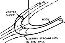
Even more complicated situations occur in wing-fuselage junctions, where the pressures tend to different values away from the junction. In addition, an­other important effect of viscosity must occur in any junction which, in in­viscid flow, would contain a singular stagnation point. This applies in all the cases considered here, where wings with round-nosed subsonic leading edges intersect the wall of a fuselage. The approaching boundary layer along the fuselage will not be able to run up against the adverse pressure gradient to full stagnation pressure but will separate before it reaches the leading edge.

At high-enough Reynolds numbers, the resulting threedimensional separation surface may be a vortex sheet originating from a separation line on the fuse­lage, which contains a singular separation point upstream of the leading edge

Wing-fuselage interference

Fig. 5.44 Flow near the intersection between a body and a wall

and then continues as an ordinary separation line wrapped around the junction, as sketched in Fig. 5.44. The free edge of the vortex sheet will roll up into cores on either side of the wing. If the Reynolds number is relatively low,

a thin vortex sheet cannot be expected to be an adequate representation of the separation surface, but separation lines as in Fig. 5.44 are likely to persist and vorticity is likely to be concentrated and submerged within the viscous region. In any case, the viscous region near the junction then loses altoge­ther the properties of a boundary layer; and it will change the pressure field throughout the region in a manner quite different from the usual displacement effect of ordinary boundary layers. There is no way as yet of calculating this important effect.

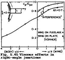
Some experimental evidence on how large this viscous junction effect can be is presented in Fig. 5.45, from tests by L F East И P Hoxey (1968) and H Kbrner

(1969) (see also D KUchemann (1970)). There are two cases and in both a non­lifting, wing-like, body of thickness t is joined either to a plane wall or

LIVE GRAPH

Подпись: Fig. 5.45 Viscous effects in right-angle junctions

Click here to view

to a flat thin plate at right angles to it or to a circular fuselage of radius R. The thickness of the approaching boundary layer is 6 . The pressure co­efficient – Cp (in the region of the suction peak on the wing) is seen to fall below its value Cp0 on the wing far away from the junction as the junc­tion is approached, even when the intersecting wall is flat and would not dis­turb an inviscid flow. In the junction itself, the pressure is only about 3/4 of the undisturbed value on the wing, in both cases with plane walls. The up­per part of Fig. 5.45 shows how the pressure then approaches an inverse square law with distance from the wing. It also shows clearly two suction peaks which, we may infer, are induced by the vorticity concentrated along the se­paration surface, even though we do not know the structure of the separation surface in detail in this flow where it is likely to be submerged within the

viscous region. This feature is not normally picked up in model tests in wind – tunnels such as those in the lower part of Fig. 5.45, and it has been missed altogether in most tests. The magnitude of the viscous interference effect is much the same in both cases shown in Fig. 5.45, although the values of 5/t and of the Reynolds number differ widely.

When the wing joins the curved wall of a fuselage, along which the boundary layer is much the same as that along the plate of the same length ahead of the wing, the lower curve in the lower part of Fig. 5.45 is obtained. The diffe­rence between the two curves there may be interpreted as having been caused by the interference effects in inviscid flow discussed above. We find that this interference pressure is of the same order as the viscous interference in the junction. But the two effects are likely to fade out in different ways away from the junction: the distance from the junction should be measured in terms of the fuselage radius for the interference in inviscid flow, and in terms of the (much smaller) thickness of the approaching boundary layer in viscous flow. Nevertheless, the magnitude of the viscous interference effect is such that it cannot be ignored, and we should not be taken in by any claims to "good agree­ment" between measured results and any calculated for inviscid flow and come to false conclusions as to the accuracy of any such theory – these results should not agree. To throw more light on viscous interference effects, by ex­periment and by theory, is evidently an important task for future research.

The uncertainty about viscous interference should be borne in mind when we now look at some of the meagre available experimental evidence.

Experimental results, which are suitable for our purpose,, have been provided by, among others, D E Hartley (1952) and (1953), J E Rossiter (1959), A В Haines & J С M Jones (1960), T E В Bateman & D J Harper (1960), W R Buckingham (1961), G К Hunt (1963), H Kbmer (1969), J I Simper & P G Hutton (1970), W Schneider

(1970) , and J Bridgewater et al. (1970). Many of these results have not yet been fully analysed, and we present here only a few typical examples, first for symmetrical non-lifting configurations.

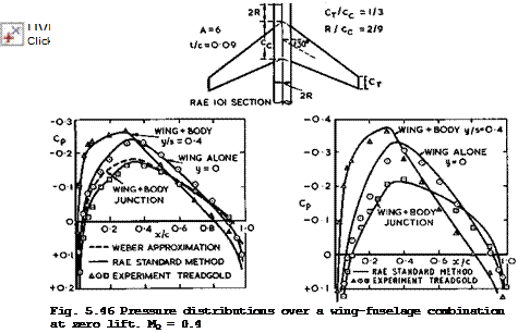
Figs. 5.46 and 5.47 show pressure distributions over a wing of moderate sweep (the same as in Fig.4.60) on a fuselage of simple shape at two subcritical Mach numbers from tests by D A Treadgold (1970, unpublished). All the indivi­dual terms in (5.26) can be identified in this test. The conditions near mid­semispan (y/s = 0.4, triangles) approach those on a corresponding sheared wing (vg). The difference between these curves and those for the centre of the wing alone (y = 0, circles) may be interpreted as representing the kink or re­flection effect (vjn) . The remaining difference between the centre curve and those for the wing-body junction (squares) represents the junction interferen­ce (vj). v„ in (5.26) may be assumed to be small in the present case. The junction ana reflection effects are of comparable magnitude in this example but of quite a different nature. The results calculated by the RAE Standard Method (using sources along the axis of the fuselage to determine Vj) give an adequate overall representation of the various effects but there are discrepan­cies in detail where the available evidence is not sufficient to tell whether they are caused by possible uncertainties or inaccuracies in calculating the inviscid flow, or in the compressibility effects, or in leaving out effects of viscosity, or in the experiment itself. The discrepancies are large enough at the centre section at the higher Mach number (Fig. 5.47) to infer that the compressibility factors used are probably not adequate. Also, the pressure along the junction (in Fig. 5.47) should be represented better by Weber’s me­thod, using sources over the surface of the fuselage, than by sources along the axis, although the calculated curve then lies further away from the mea-

Подпись:

Wing-fuselage interference Подпись: LIVE GRAPH Click here to view

The Design of Classical and Swept Aircraft

Fig. 5.47 Pressure distributions over a wing-fuselage combination at zero lift. Mq — 0.8

sured points. Perhaps, this difference may leave room for the effect of vis­cosity. Obviously, more detailed tests and calculations are needed to get all the physical effects into focus. This holds also for all the further experi­mental and theoretical results below: only the dominant trends can as yet be discerned. An extension of the RAE Standard Method by Sells’s iteration pro­cedure should offer the best prospects for further advances.

The results in Fig. 5.48 illustrate the large changes in pressure which occur when the junction is approached, first for subcritical flow and then for a freestream Mach number where the flow is evidently supercritical over the wing and includes shockwaves. In this particular case, the shockwave has reached the trailing edge in the junction already at Mq = 0.91. We shall see later how this can be prevented by suitable design.

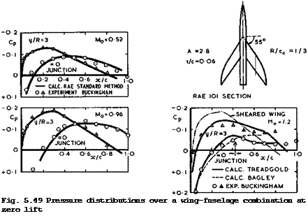
Figs. 5.49 and 5.50 give results for a more highly sweptback wing at three Mach numbers. The flow would have been subcritical over the corresponding in­finite sheared wing even at Mq = 1.2 (as indicated in Fig. 4.8), but it is evidently not on this threedimensional wing. In fact, the junction and reflec­tion effects appear to combine to make the flow supercritical near the junction already at some high-subsonic Mach number, with a shockwave at the trailing edge in the junction. Again, the RAE Standard Method gives an overall descrip­tion of the subcritical flow. At Mq = 1.2 , we can see how much it matters to take account of the reflection effects (Bagley) and to include also distur­bances propagated around the fuselage from the other side (Treadgold); the latter reach the junction at the point marked A.

LIVE GRAPH

Click here to view


Wing-fuselage interference
The Aerodynamic Design of Aircraft

Fig. 5.50 Pressure distributions over a wing-fuselage combination at zero lift

LIVE GRAPH

Click here to view


LIVE GRAPH

Click here to view


Consider now lifting wing-fuselage combinations where the fuselage is at an angle of incidence ctg and the wing at an angle a. A simplified configura­tion like that in Fig. 5.51 may help to clarify the basic physical effects that occur. The wing is assumed to pass through a cylindrical part of the fu­selage, and this cylindrical part is assumed to be long enough that forces over the forebody and over the afterbody have faded out there and do not affect

Wing-fuselage interference

Fig. 5.51 Lift distribution along a fuselage with a wing in midwing position

the region of interference with the wing. This interference can then be thou­ght of again as that between a wing and an infinitely-long cylindrical fuse­lage. As already discussed in connection with Fig. 5.39, the loading over the wing is changed by the presence of the body and, also, the loading is car­ried across the fuselage, extending from some way upstream of the wing leading edge to some way downstream of the trailing edge. If ов ф 0 , the lengthwise loading along the fuselage is roughly as indicated in Fig. 5.51. The download over the afterbody is shown there to be about equal and opposite to the up­load over the forebody. This can only be so in the absence of viscous effects and if the downwash angle induced by the wing trailing vortices over the

afterbody is small enough to be neglected. If the value of oi£ is signifi­cant so that the afterbody is situated in a stream with a downward inclination, then the download will be reduced accordingly and the unstable pitching moment will be smaller than on the fuselage alone. In a real case, the three contri­buting loadings may not be kept neatly apart, as in Fig. 5.51, but it is easy to see how they will merge.

In principle, the loading over a lifting wing-fuselage combination may be de­termined by a panel method, if suitable lifting elements and a vortex wake are incorporated. Again in principle, Weber’s method can deal with general lifting shapes, using singularities within the wing, as in Fig. 5.40, and con­tinuous compensating source distxnbutions over the surface of the fuselage.

An alternative, much simpler and yet quite accurate, method has been developed by J Weber (1969), where the classical aerofoil equation (4.81) is used within the framework of the RAE Standard Method. The compensating source distribu­tion over the fuselage is determined first and from that the downwash over the wing, as in the example of Fig. 5.39. For a wing of given shape, this down – wash may be interpreted as a change of the mean effective angle of incidence and hence of the sectional lift slope a = CL/ae, to be inserted into (4.81). It then remains to calculate the downwash angle induced by the trailing

vortex sheet which should now include vorticity along the fuselage. It is by no means clear how these vortices continue into the wake, i. e. where the Kutta condition should be fulfilled. Following H Multhopp (1941), we may bypass this awkward question by assuming that the cylindrical part of the fuselage behind the wing is long enough for conditions in a crossflow plane there to be interpreted as those in the Trefftz plane at infinity in the wake. Now, the
trace of the fuselage and of the wing in the Trefftz plane can be transformed into a single horizontal slit, with the trace of the fuselage reduced to a slit along the line of symmetry, which does not disturb a flow normal to the slit representing the transformed wing. Following the classical arguments ex­plained in Section 3.2 (see also Fig. 3.2), we can then work out the potential difference across the slit in the Trefftz plane and from there the spanwise downwash distribution a^(y) over the actual wing. It turns out that the complete loading equation is of the same form as (4.81) and can thus be solved by standard methods. There is now a factor 1 + f(y) multiplying the down – wash integral in (4.81), where f(y) depends only on the geometry of the con­figuration, i. e. on the shape of the cross section of the fuselage. For the special case of a wing mounted symmetrically on a circular cylinder of radius R, we have

Подпись: 2Подпись: (5.27)f (у) = 1/ (y/R)

With the loading known over the whole wing surface, the RAE Standard Method can be applied to calculate the pressure distribution approximately.

The distribution of lift over the body which the wing induces cannot be de­termined in the same way as the lift on the wing itself. The trailing vorti­ces from the body cancel each other out in the transformed Trefftz plane, which accounts for the fact that the aerofoil equation remains the same as (4.81).

But the integral of the pressure difference across the fuselage can be related to the potential function in the Trefftz plane and this can be used to obtain an approximation for the loading over the fuselage. The lift is usually high­est in the junction and decreases towards the axis approximately elliptically. For the overall lift Lg over the cylindrical part of the fuselage, A H Flax (1953) has derived the simple relation

Подпись: wingПодпись: CL(y) c(y) f(y) dyWing-fuselage interference(5.28)

when the fuselage itself is aligned with the mainstream (see also A H Flax

(1973) and (1974)).

The original method of H Multhopp (1941) has been extended to include the ef­fects of sweep and small aspect ratios by J Weber, D A Kirby & D J Kettle (1951), and this calculation procedure has also been described in the Data Me­morandum of the ESDU (Anon (1963)). As explained above, the accuracy of the results can be improved by determining the sectional lift slope of the wing by the method of J Weber (1969). A typical example is shown in Fig. 5.52 for the combination of a relatively long fuselage, as in Fig. 5.46, with an unswept wing. The theoretical results have been obtained by the RAE Standard Method with Weber’s extension, making some allowance for effects of viscosity and of wing thickness appropriate to the wing alone. The experimental results (tri­angles and circles, which are mean values for aw = 2.9° and 5.8°) have been obtained by H KBrner (1969). There appear to be some additional effects of viscosity in the case of the wing-fuselage combination, as is expected, but these cannot be identified in detail. As before, the RAE Standard Method gi­ves a reasonable description of the overall features.

The example in Fig. 5.52 illustrates also the strong effect on the lo’ading of the inclination of the fuselage. When = 0, the interference reduces the loading everywhere. When otg = a, so that the fuselage is also inclined to the stream, there is a strong crossflow and hence an upwash along the sides of
the fuselage, which hits the wing and increases the lift on it everywhere. For example, if the wing is put in midwing position on a long fuselage of circular cross-section at the same angle of incidence a, then the wing at the junc­tion is at a local angle of incidence of 2a (the velocity at the sides of a circular cylinder being twice that of the oncoming stream). The resulting lift increase is a general feature of all good theories (see e. g. В Maskew (1970)). Fig. 5.52 also shows the elliptical hole in the spanwise loading

Подпись: Fig. 5.52 Spanwise loadings over a rectangular wing without and with fuselage LIVE GRAPH

Click here to view across the fuselage. Here, is must be borne in mind that this is only a fair­ly crude approximation for the wing-induced lift, defined in principle in Fig. 5.51 but not well defined in many practical cases, and that it rests on the assumption that the Trefftz plane may be placed rather close to the wing where the fuselage is still cylindrical. This difficulty of not knowing how the Kutta condition should be fulfilled applies to all available theories, and so this state of affairs is not altogether satisfactory.

At this point, we must consider in more detail what happens in the junction when the configuration is not symmetrical, as has been implied so far. Al­ready if the wing section is cambered, or if the wing chord is set at an angle to the centreline of the fuselage, then the intersection shapes along the up­per and the lower surfaces are not the same, even when the cross-section of the fuselage is circular. As a consequence, the velocity distributions along the junctions differ from one another and also from the value of vj for the corresponding symmetrical configuration. Similarly, deviations from this value of Vj must occur when the wing is not in a symmetrical midwing posi­tion. These deviations are usually quite large, as can be seen from the sim­ple but typical example in Fig. 5.53 where both wing and fuselage are at zero angle of incidence. Here, C j = 2 Vj for the symmetrical configuration is the difference between the dashed line and the line through the circles. The changes due to the asymmetry introduced—by the low-wing position are seen to be of the same magnitude, and there is a circulation and hence a lift force acting in the asymmetrical junction. In this not-so-severe case of asymmetry,

the flow did follow the intersection lines. This need not be so in more ext­reme cases of high – or low-wing positions, and matters are then even more com­plicated and uncertain (see e. g, D E Hartley (1949)).

Wing-fuselage interferenceLIVE GRAPH

Подпись: Fig. 5.53 Pressure distributions along the junctions between an unswept wing and a cylindrical fuselage. After Hartley (1949)
Click here to view

A practical way of thinking about this effect is to consider again the reflec­tion of the wing in the body wall in the neighbourhood of the junction. There is now, in general, not only a kink in the wing and its reflection in planview, as indicated in Fig. 5.40, but also a kink in frontview, as indicated in Fig. 5.53. The wing has, in effect, acquired an angle of dihedral in that region. The angle of dihedral ф can be defined approximately if the radius of cur­vature of the fuselage is large enough and if the wing thickness is small enough, so that the reflection in a mean tangential plane to the fuselage may be considered. The velocity components induced by kinked elemental source and vortex strips with dihedral and sweep, in incompressible flow, have been cal­culated by G G Brebner & L A Wyatt (1970) (see also D KUchemann (1970)). The results are not altogether obvious and illustrate the complicated nature of the flowfield near these kinks of non-planar singularity distributions. To a first approximation, all the additional kink terms turn out to be proportional to the local source and vortex strengths. The outstanding feature of these results is that, at the kink section, a distribution of sources with constant spanwise strength gives rise to a component of downwash in the plane of symme­try» vz » which has the same direction on both sides of the chordal planes re­presenting the wing with dihedral; and a distribution of vortex lines with constant spanwise strength gives rise to a component of downwash which has op­posite signs on either side of the chordal planes. That is, part of the down – wash due to sources has a characteristic which we normally associate with a vortex distribution, and part of the downwash due to the vortices has a char­
acteristic which we normally associate with a source distribution. In addi­tion, the chordwise velocity increment, vx, due to the vortices has a term proportional to the local vortex strength, which has the same sign above and below the chordal planes, i. e. it is of the form usually associated with a source distribution. Thus the great simplification that linear theory brings to the study of planar wings, namely, the ability to treat thickness and lift effects separately, no longer applies when the wing has a dihedral angle or when it is joined asymmetrically to a fuselage. All these effects are real and strong, and windtunnel tests by G G Brebner (unpublished) on an untapered wing with constant symmetrical aerofoil section and with 45° sweepback and some 30° dihedral have shown that, at and near the centre section, there is indeed an appreciable lift force at zero angle of incidence.

Brebner’s theory has not yet been worked out in more detail and incorporated into the RAE Standard Method, for which it is suitable. These local dihedral und reflection effects matter especially for methods using panel elements on the surface since such elements are then themselves joined at all kinds of angles along the junction, even when the wing is in the midwing position, when the effective angle ф is near 45° for two panels adjoining the junction.

The known analytical nature of the reflection terms is such that the boundary conditions in the junction are violated unless both source and vortex distri­butions have the correct behaviour and the source distribution, in particular, tends to zero in the junction in a certain manner so that the relevant kink terms vanish. It appears that only A Roberts & К Rundle (1972) have consider­ed these matters and that the region of the junction is ignored in other panel methods, regardless of the fact that the interference effects to be computed are largest in the junction. We have already seen from the relatively simple example in Fig. 5.43 that this may lead to serious errors. Until these mat­ters have been clarified and taken into account, any claims, which are often made, that a computer program could deal with wing-fuselage or even more com­plicated configurations of arbitrary shape, cannot be accepted: the essential part of the problem has not yet been tackled.

The effects of significant asymmetries in wing-fuselage junctions are usually detrimental. Effects of viscosity tend to make them worse: if the angle bet­ween the two walls is very obtuse and the junction too shallow, the air may flow across the intersection line and produce unwanted suction peaks or flow separations; if the angle is too acute, the viscous region with its crossflows and concentrations of vorticity may have an even stronger effect and again lead to flow separations, especially when this happens in the adverse pressure gradient near the trailing edge of the wing. For these reasons, fairings are put into the wing-fuselage junction in many actual aircraft in such a way that the walls meet nearly at right angles or are joined by gently rounded panels. The design of these fairings is mostly empirical and crude (but see R Legendre

(1973) ). What is needed is a good design method which can deal with arbitrary cross-sections of non-circular shape, for which an extension of Sells’s iter­ation method of Weber’s theory would be well suited.

We turn now to the question of how wing-fuselage combinations may be designed, following the general principles already discussed in Section 5.3. In addi­tion to the various means for designing wings described there, shaping the fu­selage and especially the junction with the wing is obviously a powerful de­sign tool. This has been recognised for a long time, and farfield approaches have been used to deal with wing-fuselage combinations and other multi-body shapes. Area and equivalence rules have been developed by F Keune & К Oswa – titsch (1952) and (1956), F Keune & W Schmidt (1956), К Oswatitsch (1957), and applied with some success by G Drougge (1957). To shape the combined cross­sectional area of wing and fuselage like those of a body of revolution which gives in theory the lowest wavedrag due to volume at near-sonic speeds, has also been proposed by R T Whitcomb (1952) and by W T Lord (1953). Such shapes usually bring some improvement over plain wings and fuselages, but in Whit­comb’s tests, for example, the drag rise occurred at a Mach Number which was significantly lower than the critical Mach Number of the corresponding in­finite sheared wing, i. e. straight and fully-swept isobars, as in Fig. 5.1(b), had not been achieved. To eliminate the arbitrariness inherent in area rules and to ensure that the design flow is physically realistic and efficient re­quires a nearfield approach to the problem. This has been developed by D KUchemann (1947) and (1957), Anon (1949), J A Bagley (1955), (1956), (1957) and (1961), and R C Lock (1963). ‘ A successful body-contouring method has also been developed by J В McDevitt & W M Haire (1954), and C L Bore (1971) has summarised available design methods and criteria.

If the nearfield approach is used to design for a particular isobar pattern over the wing (Fig. 5.1) by exploiting the interference between wing and fuselage, it is advisable to begin by finding a shape of the intersection line between the two bodies along which the required pressure distribution is ob­tained, because the interference is strongest in the junction: the undesirable distortions are largest there and hence also are the benefits to be obtained when they are eliminated by suitable shaping. If the flow in the junction is right, then the flow is usually nearly right everywhere else on the wing.

In many practical cases, the resulting intersection shape has a characteris­tic feature: the designed fuselage acquires an indentation, it is waisted.

This is a consequence of the fact that the main distortions to be eliminated also have a characteristic feature. This can be explained as follows: when a cylindrical fuselage is combined with a swept wing, the main distortion in the junction arises from the central kink or reflection term vq in (5.26). When the wing is sweptback, vq generally reduces the velocity below the sheared-wing value vg over the front part of the aerofoil and increases them over the rear part, the trend being the same for both thickness and lift effects. Now, if the junction is to be shaped so that vj compensates for Vq, then vj must be positive over the front part and negative over the rear part. As can be seen from the central sketch in Fig. 5.54, a curved wall with an indentation will do just that, whether the mainstream is subsonic or supersonic. Thus designed fuselages will always be waisted and will differ only in detail. Typical shapes for actual designs to compensate for the kink effects caused by thickness only are shown in Fig. 5.55 for a wing of moder­ate sweep at a subsonic Mach Number and also for a more highly-swept wing at a low-supersonic Mach Number. We note that the indentations needed are quite sizeable. This is one of the reasons why conservative aircraft designers have so far not applied this powerful design tool.

Wing-fuselage interference

Fig. 5.54 Velocity distributions along a curved wall

Wing-fuselage interference Подпись: ijK I !
Wing-fuselage interference
Подпись:

Fig. 5.55 Typical shapes of wing-fuselage intersections to compensate for the centre effect due to thickness. Left: for a wing with 9 = 35° and t/c = 0.1 at Mq = 0.85. Right: for a wing with 9 = 55° and t/c = 0.06 at Mq = 1.2 . Dashed lines: cylindrical fuselage. RAE 101 section

For lifting configurations, the specification of sheared-wing pressure dis­tributions in both junctions will, in general, lead to different intersection shapes along the upper and lower surfaces, which do not meet at the trailing edge (see R C Lock, (1963)). A horizontal ledge is then left along the fusel­age downstream of the trailing edge of the wing. Although the effects of such a discontinuity have not been fully explored, they are not necessarily harmful.

The simplest method of designing such shapes is one where the fuselage is regarded as a quasi—cylindrical shape. All the examples described below have been designed in this way. But it is obviously too restrictive to design the fuselage as a waisted body of revolution: The isobar pattern across the body

should also be defined, and this would generally lead to non-circular cross­sections and require an extension of Weber’s theory and also the establish­ment of suitable design criteria for isobar patterns across the fuselage.

Apart from proposing that isobars may be continued at a high angle of sweep

across the fuselage, leading to a bulge on top of it, neither of these prob­

lems has as yet received much attention. What to do in the important case of supercritical mixed flows involving shockwaves is not yet clear. Obviously, the physics of these flows has to be clarified first – computer programs are not likely to produce the design concepts needed without further thought.

As far as the isobar pattern over the wing is concerned, fuselage shaping allows a much wider ohoioe than the patterns shown in Fig. 5.1. An extreme possibility has been proposed by J A Bagley (1955): to shape the junction so

that Cpj = 0 along it, i. e. vj in (5.26) is to cancel all the other con­

tributory velocity increments. One such shape is shown in Fig. 5.56 for a highly-swept wing at Mq = 1.1. The pressure drag is then zero in the junc­tion itself, but whether a reduction of the overall drag can be achieved depends on the flow over the rest of the wing. J E Rossiter (1957) has cal­culated such flows and found that, for the simple case of unswept wings of constant chord at supersonic speeds, the overall change in drag is exactly zero if small-perturbation assumptions of linearised theory are applied and if the wingspan is large enough so that the Mach line from the apex of the wing root runs across the whole wing and does not intersect the wing tip. Drag increases over the outer part of the wing then cancel exactly the drag reduc­tions in the region of the junction. An overall drag reduction may result if

Wing-fuselage interference

Fig. 5.56 Some junction shapes according to different design methods. Swept – back wing with biconvex section, 9 = 60°, t/c = 0.05, on circular-cylindrical body with d/c =0.3

the wingspan is cut down or if it is assumed that the disturbances from the junction are attenuated with distance from the junction. When the wing is swept, isobars will form closed loops and thus lose sweep somewhere so that the critical Mach number may be decreased just outboard of the junction, even though the pressure drag in the junction may be lower in such a design. Until these matters are clarified further it seems safer to design for isobar patterns as in Fig. 5.1 (b) to (d). The junction shape to give fully-swept isobars over the wing (strictly to give Cpj = CpS) is also shown in the example of Fig. 5.56; this requires a much deeper waist. The junction shapes obtained by the sonic area rule for different aspect ratios of the wing are also indicated in Fig. 5.56. These differ substantially from one another and also from the shapes calculated to give specified pressure distributions.

From a nearfield approach, some of the area-rule shapes may happen to have pressure distributions to give some beneficial effect, but it is difficult to see on physical grounds why they should always do so.

Next, we may briefly consider some experimental evidence to see how effective the nearfield design methods are, first for non-lifting eon figurations. In Fig. 5.57, we repeat one of the pressure distributions (squares) in the junc­tion between a moderately sweptwing and a cylindrical fuselage from Fig. 5.48. This flow is strongly supercritical, and we find from the results in Fig. 5.57 (circles) that this can be converted into a shockless subcritical flow with full pressure recovery towards the trailing edge by a fully-waisted fuselage.

If the bulge at the rear is removed, the resulting half-waisted fuselage (triangles) is naturally less effective: the isobars are likely to remain un­swept over the rear wing near the root and the flow is still supersonic locally (the critical pressure coefficient Cp* = -0.19 for 9 = 0° at Mo =

0.9 , whereas Cp* = -0.48 for isobars which are fully swept at 9 = 40° ), with a shockwave just upstream of the trailing edge. This confirms what we have already noted in Section 5.4 in connection with Fig. 5.27, namely, that rear bodies near the trailing edge may be effective means for eliminating rear shockwaves. This was again confirmed by flight tests by D R Andrews et al. (1956) on the Hawker Hunter aircraft, for which J A Bagley (1954) had designed a bulge over the rear of the fuselage to increase the pressure sig­nificantly over the rear half of the wing root. At zero lift, the whole of the Cd(Mq)-curve was shifted roughly to the right by about AMq = 0.02 when the bulge was added. In practical terms, this means that the Hunter aircraft with bulge had about the same drag curve as the F-86 aircraft, which has a wing with about 5° more sweep (45° instead of 40°) and with about 15% thinner sections (t/c = 0.07 instead of 0.085).

Wing-fuselage interference

The Design of Classical and Swept Aircraft

An example of a more highly-swept wing at low-supersonic speed is shown in Fig. 5.58. The results are to be compared with those in Fig. 5.50 for this

Подпись: Fig. 5.58 Isobars and pressure distributions over a wing with waisted fuselage at zero lift. MQ - 1.2. After Bagley (1955) LIVE GRAPH

Click here to view

The Aerodynamic Design of Aircraft

Подпись: 288

Подпись: LIVE GRAPH Click here to view Подпись: Fig. 5.59 Calculated downwash distributions over a lifting wing-fuselage combination. After Weber & Joyce (1974)
Подпись: Next Page

wing with a cylindrical body, where the flow appears to be supercritical near the wing root. The waisted body in Fig. 5.58 was designed by J A Bagley (1955) to give a pressure distribution in the junction like that over the correspon­ding sheared wing, with the aim of obtaining fully-swept isobars. The results demonstrate that this has been achieved quite satisfactorily. Altogether, we can conclude that the nearfield design concept of straight isobars, based on subcritical sheared-wing pressures, appears to be realistic and successful also for wing-fuselage combinations.

The methods described above can, in principle, also be applied to lifting con­figurations. The interference by the fuselage strongly affects the shape of the wing if this is to carry a prescribed load distribution, as has already been shown in Fig. 5.39 for the case of an unswept wing with flat-plate loa­ding. Fig. 5.59 gives a counterpart of this for the case when the wing is swept. The downwash v (x) has been calculated by J Weber & G Joyce (1974) on the wing surface, off the chordal plane (strictly, at a constant value z/c ■ 0.035) so as to avoid the infinite downwash at the kink of a thin wing. From the values of vz(x) , cambered and twisted wing sections can be derived to give the same flat-plate loading all along the span. The shape of such a sec­tion at the centre of a wing alone will obviously be quite different from that in the wing-body junction. Conversely, a wing of given shape will support quite different loadings in the two cases. In either case, threedimensional effects cause very large deviations from the properties of an infinite sheared wing: the effects of the reflection in the body side and of the fuselage inter­ference are considerable.

There is very little experimental evidence to check design methods for lifting

Previous Page

configurations. We refer here to one of the series of wings with 55° sweep, with camber and twist, which was designed by R C Lock (1963) to have the same chordwise loading all along the span and tested by A В Haines (unpublished) . Linearised theory was used, with some allowance for non-linear effects near the leading and trailing edges. The theoretical and experimental results for the design Mach number Mq = 1.19 are shown in Fig. 5.60. The agreement is satisfactory; the small discrepancies that do occur cannot yet be interpreted

Wing-fuselage interference

Fig. 5.60 Loadings over a sweptback wing at Mq = 1.19, = 0.25 (design).

After Lock (1963) and Haines ‘

in detail. Nevertheless, the possibility of achieving efficient lifting de­signs by nearfield methods has been demonstrated up to low-supersonic Mach num­bers, and we may conclude that the swept wing-fuselage combination is indeed the natural aerodynamic shape for this range of cruising speeds.

The fuselage

5.5 Before we proceed to discuss problems of mutual interfe­rence between the various organs of the classical type of aircraft, we consi­der first briefly some problems of the aerodynamics of the fuselage.

The main purpose of the fuselage is to provide volume. This implies that the flow past it is primarily a displacement flow. If the fuselage carries also lift forces and moments (apart from carrying lift across from one wing half to the other), then these may be regarded, in principle, as unnecessary, uninten­tional, or even detrimental. What is wanted ideally can be explained in a nutshell by the hypothetical case where the volume is provided (economically, in terms of surface area) by a sphere and the lift by an unswept wing of in­finite aspect ratio, i. e. by a line vortex through the middle of the sphere, as treated by J Lennertz (1927). The flow past the sphere induces no upwash along the wing and so it may be argued that the addition of this fuselage does not affect the lift. But there is a streamwise velocity increment and, taking this into account and working out the load distribution over the wing-body combination, F Vandrey (1937) confirmed that the overall lift is the same as that of the wing alone, so that volume is provided without any change of lift: lift is carried across the sphere at 3/4 of the initial value, but this is compensated by an increase in lift on the wing outside the sphere. If, in an­other hypothetical example, the fuselage is assumed to be an infinitely long circular cylinder, then Lennertz found that not only the overall lift remains the same but also its spanwise distribution across the fuselage. These cases conform to Cayley’s principle of providing volume and lift independently. Un­fortunately, there are some, often quite complex, interference effects in re­ality and we shall see below that these simple and attractive arguments are rather misleading and do not apply to real wings.

Consider first the essential displacement flow past a fuselage alone and some of the fundamental features that such flows must have. Fig. 5.29 illustrates

what must happen when a sphere (E Riecke (1888), full lines) or a circular cy­linder (W В Morton (1913), dashed lines) moves from right to left through (in­viscid, incompressible) still air past an observer at rest, the shape of the body being shown at the instant when it passes the observer (see also В Thwai – tes (1960), Section VII.3). We follow the motion of air particles from their

The fuselage

Fig. 5.29 Particle paths in the uniform motion of a sphere, or a circular cylinder, through fluid otherwise at rest

initial positions (A) when the body starts at infinity on the righthand side to their final positions (B) when the body has arrived at infinity on the left – hand side. A particle will first be displaced forwards and sideways, to allow for the passage of the body, and later it will be drawn in behind the body when it has passed. The innermost curves in Fig. 5.29 are the paths of parti­cles which move from infinity to infinity and slide along the body. The other curves describe particles situated away from the axis of symmetry. These paths explain clearly why, in such a displacement flow, the relative velocity between the air and the body is higher at the sides of the body than the speed of the body: air and body move in opposite directions while the body passes by. These particle paths also show clearly the essential difference between twodimensional and threedimensional flows: a twodimensional flow causes a much greater eonmotion and disturbance in the air than a threedimensional body, since the air can escape only to the two sides rather than in all directions.

The same flows as in Fig. 5.29 appear to be steady to an observer placed in the body. Paths of air particles are then identical with streamlines, and we arrive at the familiar streamline patterns which can be found in many text­books. Note that the book by 0 Tietjens (1960) stands out for the excellence of the many accurate streamline patterns shown.

We have already seen in Section 2.2, in connection with Fig. 2.1, how such displacement flows can be calculated by the method of singularities, souraes and sinks being the fundamental flow elements. Distributions of sources and sinks along the axis can be used to calculate the inviscid flow past bodies of revolution, and there are also some alternative methods (see e. g. В Thwai- tes (1960), Chapter IX). In the early days, many investigations were directed towards applications to airships (see e. g. G Fuhrmann (1912), Th von Karman

(1927) ), where it is necessary to deal also with bodies which are inclined to the mainstream. It then turns out that the representation by singularities on the axis has serious shortcomings, and so I Lotz (1931) proposed to put the singularities on the surface of the body. In this approach, source rings or vortex rings may be used in the symmetrical case (see D Ktichemann (1940)), and various practical methods of great accuracy have been developed, among others by F Riegels & M Brandt (1944), F Vandrey (1951), and L Landweber (1951). The panel methods by J L Hess & A M 0 Smith (1967), A Roberts & К Rundle (1972), and M J Langley (1973) are probably the most economical and accurate methods of this kind available at present. Approximate methods have also been deve­loped, and so there are linearised theories for thin bodies (of the kind ex­plained in Sections 2.2 and 4.3) and also slender-body theories for shapes with small surface slopes (of the kind explained in Section 4.3; see also Sec­tions 6.6 and 6.8). Some of these theories can also be applied at transonic and supersonic speeds (see e. g. M M Munk (1934), G N Ward (1949) and (1955), and D J Jones & J C South Jr (1975)). We recall here that the assumptions of slender-body theory imply that the lift at any cross-section of the body dif­fers from zero only where the slope of the surface changes along the body.

Thus an inclined body of revolution with a cylindrical part in the middle car­ries a lift force only along the curved nose part and along the curved rear end. For a closed body, the overall lift forces over the nose, or forebody, and over the rear end, or afterbody, are equal and opposite and thus the body experiences only a moment, in this model of the flow. Despite the crude model, this result is still the main feature in practice, except for viscous effects.

Подпись:
LIVE GRAPH

Click here to view

Подпись: v */Vrt xi 0 The fuselage Подпись: (5.24)

The accuracy of the linearised and slender-body theories can be judged from the results for non-lifting ellipsoids (with axes t, d, and A) in Fig. 5.30, by comparison with exact solutions for inviscid incompressible flow by К Ma – ruhn (1941). Exact solutions by Maruhn and by M Brandt (1944) have also been used in Fig. 5.31 to show that the maximum velocity increment on ellipsoids of revolution in incompressible flow can be approximated by

LIVE GRAPH

Click here to view

The Aerodynamic Design of Aircraft

The fuselage

Fig. 5.31 Maximum velocities and critical Mach numbers of ellipsoids of revolution

up to values of the fineness ratio d/& of about 0.3* This can be used to derive a simple rule for the velocity rise with Mach number (see D Ktichemann (1951)): according to the Prandtl-Glauert analogy, the velocity increment vx in compressible flow is 1/6^ times the velocity increment vxa in incom­pressible flow on an analogous body, obtained by reducing the lateral dimen­sions of the original body in the ratio 3:1. Thus vxa ■ $3/2v ^ ^ (5,24),

and finally xl

The fuselage

This rule is quite a good guide for bodies of revolution. It shows that the velocity increases much more slowly with Mach number on threedimensional bodies than the Prandtl-Glauert rule (vx/vxi “ 1/8) indicates for two­dimensional bodies. Thus critical Mach numbers (shown on the righthand scale of Fig. 5.31) are also relatively high.

Most of the work so far has been concerned with bodies of revolution and with conventional fuselage shapes which have a distinct forebody, then a long cylindrical portion, followed by an afterbody ending in a point. Non – axisymnetric fuselage shapes in inviscid subsonic or supersonic flows can also be treated by a method devised by H Rothmann (1972) and, in particular, the behaviour of the flow near the nose of a blunt body has been investigated among others also by H Rothmann (1972) and by P G Pugh & L C Ward (1970), and that of the flow past various shapes of rearbody by G Schulz & К Wichmann

(1972) . What should be noted is that it is by no means clear that the con­ventional fuselage shape is best suited for practical applications within Cayley*s concepts with regard to volume utilisation and to drag and weight. Detailed proposals for unconventional fuselage shapes have been made by H Hertel (1963) and by E S Krauss (1968) and (1970), which may have advantages and approach an ideal body more closely. These shapes have not yet been worked out and exploited in practice.

Viscosity effects in the flow past fuselages are, in principle, much the same as those discussed already in Section 4.5. D F Myring (1972) has provided a method which corresponds to those developed for aerofoils where, in an itera­tive procedure, the boundary-layer development is calculated first in the pressure field of the inviscid flow and then recalculated, taking account of the displacement thickness. It is especially important in this case to con­tinue the calculation into the wake. It has not yet been possible to put this powerful method fully to the test, largely because of uncertainties in the available experimental evidence. Further experimental work of a more defini­tive nature is needed.

Myring’s method applies to turbulent boundary layers in subcritical flow and largely supersedes the well-known method of A D Young (1939) for calculating the pressure and skin-friction drags of bodies of revolution at zero angle of incidence, in which some simplifying assumptions about the properties of the boundary layer and of the wake had to be made, which can now be calculated. If the boundary layer is laminar, quite accurate methods are available to calculate it (see e. g. N A Jaffe & A M 0 Smith (1972)), which are based on the Mangier transformation that links the boundary-layer equations to those in twodimensional flows (see К W Mangier (1946),* N Rott & L F Crabtree (1952)).

But as in many other cases, we are as yet not very sure about estimating where transition to a turbulent flow takes place and what form it takes. Studies of more complex boundary-layer flows on inclined slender bodies have been made by T Nonweiler (1955). Using general boundary-layer concepts,

J L Hess & R M James (1975) have determined shapes of axisymmetric bodies which have low drag at high Reynolds Numbers.

We have already discussed in Section 4.6 that it is in general not possible to carry out the iterative procedure for the determination of the effects of viscosity when threedimeneionat flow separations occur, mainly because we find it difficult to predict either when and where they occur or what form the separation surface takes. One step in this direction has been done by W Geissler (1972) and (1974), who calculated first the potential flow about bodies of revolution and then the development of the laminar boundary layer by an efficient finite-difference procedure. A condition of numerical stab­ility served as a criterion for separation to occur. As it turned out, the limiting streamlines in the surface formed an envelope, as in an ordinary separation line, when the stability condition was violated, but vortex sheets which should spring from the separation lines were not taken into account. A general method to calculate the flow past bluff bodies with wide wakes has been developed by P W Bearman & J E Fackrell (1975) , using distributions of discrete vortices over the surface. For wake flows see R R Clements & D J Maull (1975).

Some possible flow patterns of separated flows over the nose of a slender body of revolution are shown in Fig. 5.32. The angle of incidence is assumed to be large enough for separation to occur somewhere. If we assume that sep­aration starts at a singular separation point S somewhere on top of the body in the plane of symmetry, several different types of flow, involving bubbles and vortex sheets, seem to he possible at first sight and some are sketched in Fig. 5.32. We are as yet in no position to define any of these flows in detail, nor do we have any criteria to distinguish between them and to pre­dict which of them will occur in a real flow. There is, therefore, no basis for an effective theory. What we may expect is that a flow with vortex sheets only, as in case (c) in Fig. 5.32, may occur if the body is very slender. The vortex cores, in particular, are then left behind in the flow. Such body

Подпись:
vortices are generally an undesirable feature in the aerodynamic design of classical wing-fuselage combinations.

A rough estimate of the overaVl forces and moments acting on a slender body of revolution with vortex sheets only can be obtained from the model which

The fuselageLIVE GRAPH

Click here to view

leads to (4.11) and (4.113) in Section 4.6 (see D Kiichemann (1955), where estimates of the overall drag may also be found). For the two bodies sketched in Fig. 5.33, it has been assumed that separation occurs along the cylindrical part of the body at all angles a (in this figure the lift coefficient has been referred to the base area ird^/4). This may, in fact, happen only at angles greater than 5° or 10°, but then the simple flow model seems to provide an adequate description of the overall properties of the bodies, for the time being.

The crossflow-drag concept discussed in Section 4.6 has been used by H J Allen & E W Perkins (1951) and applied to inclined bodies of revolution. At one time, it was thought that it should be possible to define a non-steady motion of a cylinder of infinite length normal to itself in a twodimensional field, which is equivalent to the threedimensional flow past an inclined body of finite length (see e. g. H R Kelly (1954)). Such an equivalence exists and may usefully be applied in the special case of a slender body in inviscid flow. But it does not seem possible to derive such an equivalence from the Navier-Stokes equations, and thus the crossflow concept becomes doubtful in viscous flows, especially if flow separations are involved.

Flow separations may also occur on the afterbody of a fuselage, especially when it is relatively short or asymmetrically upswept. It is unlikely that the flow will always remain strictly attached right up to a pointed tail, and this casts some doubt on how and where the Kutta condition should be applied on threedimensional bodies. If, on an inclined body of revolution, the flow separates upstream of the tail, the download over the afterbody is likely to differ from the upload over the forebody, and the body as a whole will then experience not only a moment but also a lift force.

Investigations with very instructive results have been carried out by W J Rainbird (1968) on right-circular cones inclined to the mainstream. Circum­ferential t not lengthwise t pressure gradients are the main feature of the flow, and the threedimensional boundary layer develops in a flowfield where the streamlines in the outer inviscid stream are not only curved but also con­verge or diverge laterally, quite unlike the conditions in the flow over in­finite sheared wings. Special threedimensional effects arise on the leeside of the body where the pressure changes in such a way that continuity requires convergence of the outer streamlines in a lateral direction as well as normal to the surface, leading to a thickening of the boundary layer. It is then sometimes difficult to detect where convergence and thickening of the boundary layer ends and where separation begins. Thus the ordinary threedimensional flow separation may be a gradual and often quite steady process in the manner sketched in Fig.2.7. On slender inclined cones, the separation surfaces usually take the form of vortex sheets with rolled-up edges. The flowfield induced by these cannot yet be calculated, and thus the general iterative procedure cannot be completed.

Threedimensional flow separations on more general shapes have been studied by W J Rainbird et al. (1966) and by D J Peake et al. (1972) (see also F R Grosche (1970)), and we quote here some results obtained on a prolate ellipsoid of a fineness ratio Л/d of 6:1, tested when generating lift at subsonic speeds at a relatively high Reynolds number so that the boundary layer was fully turbulent. The example in Fig. 5.34 shows a sketch of the flow, involving two primary vortex sheets on the leeside, and a circumferential pressure distribution at a chordwise station. This is quite different from the first approximation for attached inviscid flow and displays the typical additional

suction peaks induced by the rolled-up cores of the vortex sheets, in the same way as we have seen it in the case of tip vortex sheets in Fig. 4.34. We note that the threedimensional flow in a plane across the body is fundamentally dif­ferent from the well-known twodimensional flow at right angles to a circular

The fuselage

Fig. 5.34 Flow pattern (schematic) and circumferential pressures on an ellipsoid. After Peake et al. (1972)

cylinder, in inviscid or in viscous flow. This confirms that the crossflow – drag concept has no physical meaning. The results in Fig, 5,34 also demonstra­te the shortcomings of the theory based on a model with plane vertical vortex sheets, leading to overall forces as shown in Fig. 5.33: this theory may give a rough estimate of the overall non-linear lift increment, but it cannot pre­dict any details of the pressure distribution like those illustrated in Fig.

5.34. An adequate theory still remains to be developed.

Although threedimensional flow separations on long slender bodies may often be regarded as steady, there is a strong possibility that asymmetric periodic oscillations may occur in the manner discussed in connection with Fig. 2,16, especially if the ordinary separation lines are not fixed along a sharp edge but may move about, which they can do readily when the shape of the body is rounded. These phenomena were studied in classical investigations by W J Rainbird et al. (1966) and by D J Peake et al. (1972) by testing bodies of re­volution with parabolic ogive forebodies and long cylindrical afterbodies, as sketched in Figs. 5.35 and 5.36. Three distinct types of flow were detected over a range of angles of incidence on any given configuration, corresponding to attached flow, symmetric separation, and asymmetric separation. The at­tached-flow regime extended only to small angles of incidence (typically up to a = 3°) and the lift then increased linearly with a and also with Mach number and seminose angle 6 • The onset of flow asymmetry is shown in Fig.

5.35, as it depends on the angle of incidence and on the seminose angle.

Подпись:The fuselage
The Design of Classical and Swept Aircraft

Fig. 5.36 Asymmetric primary separa­tion angles on pointed slender body of revolution. After D J Peake et at.

(1972)

Fig. 5.36 illustrates how the primary separation lines move about on the port and starboard sides (there are also secondary separation lines, which are not shown here; see Section 6.3). Asymmetric flow conditions are associated with side forces, and oscillations of the sideforce may reach peak-to-peak amplitu­des as high as _ 0.3 of the mean lift force at a – 25°. Increasing either the nose angle or the Mach number resulted in a reduction of the sideforce. These flows have also been discussed by H C Kao (1975) on the basis of the crossflow concept of Allen & Perkins but, as discussed above, the physical validity of this concept is suspect.

The type of flow with vortex-sheet separations from inclined slender bodies may readily persist in the same form also at supersonic mainstream speeds as long as the Mach-number component normal to the highly-swept isobars does not exceed unity. The two vortex cores may then be so close together that the component Mach number becomes sonic first in the downward flow between the two cores (that is, not on top of the vortex sheet, as in Fig. 2.13). Beyond that condition, a mixed flow exists, which corresponds to a local supersonic region terminated by a shockwave. A sketch of such a flow is shown in Fig. 5.37, as it has been observed by R H Plascott & D A Treadgold (1955). The shockwave lies above the body between the vortex cores and is inclined at a slightly smaller angle to the mainstream than the body itself. Underneath this shock­wave and between the feeding sheets extends a region in which the flow is sub­sonic in character.

All these results were obtained under static conditions with a model held in a fixed position in a windtunnel. In some practical applications, the rate of change of the angle of incidence may be so rapid that dynamic effects become significant. The positions of the separation lines then change also with time and hence the lift and side forces. In tests by R Fail (1968, unpublished), where a body of revolution was accelerated rapidly from zero angle of inciden-

The fuselage

Fig. 5.37 Skeleton of flow past an inclined cone-cylinder body of revolution at Mq = 2.5. After Plascott & Treadgold (1955)

ce up to 90° and then back again, a strong hysteresis in the forces was obser­ved, depending on the frequency and on whether the angle of incidence was in­creased or decreased. While the angle is increasing, there is an excess nor­mal force over that in the static case but, for decreasing angle, the normal force is appreciably less than in the static case.

Some special designs

5.4 In this Section, we mention very briefly some special means which might be used in the design of swept wings to improve their characteristics. Most of these have not yet been exploited and applied in practice.

One possibility is to blow a thin jet out of a slot along the tip edge, as proposed, among others, by E Carafoli (1970). This will extend the tip vortex sheets (see Section 4.6) further out laterally and thus achieve an effectively larger span, which may have a beneficial effect on the vortex drag and also on the isobar pattern in the tip regions of a lifting wing. This scheme may be regarded as a "threedimensional jet flap". It has been proposed also for slender wings, with blowing from all edges; this will be discussed in Section

6.4.

Another possibility is to make the trailing edge blunt. This has been inves­tigated extensively on twodimensional aerofoils (see e. g. J F Nash (1965),

M Tanner (1973) and (1975)). The main beneficial effects can be expected to occur at transonic speeds in mixed flows: the slope of the rear upper surface can be reduced in this way, and the pressure to be reached at the trailing edge can be lower, because the flow can expand further around the base and reach the undisturbed mainstream pressure through a pressure rise downstream in the wake where the base separation bubble closes. In return, this must be paid for by a pressure drag on the base (more about base flows can be found in Section 5.9). Various means for reducing the base drag have been reviewed in detail by M Tanner (1975), including splitter plates, splitter wedges, ser­rated or segmented trailing edges, and base bleeds. Many of these have rea­ched a promising state of development and may find useful practical applica­tions, although it is not yet always clear how they might be combined with high-lift devices of variable geometry. The base drag may also be relieved by base burning, that is, by modifying the base flow by heat addition, as ana­lysed by E G Broadbent (1973) (see also Section 5.9). Another possibility of reducing the base drag may be the incorporation of oonioal out-outs, as pro­posed by D KUchemann & J Reid (1960) and sketched in Fig. 5.26. Some parts

of the wing surface then retain the same low slope and pressure as on a wing with a blunt base. These parts end in a sharp vertical edge. Behind the apices of the cut-outs, the surface slopes down to a sharp horizontal trailing

Some special designs

/


Some special designs

Fig. 5.26 Sketch of vortex sheets Fig. 5.27 Sketch of a sweptback wing shed from a wing with conical cut-outs with an array of bodies along the

trailing edge

edge, bounded on the sides by triangular vertical surfaces. If properly de­signed with a high enough angle of sweep, it can be expected that conical vor­tex sheets will be shed from the top edges of these vertical surfaces. The rolled-up cores of the sheets will induce a downward flow to fill the region over the cut-outs and, in this different flow mechanism, the boundary layer will not have to run up against a steep pressure gradient, as on conventional wings. But the rolled-up cores will also induce some suction over rearward­facing surfaces and so there will be some drag penalty. The greater wing thickness provided by this scheme or by a blunt trailing edge should bring some structural benefits, and it should be possible to combine conventional high-lift devices with this scheme. However, very little is as yet known about how any of these devices work on threedimensional wings.

Under supercritical conditions, vortex flows as in Fig. 5.26 should make it impossible that strong rear shockwaves (such as (2) and (3) in Fig. 4.69) move towards the trailing edge and cause a rear separation with all its undesirable consequences (see Section 4.8). A similar effect may be achieved by a series of bodies, as sketched in Fig. 5.27. These may be put mainly on the upper sur­face; they may begin at or behind the maximum thickness or the crest and ex­tend beyond the trailing edge. That the flow field induced by such a rear body should break up rear shockwaves and thus improve the buffet characteris­tics was suggested by D E Hartley (1953) and then applied to the fin-tailplane junction of the Hawker Hunter aircraft and successfully demonstrated in flight. That several bodies at the trailing edge of a wing, as in Fig, 5.27, can have a similar beneficial effect was demonstrated in flight in 1956 on the Gloster Javelin aircraft (see e. g. Anon (1958)). These "KUehemann carrots" are also known as "Whitcomb bodies", after R T Whitcomb who later made similar propo­sals. Although such bodies can be successful in improving the off-design be­haviour of wings, they cannot necessarily be regarded as permanent features of properly-designed supercritical wings.

Подпись: / Fig. 5.28 Sketch of vortex sheets shed in a combined flow

Another design possibility again involves vortex flows. It concerns cranked wings and may be regarded as an alternative to the design concepts discussed above in connection with the Victor aircraft. As already stated, sweptback wings with large centre chords run counter to designs with uniform spanwise loading. If it is considered too difficult in a particular case to load up the centre part of a cranked wing, keeping the classical attached aerofoil flow, and if a thick inner wing is not wanted, the possibility might be con­sidered of taking the serious step of giving up the concept of maintaining the same type of flow over the whole wing throughout the whole flight range. In­stead, we think of combining two different types of flew on the same wing. We want to consider, as an example, the possibility of combining the classical aerofoil flow over part of the wing with the slender-wing flaw with coiled Vortex sheets above another part of the wing (see Section 3.3, Figs. 3.5 (b) and 3.6). We do not want to advocate its application but only speculate on what the properties of such "crossbreed" wings could be as compared with those of "pure" designs (see D Kuchemann (1971)). We are aware from the outset that such designs must be more risky and are more likely to fail.

A simple way of thinking about the flow pattern is to take a typical sweptback wing of high aspect ratio and moderate angle of sweep, without fuselage. In the attached flow, the central kink effects extend about a half to one chord outwards from the centreline. Next, take a slender wing with sharp leading edges and an aspect ratio of about unity. The size of the slender wing could be such that the semispan is again between half and one chord of the swept wing. This slender wing is put in front of the swept wing to "cover the kink region", as it were, as sketched in Fig. 5.28. The combined flow past a lif­ting wing of this kind has coiled vortex sheets from the leading edges of the slender inner wing. These should then be cut at the crank where the two wings join in such a way that the entire sheets separate from the wing surface. Spe­cial means might have to be taken, if necessary, to bring this about. The vortex sheets from the slender part are then continued downstream as free vor­tex sheets. Each has two cores along the two free edges. The bound vortices on the slender part are then continued on the swept part behind. There are two possibilities: first, the bound vortices (which give circulation) could

be bent forward and linked across the centreline so that no trailing vortices with the wrong sign are shed from the combined wing. In this case, there may
even be a hump in the spanwise load distribution, leading to intensified local shedding of vorticity and the formation of double-branched cores, and a rela­tively large downwash in the middle region. This flow is sketched in Fig. 5.28. Second, the shape of the wing could be such that the bound vortex lines are not linked across the middle. This would lead to part-span shedding of vortices of the wrong sign and hence to relatively large drag forces due to lift. This should be avoidable by careful design. Also avoidable, but pro­bably of minor importance, should be the cutting of the trailing vortex sheet by the intersection of the attachment lines with the trailing edge, because the outflow away from the attachment lines on the front part of the inner wing may become weaker over the rear part, and the attachment line may have disap­peared in the trailing-edge region. In other words, the flow could be largely parallel to the freestream direction when it reaches the trailing edge. It ought to be possible, therefore, to design a combined wing to have a smooth flow which remains attached not only over the inner wing but also over the whole of the outer swept part of the wing.

With regard to the possible behaviour at low speeds, consider first the con­dition at high lift for the case without flaps. With the front wing, more lift should be generated in the middle part and the usual hole in the spanwise load distribution on conventional sweptback wings eliminated. To achieve this the non-linear lift resulting from the flow separation along the leading edge of this part of the wing would seem to be essential. (Attached flow over the inner wing would produce an even bigger hole in the spanwise (^-distribution) This improvement in the spanwise loading should imply that the tips can be un­loaded, for a given value of the overall lift coefficient. Therefore, some improvement or delay with regard to tip stall, pitch-up, and wing drop may be expected. Even so, it seems probable that such wings would pitch up when they do stall, since the inner part of the wing is virtually "unstallable". In any case, the pitching-moment curve is not likely to be linear. Alternatively, the outer wing in the upwash field from the vortices of the inner wing could carry more lift, for a given angle of incidence. What really happens should be investigated on a complete model with tailplane because the large changes in downwash at the tail should also be taken into account, so that values of forces and moments can be obtained under trimmed conditions.

High-lift devices for the outer swept part of the wing can be designed large­ly in the usual way, especially leading-edge devices. Trailing-edge devices should be effective all along the span. Area increases needed may be smaller for the combined wing and could be tailored to better effect. It may be pos­sible to reduce the angle of sweep of the trailing edge of the inner part of the wing, since this may not have quite such detrimental effects as on con­ventional sweptback wings.

The main disadvantage of the combined flow is the existence of free vortices quite close to the aircraft surfaces. There are no means of controlling the position of these free vortices, and induced yawing and rolling moments must be expected to be especially sensitive to the location of the free vortices relative to the fin. A high tail position may also lead to uncertain proper­ties. To resolve these problems would require dynamic testing since static derivatives are not likely to reveal all the possible adverse effects.

With regard to the possible behaviour at high speeds, consider first the con­ditions in subcritioal flow. It is possible to design for an attached flow over the inner wing. The advantages would then lie in an improved isobar pat­tern, and camber and twist would have to be incorporated to achieve a high

local critical Mach number, combined with good lift production. But this can be done for only one specific design condition.

The other possibility is to make the leading edge sharp and to let the flow separate from the leading edges of the inner wing also at high speeds. This should again lead to a high local critical Mach number. As will be described in Section 6.3, the flow need not be conically supersonic anywhere even at an angle of incidence of about 20° and a freestream Mach number of 1.1 (see e. g.

J H В Smith & A G Kum (1968)). There is also the advantage of having a near­ly parallel flow inboard of the attachment lines and especially near the cen­treline. Perturbation velocities can be expected to be small, therefore, and the inner wing should nevertheless show good lifting characteristics. How­ever, the flow will go supercritical near the centreline in some conditions.

Consider now supercritical conditions. If the flow is kept attached along the leading edges of the inner wing, an isobar pattern similar to that in Fig.

5.1 (d) could be a worthwhile aim. If the flow is separated, the main advan­tage would be that there is no need for an inward flow behind the leading ed­ges on the inner, conical, part of the combined wing. Hence there is no need for the front leg (1) in Fig. 4.69 of the shockwave pattern usually found on sweptback wings. There is still an inward flow over the swept and rounded parts of the leading edge. However, this does not meet a solid wall but vor­tex sheets instead. These may give way: there is a "soft" rather than a "stiff" interaction, in the manner of the flow element sketched in Fig. 2.13. The shockwave over the outer wings could be designed to be fully swept and then to fade out inboard. However, a relatively weak shock may be needed over the rear part of the inner wing. With such shocks present, there will be a largely unknown interaction between them and the free vortices; this could cause vortex breakdown (see e. g. E P Sutton (1955)). On the other hand, there could be a considerable relief on the outer swept part of the wing by loading up the middle region. Thus severe buffeting, wing rocking, and wing dropping could be delayed to higher lift coefficients or Mach numbers. Also. manoeuvre flaps could be very effective, especially trailing-edge flaps over the inner wing. Any such advantages may have to be paid for by an increase of the lift – dependent drag, as a result of the more complicated trailing-vortex system. A combined wing as in Fig. 5.28 is sometimes described as a sweptback wing with strokes. M Lotz (1974) has considered the design of supercritical wings with strakes in some detail. The possible improvements in manoeuvrability at high- subsonic speeds are seen as the main advantage of the central strakes, accor­ding to W Staudacher (1972).

A fuselage may be combined with such a wing without upsetting the desired flow characteristics. There is also the possibility of giving the front wing suf­ficient length and volume so that it may by itself form the front part of the fuselage.

Altogether, the advantages of combining two different types of flow on one wing all seem to stem from the elimination or the reduction of the kink effect near the centreline of a sweptback wing or near the body junction. This kink effect is replaced by a soft interaction at the joint between the two wing parts. We are not yet in a position to predict the flow in that region in any detail. A theory is not yet available and will be difficult to develop becau­se the flow is essentially non-conical and non-slender in that region. If we want to find out what happens, a good experiment would seem to be the best way

We have been concerned here only with the reduction of the central kink effect hut it should he pointed out that one could think of a corresponding treatment of the tip regions of a swept wing. The sketch in Fig. 5.28 shows tip vortex sheets. These could result from deliberate design. A discontinuity may be introduced in the leading edge near the tip, say, one chord inboard from the tip or less. One could make the leading edge aerodynamically sharp outboard of that discontinuity and produce leading-edge vortex sheets there. Again, this would be a combination of vortex flows and attached flows. In fact, on such a wing, there would be flow separation along the inner part of the lea­ding edge, followed by attached flow along the leading edge of the middle part of the wing, and separated flow again along the leading edge near the wing tips. All the flow separations would be fixed and controlled. Lift would be maintained over the tip region at low speeds as well as at high speeds, in­cluding supercritical conditions. Any pitch-up tendencies at the final stall might be reduced. Wings with mixed flow of this kind may, therefore, be worth further detailed investigation.

An alternative, and probably more meaningful, way of looking at mixed designs as in Fig. 5.28 is to regard them as yet another design condition of a varia­ble-geometry aircraft, now for flight beyond the buffet boundary, where a con­ventional aircraft design will have an uncontrolled disorderly flow like that in Fig. 4.71 with several separations. The design objective would then be to fix the separation lines and to control the separated regions so as to arrive again at a well-behaved type of flow. We shall have to think about such multi­flow wings much longer before we know well enough how to design them.

Threedimensional wings

5.3 All the design aims have been specified so far in terms of the nearfield of the flow; in fact, in terms of the pressure dis­tribution over the surface. But it is often claimed that, to reach the de­sign aims, a farfield approach, as explained in Section 3.1, would be suffi­cient and simpler and indeed more efficient, since it would allow the "mini­misation" of the drag and the "optimisation" of the configuration, at least for inviscid flow. A balanced discussion of these claims may be found in the review by J A Bagley (1961). At subsonic speeds, the farfield approach takes note only of the spanwise lift distribution (by a consideration of the flow in the Trefftz plane). At sonic and supersonic speeds, this approach takes account also of the wavedrags. The sonic and supersonic area rules, descri­bed in Sections 4.8 and 4.9, appear at first sight to define the shape of a configuration. We have, in fact, used the general drag relation (4.140) with convenient values for the drag factors to define at least the shape of boxes into which configurations should be fitted to be aerodynamically efficient (see Fig. 4.76). But it is doubtful whether we can usefully go much further than that since designs by any of the area rules only have many shortcomings. Firstly, the drag values implied, and hence the "optimisation", may be quite inaccurate because the assumptions upon which the rules are based are not ful­filled. Even when they are, as on some slender wings (to be discussed in Sec­tion 6.7), the sonic area rule may lead to gross errors. Secondly, the shapes are not defined uniquely, and the fewer the geometrical constraints imposed, the smaller is the guarantee that the optimum shape will actually be meaning­ful (i. e. that it will not have negative thickness or some similar geometri­cally absurd feature). Thirdly, and most importantly, there is no assurance that the flow past any of the resulting shapes is physically possible: unless the pressure distribution over the surface is known and a check made whether or not a viscous region can be fitted underneath the inviscid flow (as explai­ned in Section 4.5), we do not have a physically meaningful solution. For these reasons, the nearfield approach is indispensable. It is adopted here but this, in turn, implies that the flows and shapes obtained, however rea­listic, are not necessarily the best and most efficient. This is a physical dilemma which cannot readily be resolved. However, whenever possible, the far­field approach can be used to give some guidance and, in this sense, the two approaches are complementary.

In the nearfield approach, an isobar pattern over the wing surface is specifi­ed, at least over the upper surface, such as one of those shown in Fig. 5.1.

To calculate the wing shape, the RAE Standard Method with the iterative exten­sion by С C L Sells (1974) and (1976) can be used for subcritical speeds and some linearised theories for sonic and supersonic speeds. This means that supercritical isobar patterns like case (d) in Fig. 5.1 cannot yet be dealt with. The procedure is the same as that outlined in Section 5.1 and as applied

to the case of a twodimensional aerofoil in Fig. 5.2. For threedimensional wings, the main design parameters are now not only the chordwise thickness and camber distributions of the aerofoil sections at various stations along the span but also the twist distribution a, j.(y) along the span and the planform shape itself, that is, the spanwise distribution c(y) of the chord. Since the relations for the pressure are basically made up of twodimensional terms and of kink and tip terms, where the pressure is proportional to the local source and vortex strengths, we can expect that any of the design changes nee­ded to depart from the undesirable isobar pattern in case (a) of Fig. 5.1 will exhibit some common features. To explain these clearly in a simple form, we consider the central region of a sweptback wing of constant chord and infinite span and demand that the wing should be designed to eliminate the kink effect, i. e. the isobars should be straight and parallel from the sheared part of the wing right up to the centre line.

Regarding thickness effects at zero lift, we recall that the velocity at the centre section of a wing with constant sections is always higher than that on an infinite sheared wing behind the crest and lower upstream of it, as is de­monstrated by the typical example in Fig. 4.19. To remedy this, and to reach the same velocities as over the sheared part of the wing, it can readily be seen that the thickness and surface slope should be reduced over the rear part of the centre section and increased over the front part, that is, the position of maximum thickness should be shifted forward. This implies that the section modifications should all look like that in the example*) in Fig. 5.17 (1) (ba-

Threedimensional wings

( I ) SAME PRESSURE DISTRIBUTIONS AT ZERO LIFT

Подпись: Fig. 5.17 Section shapes at the centre section of a sweptback wing with <p=35° (full lines), which correspond to the RAE 101 section with t/c = 0.1 on an infinite sheared wing (dashed lines)

(2) SAME CHORDWISE LOADINGS AT CL«0-3

sic section RAE 101, q> = 35°, t/c = 0.1, M_ = 0.85). This has been calcula­ted from (4.88) with appropriate compressibility factors. Such thickness modifications have been first proposed and determined by D Ktlchemann (1974).

F Ursell (1949) has rewritten (4.86) in the form

*) . .

If an arbitrary velocity distribution is chosen, the section shape obtained may not be physically sensible, even in this nearfield approach: the applica­tion of (4.88) will lead to aerofoils that close at the trailing edge, but it does not guarantee positive thickness at all points – the contours of the up­per and lower surfaces may cross each other. We also note that such section modifications happen to make the cross-sectional area distribution "smoother".

!!t = / 3zt(x,) dx’ vx(x»°>0)

dx ° irf(^) J Эх x – x’ – Vq cos ¥> f (<P) (5.17)

Threedimensional wings Threedimensional wings Threedimensional wings

and obtained an explicit expression for the section shape of a wing having a specified velocity distribution vx(x) at its centre section:

and f(<p) is defined by (4.87). Explicit solutions can be obtained also for special aerofoil sections, such as the biconvex circular-arc section (see S Neumark (1947), D Kiichemann (1947)). This leads to some simple approximate formulae for estimation purposes, derived for small angles of <p but appli­cable up to angles beyond about 60°: the thickness-to-chord ratio is to be changed roughly according to

(tje) = 1 – (it – l)(<p/ir)2 ; (5.20)

and the forward shift of the position of maximum thickness is roughly

x/c = <p/2tt ; (5.21)

where the suffix 0 denotes the basic section on the sheared part of the wing.

Threedimensional wings Подпись: (5.22)
Threedimensional wings

It should be noted that, although a wing designed in this way may have straight isobars and thus delay the onset of supercritical flow, the central region will still, in general, carry a non-zero normal-pressure drag. The pressure distribution of an infinite sheared wing will give zero drag only on the shape of the sheared-wing section itself and not on the modified section. It is possible, however, to design centre-section shapes which have a low or even zero drag. J Weber (unpublished; see J A Bagley (1961)) has calculated the centre-section shape for which the velocity increment is constant along the chord, so that the local sectional drag is zero for this closed section. This is a perfectly reasonable shape defined by

where 8 is given by (5.19). But the drag of sections along the span for у > 0 may then be greater than before the modification and the overall drag

in the central region may be the same as before. These matters have not yet been investigated in detail.

Regarding next lift effects on wings of zero thickness, we recall that the load along the centre section of a flat wing is always higher over the rear part and lower over the front part than that over an infinite sheared wing,

as is demonstrated by the typical example in Fig. 4.23. To remedy this, and to reach the same loading as over the sheared part of the wing, it can readi­ly be seen that the chordwise slope of the camberline of the centre section must be increased towards the leading edge, that is, the centre section should have negative camber and positive twist. This means that the centre modifi­cations should all look like that in the example in Fig. 5.17 (2) (C^ * 0.3;

Ф = 35°; Mq = 0.85; with thickness of basic RAE 101 section with t/c =0.1 superimposed). As usual, we consider thickness and camberline modifications to be additive, to a first order.

The application of this kind of camber and twist has been proposed by D Kiiche – тпяпп (1950), and the shape for the particular aerofoil considered here has al­ready been derived in Section 4.4 and is given by (4.97). G G Brebner (1952) provided analytical solutions for a whole family of camberZines with loadings of the form

i(x, y) – sin irn jcj X j + C2 J, (5.23)

where and C2 are constants related to the maximum camber and to its

chordwise position. The parameter n(<p, y) is given by (4.105) and the para­meter m, with 0 $ m $ 1, describes the shape of the camberline. This fa­mily of camberlines is shown in Fig, 5.18. In twodimensional flow, the case

Threedimensional wingsLIVE GRAPH

Click here to view

Threedimensional wings

O 0*2 0-4 x/c О 6 0 8 l-o

Fig. 5.18 The shapes of Brebnerfs camberlines

m = 0 corresponds to a uniform loading along the chord and is thus the same as that of the NACA camberline designated a = 1 (see I H Abbott et a7.(1945)); and the case m = 1 corresponds to a flat plate. At the centre of sweptback wings, the case m = corresponds to (4.97). Brebner derived the complete set of aerodynamic properties for this family, including expressions for the no-lift angle and the centre of pressure. These camberlines may be used for design purposes, within the method described in Section 4.4, when the shape of the section on the sheared part of the wing is not flat but cambered, as it will usually be. Further work on designing cambered wings to give uniform loading along the span has been done by T Kawasaki (1965) and by T Kawasaki &

M Ebihara (1966).

An extensive framework of methods for the design of cambered wings with subso­nic edges in inviscid flow at sonio and supersonic speeds has been developed and reviewed by R C Lock & J Bridgewater (1967). In these methods, the per­turbations in the flow are assumed to be small and shockwaves are not admitted. Thus wings with supercritical pressure distributions cannot be treated. The camberlines and distributions obtained are of the same type as Brebner’s solutions for subsonic speeds. Since centre and tip effects may be very pro­nounced at sonic and supersonic speeds, camber and twist needed to compensate for them may be large. Modifications of the thickness and camber shapes at subcritical speeds, as indicated in Fig. 5.17 may also be quite considerable. This’ must imply that the supercritical development of the flow past such sha­pes may not be the same as that on the corresponding twodimensional aerofoil, even if they all start from the same subcritical pressure distribution. These matters have not yet been resolved.

The shape of the centre section of swept tapered wings with a linear chordwise load distribution has been calculated by J C Cooke (1958). G M Roper (1959) has developed a method for determining camber shapes to give a specified loa­ding over sweptback wings with subsonic edges at supersonic speeds. Quite generally, thickness modifications and the application of camber and twist can be carried out all along the span of a swept wing. At subcritical speeds, the tip regions can again be treated like the centre section of a halfwing of op­posite sweep. If the velocity increments due to thickness at the tip are to be equal to those of an infinite sheared wing at subsonic speeds, the resul­ting shape will have a considerably larger thickness-to-chord ratio than the original section because of the reduction factor 0.7 in (4.91), as explained in Section 4.4. However, the nose thickness then becomes rather small and the trailing-edge angle large since the position of the maximum thickness will be shifted backwards, according to (5.21). If t/c is kept the same at the tip, then the velocity will be reduced and hence some isobars will be closed before they reach the tip. An alternative method of improving the tip region which leaves the thickness distributions of the sections unaltered, is to aurve the leading edge (parabolically, say) from some point on the leading edge inboard of the tip (which may be about 1/4 of the local wing chord away) to a stream – wise tip at the trailing edge, in the manner indicated in Fig. 4.66, for ex­ample. The idea behind such a shape, as proposed by J Weber (1949), is to produce the unavoidable tip thrust (see e. g. Fig. 4.33) not by increasing the suction but by reducing the positive pressure near the attachment line along the leading edge. The isobars may then roughly follow the planform shape and acquire higher angles of sweep in the tip region than on the sheared part of the wing, as sketched in cases (b) and (c) in Fig. 5.1.

All these design modifications can be applied to the wing at one specific de­sign point only, i. e. specific values of Cl and Mq, for a given planform. Further, part of the (often large) angle of twist is needed simply to compen­sate for the non-uniformities in the spanwise loading, that is, to load up the central part and to unload the tip regions. This purpose can also be achieved by a planform modification, for example, by reducing the chord in the central region, as compared with an elliptic planform, say, and increasing it in the tip regions. In principle, this has the considerable advantage that the span – wise lift distribution CL(y) can be designed to have a given shape at all CL-values within the linear range. Cl may be kept constant along the span, if so desired. This implies, in turn, that camber and twist are then requir­ed only to look after the chordwise loading. Planforms to give constant Cl may also have a beneficial effect on the longitudinal stability and on the stalling characteristics.

Planform modifications as a possible means of swept wing design were proposed as soon as the peculiarities of the loading over sweptback wings (see e. g.

Threedimensional wings

Fig. 4.24) were recognised, by Lemme and Luckert (unpublished AVA Reports (1943) and (1944); see R Seiferth (1947)). Similar planform modifications were incorporated into the Republic XF-91 aircraft (see R McLarren (1949)), but no results are available. The early methods were not very accurate in taking account of the centre and tip effects, but now better methods such as that described in Section 4.4 can be used to calculate the planform shape. In particular, (4.56) or the more general form (4.81) can be regarded as a rela­tion for determining c(y) for given values of С^(у), a(y), and <p. Since the sectional lift slope a depends on y/c and thereby on the unknown chord, the solution can only be obtained by iteration in successive approximations, but this presents no problems and the iteration converges rapidly. The aspect ratio of the wing and the overall C^-value cannot be prescribed but come out at the end. This method has been applied by D KUchemann (1950), and some re­sults have already been shown in Fig. 4.21. Many applications have been wor­ked out by G G Brebner (1954) and (1956), and some of his results are repro­duced in Figs. 5.19 and 5.20. He found that sweptback wings acquire inverse taper in the central part as the aspect ratio and the angle of sweep are in­creased. For example, for a wing with constant C^, inverse taper is just a­voided when A = 2 for <p = 40°, and when A = 1 for q> = 60°. For higher va­lues of A and/or ф, there comes a point where the chord at the centre is zero. This happens, for instance, when A = 10 and <p = 60°. We find as a general result that the conventional planform taper of unswept wings is detri­mental on sweptback wings and only reinforces the shortcomings. The opposite applies to sweptforward wings, where conventional taper has a beneficial effect.

Fig. 5.19 Some of Brebner’s plan – forms to give constant CL along the span on sweptback wings. <p = 40°

Fig. 5.20 shows some unconventional planforms which also give a constant CL – value along the span. These include a sweptforward wing. It seems strange that forward sweep has been largely neglected so far, even though an aircraft with sweptforward wings, the JU 287 with 4 turbojet engines, was designed by H Wocke and flown successfully as early as 1944. Forward sweep has many ob­vious aerodynamic and structural advantages, and it should be possible to overcome difficulties in the aeroelastic behaviour. The other planforms in Fig. 5.20 have not yet been applied in practice either; they deserve to be taken more seriously. Note that the overall lift slope CL/a of the swept­forward wing of A = 3>3 is the same as that of the sweptback wing of A = 4.8. The nominal (midchord) angle of sweep is the same for all planforms shown in Figs. 5.19 and 5.20, but this does not mean that the critical Mach numbers and the wing characteristics beyond that need be the same. In the absence of any detailed information, we cannot yet say whether unconventional planforms, if fully developed, would offer significant advantages over the conventional sweptback wing.

In two of the cases in Figs. 5.19 and 5.20, alternative planform shapes have been drawn (dotted lines) where only the beading edge is curved and the trailing edge is kept straight. To a first order, these planforms have the same uniform CL_distribution and only second-order effects, taking account of varying sweep angles near the tips, are likely to reduce Cl a little in the tip regions. These planform shapes with straight trailing edges may have constructional advantages and may ease the installation of high-lift devices.

As it happens, this curved leading edge has the kind of shape which has been described above as being beneficial for the isobar pattern due to thickness.

We now find that it is also beneficial for lifting subsonic wings. Further­more R C Lock (1957) and (1961) has derived similar curved leading-edge shapes for transonic speeds to fulfil the condition that the behaviour of the pres­sures near the leading edge should be the same along the span, which should make the actual suction peaks on rounded sections roughly the same and thus improve on the flow which otherwise has high tip suction peaks, implied in Figs. 4.67 and 4.68. Thus it turns out that a curved tip shape may be a des­irable design feature in several respects.

In a practical design, it is likely that the various means for modifying thick­ness, camber, twist, and planform shape may be combined to obtain a satisfac­tory overall solution. A useful survey of factors which affect the choices to be made in the design of a threedimensional sweptback wing for high-subsonic speeds has been given by A В Haines (1968).

One further possibility should be mentioned, namely, the application of thick­ness taper (see e. g. 0 Holme & F Hjelte (1953), J Weber (1954), К W Newby

(1955) ). It has been shown that a reduction of the thickness from the centre towards the tips may cause a significant reduction of the velocity increments because of the more threedimensional nature of the flow. As applied by К W Newby (1958), thickness taper may be combined with a CL~distribution which increases towards the tips and yet produces fully-swept isobars. This should bring the vortex drag closer to its minimum value. Again, planform modifications can be combined with camber and twist to achieve a low value of the vortex drag, and wings with minimum drag due to lift in supersonic flow have been designed by I Ginzel & H Multhopp (1960). However, these efforts to reach the lowest vortex drag seem rather misdirected, ever since H Glauert

(1926) and J Hueber (1933) showed that, for low speeds, departures from the optimum shape (e. g. by using a straight-tapered instead of an elliptic plan – form) did not necessarily lead to large increases in vortex drag. J A Bagley
& J A Beasley (1959) obtained similar results for a series of sweptback wings at low supersonic speeds. We may conclude from this that it is more import­ant to design for realistic pressure distributions for viscous flows and for efficient isobar patterns.

Threedimensional wings

Fig. 5.21 Isobar patterns near the centre of a sweptback wing. Dashed lines: constant section; full lines: modified sections

Подпись: Fig. 5.22 Isobar patterns near the tips of sweptback wings. Dashed lines constant sections and streamwise tip; full lines: curved tip

We can now turn to вот experimental evidence obtained to test some of the design methods outlined above. There is as yet no comprehensive set of experiments and we refer only to a few early results which concern specific points in the design procedure. Figs. 5.21 and 5.22 show that the thickness modifications described above work quite well near the centre of a sweptback wing at low speeds, and that a curved tip shape is also quite effective. In these tests, by J Weber (1949), thickness modifications of the sections near the wing tip were also tested and proved in the main successful. With the more recent calculation methods by J Weber and С C L Sells, more accurate results can be obtained, but compressibility effects still present a problem.

Fig. 5.23 shows corresponding results for the chordwise loadings at the centre of a sweptback wing at low speeds, and it will be seen that the camber and twist applied to the modified wing do indeed compensate for the large centre effect and bring the loading back to that of the sheared part of the wing.

If anything, the effect is slightly overestimated and the suction peak near the apex of the modified wing is a little too high. But more recent evidence has shown that this tendency may disappear and may, in fact, be reversed by compressibility effects as the Mach number is increased.

Planform modifications to affect the spanwise loading and also the chordwise loading, when combined with camber and twist, have been studied experimen­tally by G G Brebner (1965) and shown to be effective at low speeds. A very

LIVE GRAPH

Click here to view

Threedimensional wings

Fig. 5.23 Experimental and theoretical chordwise loadings on a plain wing and on a cambered and twisted wing. After Weber & Brebner (1951)


stringent test was carried out by D S Woodward & D E Lean (1971) on a wing designed by the RAE Standard Method to have uniform spanwise loading and the same ohordwise loadings everywhere at a C^-value close to the Ст^у-value

Подпись: Fig. 5.24 Sweptback wing designed for uniform pressure distribution along the span at CL - 0.8, MQ * 0 LIVE GRAPH

Click here to view

Threedimensional wings

Threedimensional wings

Fig. 5.25 Isobar patterns over the upper surface of the sweptback wing of Fig. 5.24. After Woodward & Lean (1971)

of the corresponding twodimensional aerofoil section (C^ = 0.8), again at low speeds. The planform and the camber and twist distributions along the span are shown in Fig. 5.24. These are typical for this kind of requirement. Some results in Fig. 5.25 demonstrate that the design has been largely successful in straightening out the isobars over the upper surface, not only at the design lift coefficient of Cl = 0.8 but also below it at Cl = 0.4. There are again slightly higher suction peaks near the apex, which may also be connected with the difficulty encountered in placing the thickness distribution around the highly-curved camberline, and in achieving a turbulent flow everywhere in the model tests. Woodward & Lean also succeeded in correlating CLmax-values in two-and threedimensional flows and also sectional stall patterns. Some un­certainties arose, as to be expected, when viscous effects led to strong span – wise influences.

Further interesting experimental evidence on a cambered and twisted wing and on thickness effects at high-subsonic Mach numbers has been provided by A В Haines & L N Holmes (I960). A detailed description of the aerodynamic design of a typical subsonic aircraft (VC 10) has been given by J A Hay

(1962) . Early work on the design of transonic aircraft has been described by M В Morgan (1960) and more recent approaches to this problem by L T Goodmanson

(1971) . A detailed appraisal of methods for designing wings for subsonic flight has been made by W Loeve (1974). For subcritical flows, the iterative design technique for thick cambered wings by С C L Sells (1976) is probably the physically most realistic and the numerically most accurate of all methods. Other design work, especially that for aircraft to fly at higher speeds, has been concerned mainly with wing-fuselage combinations. This will be discussed in Section 5.6.

It should be clear from the foregoing that the actual design of sweptwings still requires a great deal of skilful engineering ingenuity, there are numerous design parameters, aspects, and desiderata, quite often conflicting;

Next Page

251

and not enough is yet known about what the aerodynamic design criteria should be. The success or otherwise of a design therefore depends to a large extent on the designer’s knowledge of the physics of the flow, and no improvements in numerical and experimental design tools are ever likely to dispose of the need for physical insight. On the other hand, a good understanding of the flow phenomena involved has led to successful designs even in the early days when the available design tools were still rather poor. An example of this kind is the modification of the wing of the Avro Vulcan aircraft by К W Newby (1955), which effectively converted the original delta wing into a wing where sweep effects were successfully exploited. Another early example where the same de­sign principles were applied successfully was the Vickers V 1000 interconti­nental airliner project, which would have preceded the generation of Boeing 707 and DC 8 aircraft by a substantial number of years had it not been can­celled for short-term political reasons in 1955 (see Sir George Edwards (1974)). Yet another instructive example is the design of the wing of the Handley-Page Victor aircraft in the late 1940s, which brought in many facets that antici­pated what are now regarded as typical features of a new "supercritical wing".

The Victor aircraft was designed to carry a considerable load over a range of about 5 000 km at a cruising Mach number just below 0.9, with a safe flight envelope extending to near-sonic speed. The main object of the design by G H Lee (1950; also private communication) was to combine sweep effects usefully with turbojet propulsion in a clean shape, the engines to be installed within the wing and not in separate pods, and also to combine the required cruise performance with a good airfield performance. The first choice made was the adoption of a orescent or cranked wing planform, that is, of a shape where the inner part of the wing has a longer chord and a higher angle of sweep of the leading edge than the outer parts of the wing. Such planforms were first proposed by R E Kosin and incorporated in the design of the Arado Ar 234 V16 aircraft in 1944. The objective is to achieve high isobar sweep in the midd­le part of the wing at high speeds and to improve tip-stalling behaviour at low speeds (see also R Hills & D KUchemann (1947) , D Ktichemann & J Weber (1947), G G Brebner (1953)). Thus the angle of sweep of the с/4-line was de­creased from 53° for the centre part to 22° for the tip parts of the wing, with 35° sweep over an intermediate part, on a wing with a moderately high aspect ratio of 6 and taper ratio of 1:4. The next design aim was to keep the critical Mach number constant along the span at the cruise of about 0.3.

Thus the shapes of the wing sections were specifically designed with suitable distributions of thickness as well as camber and twist to achieve straight isobars over the upper surface of the wing, with an angle of sweep of the peak – suction line higher than the geometric angle; i. e. C m£n was located at about 0.3 c at the wing root and at about 0.6 c at the tip. The value of t/c itself proved to be the most powerful design parameter and this led to a large thickness taper along the span, from t/c = 0.16 at the wing root to t/c = 0.04 at the tips. This, in turn, not only brought some desired structural advantages, but also provided a large stowage volume for engines and undercarriage near the wing root, consistent with the basic crescent-wing con­cept. The engine installation immediately outboard of the fuselage saved na­celle drag and avoided any serious yawing moment from a cut engine, thus ea­sing the design requirements for the fin and the rudder. In addition, the suction forces associated with the leading-edge air intake in the wing root (see Section 3.7) could be integrated with those over the basic wing to help to establish the desired isobar pattern. This is an essential feature of the design, since the basic planform runs counter to those needed for constant C^, as in Figs. 5.19 or 5.25. The design of the threedimensional swept air-intake needed special care to avoid local regions of high velocities and hence low critical Mach numbers as well as high adverse pressure gradients and flow

Previous Page

252

separations. The velocity increments are always higher at the rearmost part than at the leading part of intake lips, whether the intake is staggered in sideview or swept in planview. These matters are explained in D KUchemann &

J Weber (1953), Sections 4-8 and 5-3, and the resulting guidelines for design were applied. By exploiting all these means, a very satisfactory aircraft design was achieved, with a high critical Mach number together with an order­ly flow at supercritical Mach numbers. At low speeds, a forward extension of 0.2 c on the outer wing with a drooped nose was needed to give acceptable stalling characteristics. Where the Victor design differs from a more modern supercritical wing is in the treatment of the fuselage: there is no hump on top of the fuselage in an attempt to pull the isobars over the fuselage in a swept manner, which is an obvious design feature. Instead, another solution was adopted where most of the isobars close at the side of the fuselage, so that the remaining unswept isobars across the body give the same critical Mach number as that on the wing. This was possible because the main wing spar box was so far forward that it could cross the fuselage well ahead of the centre of gravity of the aircraft, leaving all the movable payload and the fuel con­veniently behing the wing spar in a fuselage of minimum cross-section, and al­lowing the wing to be mounted centrally on the fuselage. The resulting clean intersection and curved junction shapes helped to achieve the desired isobar pattern (see also Section 5.6).

Aerofoil section design

5.2 Twodimensional aerofoil sections have received much attention from the beginning, partly because they are so much easier to deal with than threedimensional wings. Also, some useful design guidance could be gathered from exact solutions, obtained by the method of conformal trans­formations, such as the series of Joukowski and Karman-Trefftz aerofoils. For many decades, the aircraft designer did not conceive his own aerofoil section but consulted one of several well-known catalogues, in which (often hundreds of) section shapes and some of their main aerodynamic characteristics were listed, in the hope of finding one that suited his purpose. This procedure is now generally acknowledged to be inadequate; it has been replaced by that out­lined above, which may be illustrated here by a very simple example.

Подпись: t /С-0-09 t /C = O II LIVE GRAPH

Подпись: Fig. 5.2 Pressure distributions over two aerofoil sections on the sheared part of a wing with Vc/2 m 30°, A - 7 , CT/CQ * 0.3 , at MQ * 0.82, = 0,4

Click here to view

Consider the design of a svibcritical aerofoil section to give certain values of the Mach number and of the lift coefficient on the sheared part of a tape­red wing of moderate sweep and let the pressure distribution be of the roof­top type, as in Fig. 5.2 (see D KUchemann (1968)). This means that the pres­sure over the upper surface should follow the critical pressure from the nose downstream to a certain point and that it should then rise in such a way that separation is just avoided. The nose shape may depart from that giving a roof-top distribution and be modified and adapted to give better off-design behaviour, at supercritical conditions, say, or at low-speed high-lift condi­tions. A great variety of pressure distributions over the lower surface can now be drawn which all fulfil the condition that the sectional lift coefficient should have a given value. Two such curves are shown in Fig. 5.2 (where, for
simplicity, some unrealistic kinks have been allowed in the curves). One is a mild case, as far as adverse pressure gradients and isobar sweep are concerned; the other is a severe case, with a large amount of rear loading*), where the suction peak on the lower surface is almost as high as that on the upper sur­face so that the problems associated with isobar sweep on threedimensional wings and with adverse pressure gradients are probably more severe on the lo­wer than on the upper surface. The main distinction between the two resulting shapes is that they imply different thickness-to-chord ratios: the section with rear loading is thicker but has a smaller trailing-edge angle. This ex­ample demonstrates not only that such design calculations can readily be car­ried out but also that they do not provide enough information to make a defi­nite choice: before a rational decision can be made, consideration must be given to many other repercussions, such as off-design conditions, the quest­ions of how the section may be designed effectively into a threedimensional complete wing and how variable-geometry devices may be incorporated, and the structural implications. For instance, it is not immediately apparent whether the greater thickness of one section can be exploited to make a lighter wing.

The example in Fig. 5.2 has been calculated by the RAE Standard Method. For incompressible flow, an alternative is to use the hodograph method for desig­ning twodimensional aerofoils to have prescribed pressure distributions. This has been applied by К Mangier (1938) and by M J Lighthill (1945), starting from the aerofoil theory of S Goldstein (1942) to (1945). This method has been extended by various authors, and T Strand (1973) has devised a practical way of modifying a given pressure distribution so as to ensure that the resul­ting contour is closed at a sharp trailing edge. Strand also demonstrated how a roof-top section can be designed where the turbulent boundary layer in the adverse gradient over the rear portion of the upper surface has the zero-skin – friction profile of Stratford, for a given Reynolds number. In many practical cases, any difficulties with the closure condition are avoided by prescribing the thickness distribution and determining only the camber line to give a cer­tain pressure distribution over the upper surface.

Of practical interest is the design of aerofoil sections to have relatively large regions of controlled supercritical flew over the upper surface (see Fig. 4.8). An example of early design work by H H Pearcey (1960) has already been shown in Fig. 4.62. This work has been continued and experience built up on the geometrical properties having favourable supersonic flow character­istics, as described by R C Lock & J L Fulker (1974). Some of the methods discussed in Section 4.8 can also be used for design purposes, such as the MLR hodograph method for shockfree flows, or the panel method by F T Johnson &

P E Rubbert (1975). The method of J Sato (1973) uses integral relations and quasi-linearisation and has the advantage that singularities at stagnation points are removed analytically. The various TSP-methods can be inverted for design purposes, such as the RAE TSP-Method or that by J L Steger & J M Kline – berg (1973), which allows alternation between inverse and direct calculations to obtain a profile shape that satisfies given geometric constraints. A TSP – method which has been applied successfully is that by M J Langley (1973), which has been extended by E Stanewsky & H Zimmer (1975). Like many other methods *) As an alternative, rear loading can, of course, be obtained also by small deflections of a trailing-edge flap (see Section 4.7). This may be used to unload the front part of the wing for a given lift, whenever that is benefi­cial, and this has been successfully applied on some actual aircraft, e. g. on some early versions of the DC 8 aircraft. Thus "rear loading” should not be regarded as a magic new "invention".

of this kind, it is restricted to the modification of existing авто foils. The required velocity distribution is obtained by an iterative process which con­verges quickly only when successive forward calculations are made with regular updating of the aerofoil shapes. H Sobieczky (1975) has designed supercriti­cal aerofoil sections with the aid of the rheoelectrical analogy. What has been achieved so far is typically a drag-rise Mach number of 0.8 at a lift co­efficient of 0.5 on an aerofoil with t/c =0.1 (which is quite satisfactory when compared with the results in Fig. 4.61). In most cases, the local Mach number has not exceeded about 1.2 (as in Fig. 4.56). All the designed aero­foils have a certain family resemblance and look like the full line in Fig.

5.2, except that the front part of the upper surface is flatter, like that of the thin symmetrical aerofoil in Fig. 4.56. It may be expected that further substantial improvements can be made by going to higher local Mach numbers and stronger shockwaves which lead to flow separation and reattachment, as in Fig. 4.64(b). But there is as yet no method to deal with, and to design for, such flows, and future developments may have to rely even more on experiments which, in turn, may be beset with the difficulties of measuring and interpreting the effects of viscosity, as explained in Section 4.8. These have already shown up in existing experimental results by L H Ohman et at• (1973), J L Fulker

(1974) , P G Wilby (1974), and E Stanewsky & H Zimmer (1975).

The examples just described are frequently encountered in conventional wing design. We turn now to some more unconventional design possibilities which have hardly been used in practical applications. These will give some insight into fluid-motion problems, but some may also be found useful in future.

Подпись:
M J Lighthill (1945), M В Glauert (1945) and (1947), and J Williams (1950) ha­ve designed twodimensional aerofoils which incorporate suction through a slot as an essential device. There are many other investigations into this kind of boundary-layer and flow control (see e. g. G V Lachmann (1961)), and Prandtl de­monstrated already in 1904 that suction produces a sink effect which can use­fully be applied to aerofoils which would otherwise have too steep an adverse pressure gradient for the flow to remain attached: "If the drop from the sum­mit to the foothills is replaced by a shear precipice, by a discontinuity in

Fig. 5.3 Theoretical pressure dis­tribution over a lobsterpot aerofoil with suction at the trailing edge. After Glauert (1947)

fact where the boundary layer is sucked away, and the remainder of the veloci­ty curve given an even declivity down to the trailing edge, it is to be hoped that breakaway will be avoided" (Lighthill (1945)). Two results of this work are shown in Figs. 5.3 and 5.4,refined to a point where the pressure along the upper surface is kept constant, or piecewise constant. This leads to un­commonly thick aerofoils for a given lift, and the absence of any adverse pres­sure gradient also offers the possibility of keeping the boundary layer lami­nar. On the whole, experiments by T S Keeble & P В Atkins (1951) have confir­med the theoretical results in Fig. 5.4, although the details of the slot de­sign presented difficulties. This kind of problem is brought out clearly in the simpler case of the lobsterpot aerofoil in Fig. 5.3: a free stagnation point must exist near the slot intake, and the air is not really "sucked" into the slot but "pushed in" by the high pressure near the stagnation point. Such a flow is not normally steady, but D M Heughan (1953) has shown that the flow may be stabilised by introducing a solid plate along part of the streamline in the line of symmetry, upon which the stagnation point can rest. No difficul­ties will arise from the boundary layer formed along this plate, as the flow is accelerated both ways. In principle, any such slot should be regarded and designed as an air intake, and it would seem necessary to take account also of the fact that much of the air taken in is in a shear flow. This intake pro­blem has not yet received any attention. Note that the constant-pressure sha­pes and the lobsterpot, in particular, are closely related to the shapes of cavitation bubbles behind solid bodies (see e. g. G Birkhoff & E H Zarantonello (1957) and L C Woods (1961)).

Подпись: Fig. 5.5 Aerofoil section design

The line of thinking behind the lobsterpot aerofoil can be pursued further and lead to various possible types of aerofoil sketched in Fig. 5.5. Case (a) shows a ducted aerofoil with reverse flow inside (see D Ktichemann (1954)). The air which emerges from the duct at its front end divides into two streams which turn around the two parts of the aerofoil (which need not be symmetrical, as in Fig. 5.5, but would have different shapes on a lifting aerofoil); these streams join again when they enter the rear end of the duct. This air circu­lates permanently around the two halves of the aerofoil, and it is separated

from the external flow by a dividing streamline which encloses the whole body. This streamline now has two free stagnation points. The front part of the aerofoil can be designed so that the flow along the wall of the duct accele­rates and that the pressure then stays at a prescribed constant value from where the wall begins to curve. Such shapes have been calculated, using the hodograph method, by E Eminton (1960) for semi-infinite bodies where the cur­ved nose is followed by a cylindrical part (further work and applications of this kind of flow will be discussed in Section 8.4). Complete shapes, espe­cially lifting aerofoils, of this kind have not yet been calculated, but we can expect that the uniformity of pressure, at least over the upper surface, will lead to relatively thick aerofoils with relatively high critical Mach numbers and possibly laminar flow, for a given lift. Perhaps more importantly, we note that it must be possible to arrange the flow in Fig. 5.5 (a) in such a way that no viscous wake is left behind. Work must then he done on the vis­cous flow inside the duct to add energy to it and to keep it moving, but the power required to do this may be less than that needed in a conventional pro­pulsion unit which processes mainstream air. These fundamental propulsion problems have been considered by A M 0 Smith SHE Roberts (1947) and J В Ed­wards (1961).

Case (b) in Fig. 5.5 shows a jet wing, again with a duct through the aerofoil but with the flow in the same direction as the mainstream (see D KUchemann (1944) and D KUchemann & E C Maskell (1956)). A certain mass of air now en­ters the wing at the intake in the leading edge and is ducted to some device which can supply energy to the air. This could be a turbojet engine with by­pass fans, where the bypass duct is not annular as in conventional fan engines but divided into two cold-air ducts on either side of the gas generator. Such a flat engine can be more readily integrated into the wing, and the jet wing thus combines the generation of lift and thrust. This may be more efficient than the conventional Cayley-type arrangement of isolated engine nacelles in­stalled somewhere outside the wing or fuselage, especially when the diameter of the conventional fanjet engine is comparatively large so that large inter­ference forces (and hence drag losses) are unavoidable. The jet wing with a large number of fans must have some duct losses instead. To keep these small requires relatively low duct velocities and lightly-loaded fans. This, in turn, implies a relatively large size and low jet velocities, which should lead to good Froude efficiencies and low noise. No detailed assessment of this scheme has yet been made.

There are other similar pneumatic, or powered, schemes, intended mainly to generate high lift (see e. g. J von der Decken (1970), G К Korbacher (1974)).

The augmentor wing, where use is made of the injector effect by blowing into a duct, is mentioned especially (see also D C Whitley (1967) and В M Spee (1975)).

By contrast to these schemes, case (c) in Fig. 5.5 involves a strong, high-ve­locity thin jet sheet. In the example shown, the jet emerges tangentially from a slot somewhere upstream of the trailing edge of a small (deflectable and possibly retractable) flap and remains attached to the wall by virtue of the Coanda effect (see e. g. R Wille & H Fernholz (1965)), so that it leaves the trailing edge tangentially at an angle to the mainstream which can be varied. The air in the jet may be supplied by a high-bypass-ratio turbojet engine and ducted through the wing. The jet will curve back into the main­stream direction and thus, in principle, all the thrust should be recovered.

The main physical feature of this flow is that there is now a significant pres­sure difference across the curved jet and hence also at the trailing edge.

This is a fundamental effect: the Kutta condition of smooth outflow from the
trailing edge for a curved jet implies a pressure difference and thus a load at the trailing edge. This goes together with an induced circulation around the aerofoil and hence a lift force.

This jet flap ‘ has been investigated first by H Hagedom & P Ruden (1938) and then again by I M Davidson (1956), by L Malavard, Ph Poisson-Quinton & P Jousserandot (1956), A Das (1960), J von der Decken (1971), A В Bauer (1972),

N D Halsey (1974), and С C Shen et at. (1975). The physical features of the flow were largely clarified by E C Maskell & S В Gates (1955) and D KUchemann (1953) and (1954), and D A Spence (1955) developed the basic linearised theo­ry for the twodimensional jet flap, assuming perturbations to be small. Ex­perimental work carried out at that time by N A Dimmock (1955) , J Williams &

A J Alexander (1955), and L Malavard et at. (1956) largely supported the theo­retical concepts and results. A jet-flap research aircraft, the Hunting H 126 (see J W R Taylor (1963/64) and К D Harris (1970)), was built and flew success­fully from March 1963 onwards. This aircraft has been flown at lift coeffi­cients up to 7.5 and a maximum usable CL of about 5.5 has been established, the limitation being determined by the lateral control characteristics and the need for an adequate margin below the extremely sharp stall. These matters have been investigated experimentally and theoretically, e. g. by S F J Butler et at. (1961) and by H H В M Thomas & A J Ross (1957). A comparison between results from windtunnel and flight tests has been made by D N Foster (1975).

Spence’s theory for the tuodimensionat jet flap in incompressible inviscid flow is an interesting example of the application of the concept of linearisa­tion. The accepted methods of thin-aerofoil theory are used; the jet-deflec­tion angle t is assumed to be small (but close agreement with experimental results is obtained up to values of т as large as 60°); the jet is assumed to be infinitely thin but to have a finite momentum flux J. That is, if 6 is the jet thickness and Vj its mean velocity, it is assumed that J =pjVj6 is finite and constant along the jet, and equal to ІРо^О^4jC as 6 -*■ 0.

Here,

CT = — (5.1)

5povo2c

is the jet momentum coefficient (sometimes denoted by ) and pq and p. are the densities of the undisturbed stream and of the jet, respectively. JIt can then be shown that the jet with a local radius of curvature R can sus­tain a pressure difference

Ap = J/R or ДСр = Cj/(R/c) . (5.2)

Подпись: which is approximately Aerofoil section design Подпись: (5.3) (5.4)

The jet can now be represented by a single vortex sheet of the strength

*)

The term jet flap came about when it was thought that there was a strict an­alogy between a mechanical solid flap and the jet effects discussed here. This is only partly justified in the general sense that any vorticity downstream of an aerofoil may induce a lift on it (see Section 4.7), but otherwise the ana­logy is questionable and not helpful. The term is retained here because it is now in general use.

by (5.2), if the shape of the jet is given by z = zj(x) for x £ 1, with the aerofoil chord taken as unity. It is then assumed that this vortex distribu­tion can be placed on the continuation of the chordline (z = 0), instead of on the trace of the real jet, together with the distribution Уд(х) of bound vorticity representing the main aerofoil. The downwash induced by the aero-

Подпись: foil and by the jet is then V z vo “ Al / t dx , Vх J x“rxr + in analogy to (4.53) satisfied are for a wing without jet, V z dzA dz (x) = +a 3 dx . vo and dx V z dzj vo dx Подпись: J*J_ [ tl 4irV0 j dx’Подпись: for 0 < x ^ 1Подпись: for x > 1Подпись: (5.5)‘J dx’

2 x – x’

The boundary conditions to be

(5.6)

Подпись: With

Aerofoil section design Подпись: dx Aerofoil section design

where zc(x) is the shape of the camberline of the aerofoil.

Подпись: (x » 1)– 7- g(x)
CJ

Spence solved these equations by Fourier analysis for uncambered aerofoils, for given values of a, Cj and т = dZj/dx at the trailing edge. Typical results for the vorticity distributions along the aerofoil and along the jet are shown in Fig. 5.6. There is some resemblance with the results in Fig.

4.46 for a thin plate with deflected flap. In particular, the load is infi­nite at the trailing edge as a consequence of the sudden change in flow direc­tion.

The lift on the thin uncambered jet-flap aerofoil can be divided into two parts one proportional to the jet deflection angle т and the other proportional to the angle of incidence 01 :

CL = A(Cj) t + B(Cj) a . (5.9)

Подпись: From Spence’s solutions, have been obtained:

Aerofoil section design Подпись: (5.10)

the following approximations for the coefficients

Подпись: О 05 1-0 x/c IS 2 0 2 5 Fig. 5.6 Distribution of vorticity along aerofoil and jet for a twodimensional jet-flapped aerofoil at zero angle of incidence. After Spence (1955) Подпись: LIVE GRAPH Click here to view

The Aerodynamic Design of Aircraft

These may be used for Cj-values up to about 10. The lift force according to

(5.9) acts in the form of pressures along the surface of the aerofoil. There is also a corresponding tangential force component associated with the gene­ration of lift:

CT = – Cj(l – cos t) (5.11)

according to E C Maskell & S В Gates (1955). A remarkable feature of this flow is that lift can be generated even when the aerofoil is at zero angle of incidence.

The theory for threedimensional unswept wings of high aspect ratio has been extended to cover the jet flap by E C Maskell (1955) and by E C Maskell & D A Spence (1959). The main result of this theory is that, for a given lift, the induced angle of incidence on the wing is reduced by the blowing:

cL

a. = —- *47- (5.12)

1 тгА + 2C

Подпись: reduced as a result then smaller than forПодпись:The effectiveness of the jet as a lift augmentor is also of the finite span. At a given lift, the vortex drag is a plain wing, according to

Подпись:Sv

which is to be compared with (3.22) for a plain wing, to the same approxima­tion. The total drag force on the threedimensional wing can then still be written as

CD " CDF + CDV * (5Л4)

in analogy to (3.42). Analysis of the experimental evidence suggests that, as on plain wings, the viscous friction and form drag C™ is roughly indepen­dent of aspect ratio and angle of incidence, provided that significant flow separations on the wing are avoided. More recent developments in threedimen­
sional jet-flap theory have been reported by M L Lopez & С C Shen (1971) , С C Shen et at. (1975), and PBS Lissaman (1974).

Another model of the flow past jet-flapped wings is even simpler but may help to explain some of the physical features and give some pointers to how such wings should be designed to make full use of the principle (see D KUchemann (1956)). We describe it here because the main effects are likely to occur again in any scheme which involves jet blowing from somewhere near the trail­ing edge of a wing. This model is related to the Thwaites flap (see В Thwaites (1947)), which is a small thin flap in contact with and roughly perpendicular to the lower surface of an aerofoil with a rounded trailing edge, which fixes the position of the rear dividing streamline, provided some form of boundary – layer control maintains a thin unseparated layer. In the case of an aerofoil, the boundary layer could be kept attached through the very steep adverse pres­sure gradient between the high suction at the trailing edge and the stagnation point by suction or blowing or by some kind of entrainment mechanism. When the Thwaites flap was applied to a circular porous cylinder with distributed suction, R C Pankhurst & В Thwaites (1950) found it worked well and attained a lift coefficient of nearly 9. Now, a jet emerging near the trailing edge may fulfil the same function as the Thwaites flap by fixing the rear stagna­tion point and hence the circulation, increasing the circulation beyond the value it has when the stagnation point is located at the trailing edge. In this model of the flow, the vorticity along the jet is ignored and, for a gi­ven overall circulation, the loading over the aerofoil must then be such that the downwash it produces compensates only the vertical velocity component of the mainstream. There may be a load on the aerofoil even when it is placed along the mainstream direction, i. e. lift can be produced independently of the angle of incidence, as in the more complete model of Fig. 5.6.

To explain this fundamental mechanism further, consider the simple case of a twodimensional flat plate at zero angle of incidence with a jet emerging from the lower surface at a point just upstream of the trailing edge. If the jet fixes the circulation in the manner of a Thwaites flap, then the flow and hence the loading must have fore-and-aft symmetry. It must also be such that no upwash or downwash is induced, i. e. v =0. Thus the loading l(x) along the chord may be regarded as the sum of two parts, Jlj(x) + ^(x)» one inducing a constant downwash and the other an equal and opposite upwash. From (4.53) and (4.54) such solutions are known:

Я(х) – Я,(х)+Я2(х) – • (5Л5)

Aerofoil section design Подпись: 0 Подпись: (5.16)
Aerofoil section design Aerofoil section design

i. e. we have two flat-plate distributions, back to back to each other, as in­dicated in Fig. 5.7. This explains the saddleback loading distribution which is typical of twodimensional jet-flap aerofoils, even in cases like that in Fig. 5.6 where the jet emerges from the trailing edge. There are suction for­ces at both leading and trailing edges, which are equal and opposite in two­dimensional flow:

since С^д ■ Сд2 (see (3.30)). In this approximation, the thrust associated with the jet does not appear in the form of pressures along the outer surface of the aerofoil: it must act inside the hypothetical duct from which the jet emerges. However, the theory can be extended to include the thrust from (5.11)

Aerofoil section design

Fig. 5.7 Distribution of bound vor – Fig.5.8 Distribution of bound vor – ticity and of downwash along the chord ticity and of downwash along the chord of a twodimensional aerofoil with jet of a threedimensional wing with jet flap flap

(D KUchemann (1956)), in which case fore-and-aft symmetry is no longer main­tained, But this effect is usually small unless Cj is very large.

This flow model readily explains what happens on a threedimensional wing of high aspect ratio. Consider again a flat wing at zero angle of incidence, as in Fig. 5.8. Within the framework of the approximate theory described in Sec­tion 4.3, there is a downwash induced by the trailing vortices, which is

Aerofoil section design Aerofoil section design
Aerofoil section design

constant along the chord and given by (5.12). This means that the downwash induced by the loading A^(x) can be reduced by the same amount to keep the overall downwash zero. Hence, £^(x) can be reduced correspondingly, and the result is that the chordwise loading becomes asymmetrical, the front of the wing being unloaded. The suction force CTj at the leading edge is then also reduced; it is smaller than the suction force CT2 at the trailing edge by an amount which is equal to the vortex drag (5.13). The symmetrical sad­dleback loading can only be restored in the special case of a wing of high as­pect ratio with a weak jet (where Cj « тгА/2) when the jet-induced thrust is equal to the vortex drag.

This approximate theory is of a form which can readily be extended to cover all the significant effects of thickness, finite span, compressibility, and sweep, as for wings without jet. It can also be used for design purposes, e. g. by incorporating camber to reduce the high suction peaks near the leading and trailing edges and to make the loading more uniform. The methods of A В Bauer (1972) and N D Halsey (1974) can also be used for design purposes. Thick­ness and camber distributions are determined separately, and examples have been given which have only very small regions of adverse pressure gradient.

Aerofoil section designLIVE GRAPH

Подпись: Fig. 5.10 Pressure distribution over a section of a threedimensional wing with jet flap. Experiment by Williams & Alexander (1955)

Click here to view

Two examples in Figs. 5.9 and 5.10 demonstrate the effect of thickness on a twodimensional aerofoil and the effect of finite span, for incompressible flow. Experimental results are also shown, and it will be seen that the simple theo­ry reproduces the main features quite well, bearing in mind that viscous ef­fects must also play a part, especially in the region of the jet exit. Note that the stagnation pressure is never reached near the trailing edge in the experiments, although very large adverse pressure gradients are overcome. These examples also show quite clearly that, although a jet can have a powerful ef­fect on the flow, wings must be specially designed to make full use of this effect: just blowing out of a conventionally-shaped wing is not sufficient and produces loadings which are still highly non-uniform. On the other hand, it is also clear that jet-blowing could be an efficient means for integrating the generation of lift and of thrust and also for overcoming the fundamental con­flict between low-speed and cruise designs of classical and swept aircraft: it could be applied throughout the whole flight range.

Complete designs of this kind, which would also take account of the nozzle flow and of all the lift, thrust, and drag forces cannot yet be carried out on the

basis of the available theories. Besides, these are in some sense contradic­tory and thus make it difficult to decide how the design aims should be achie­ved: Should one aim at pulling the rear separation point round to the lower surface, as the Thwaites-flap model would suggest (where the "flap" itself ta­kes no pressure difference) ? Or should one aim at a highly-curved jet emer­ging from the trailing edge itself and thus maintain a large pressure differ­ence there? The two approaches also require different shapes: in the first case, the trailing edge should be rounded; in the second case, it should be sharp. Existing experimental evidence is not clear enough to decide which of the two courses is to be preferred.

Kuchemann (1956) has advocated blowing over a small movable flap, as in Fig. 5.5 (c), as a potentially useful application of the principle, which could lead to an orderly and efficient flow, with separation lines firmly fixed at the sharp edges of the nozzle and of the flap. For the jet flow between nozz­le and trailing edge, existing information about wall Jets can be used (see e. g. the review papers by R Wille & H Fernholz (1965) and by H Fernholz et aim

(1970) ). Wall jets are usually thought of primarily as means of boundary – layer control to keep the flow attached up to the trailing edge. Here, we want to go further than that and also exploit the jet-flap effect so that the cir­culation is greater than the natural Kutta circulation, i. e. we want to achie­ve what is sometimes called зирегеггсиїаЬгоп. This scheme has not yet been worked out in any detail. In any jet-flap scheme, the effect of air entrain­ment into the jet must be taken into account. This may lead to thrust losses, as has been shown by I Wygnanski (1966). More complicated propulsive-lifting systems have been evaluated by Ya-Tung Chin et aim (1975). R C Lock & С M Al – bone (1971) have proposed an extension of SpenceTs method to make it suitable for design purposes, but results are not yet available. One could try to de­sign aerofoils with pressure distributions like that sketched in Fig. 5.11, i. e. the roof-top distribution of Fig. 5.2 for subcritical flow might be con-

Aerofoil section design

Fig. 5.11 Sketch of possible camber line and pressure distribution for a jet-flap design

LIVE GRAPH

Click here to view

tinued to end right at the trailing edge. The additional loading required would then be quite different from the saddleback loading of flat wings with jet and thus the aerofoil would have to be cambered. The camber line needed might be of the kind sketched in Fig.5.11. Similar design aims might be per – sued at supercritical speeds, where the pressure difference across the jet at the trailing edge might be used in flows like those in Fig.4.58 to extend the supersonic region rearward and, if possible, to place the terminating shockwave at the trailing edge. Such flows have not yet received any theor­etical treatment.

Tests on twodimensional jet-flapped aerofoils up into the transonic flow regime have been carried out by H Yoshihara et at. (1971), W E Graham et

at. (1971) and H Yoshihara et at. (1973). Tests done at ONERA by Ph Poisson- Quinton (1973-,- unpublished) show that the jet thrust can indeed be fully recovered up to high-subsonic Mach numbers, but that the efficiency deterior­ates when the critical Mach number is exceeded substantially. We reproduce here, in Fig.5.12, some pressure distributions measured by H Yoshihara et at.

Подпись: 0-2 0-4 0*6 0-8 I O x/c (1) : C^, * O CN - 0-70 CT - -0 0066 (2) : cu - 0-02 CN = t *09 CT = +0 0061 LIVE GRAPH

Click here to view

Fig. 5.12 Experimental pressure distributions over a twodimensional aero­foil with jet flap. After Yoshihara et al. (1973)

(1973) on a typical supercritical aerofoil not designed for jet blowing. Some of the expected jet-flap effects can readily be detected, but closer inspect­ion reveals that the efficiency of the blowing is lower than it could be. Clearly, aerofoils must be specially designed to make full use of the princi­ple.

An interesting variant of the jet-flap scheme has been proposed by A M 0 Smith & J A Thelander (1974), The aerofoil has a blunt rounded trailing edge, and separation is avoided by two wall jets, one above and one below, at the beginning of the pressure rise near the trailing edge. Blowing is used at all times, and these aerofoils are, therefore, called power profiles. Preliminary investigations and tests suggest the following tentative advantages: high wing thickness (perhaps 15%) and hence low wing weight and high wing volume; a simple high-lift system with high lift coefficients in the power mode (typic-

ally about 8 at Cj = 1 and a = 0) and low pitching moments; simple light­weight controls with rapid response, which may be used as manual controls for large aircraft or for active control systems to give improved manoeuvrability; a boundary-layer control mode of operation; the possible use for thrust reversal; and reduced noise. On the other hand, the internal ducting may present engineering difficulties; the thrust recovery may be poor in the power mode; and the control effectiveness may be weak in the boundary-layer – control mode. Nevertheless, the advantages of this scheme are so promising that further explorations are desirable. It may turn out to be the most practical way of applying the jet-flap principle.

There are many devices designed to increase lift, especially at low speeds. These matters have already been discussed in Section 4.7. We mention here only, in addition, solutions obtained by К Gersten (1973) for flows with strong blowing or suction rates, which might be applied in aerofoil design. There are also accounts of rational design methods by A M 0 Smith (1972) and

(1974) and by F X Wortmann (1972), and a detailed description of the design of an aerofoil to obtain high lift has been given by G J Bingham & Wen-shin Chen (1972).

One drawback of most devices to overcome the conflict between low-speed and cruise designs is that they operate well only at their own design point and that they cannot be continuously varied so as to be adapted for various flight conditions. This drawback may be remedied by variable-geometry devices which involve flexible surfaces. Some of these will be briefly described.

FLEXIBLE

SKIN T

Aerofoil section design

Fig. 5.13 Sketch of variable aerofoil mechanism (RAEVAM)

The first device is a mechanism to change the shape of the leading edge con­tinuously and smoothly, within certain limits, to improve the high-lift per­formance over a wide range of speeds. It is an alternative to a leading – edge slat as shown in Fig. 4.47 and, since these have many problems of their own and require some compromises to be made over the speed range, the flexi­ble mechanism should potentially offer some improvements even though the beneficial effect of a slot can no longer be exploited, at least not without much greater complications. This RAE Variable Aerofoil Mechanism (RAEVAM) is sketched in Fig.5.13. It is based on a mechanism originally proposed by D Pierce (1965) for flexible supersonic nozzles in windtunnels and has been described by G F Moss et al. (1972). It is a linkage system within the wing. A small part of the leading edge is left solid and is constrained by the arm (A) to rotate about some point P fixed to the airframe. The rest of the skin is flexible and constrained in shape by means of a series of links

pivoted at the inner side of the skin at one end and at various points on an extension to the main spar at the other. The ends of the flexible skin slide in sealed joints where they blend with the fixed part of the wing profile.

The variation of the leading-edge shape is achieved by means of a single jack (J). Three shapes of the leading edge may be specified precisely, and these determine the lengths and pivot positions of the links. The changes of shape between these design points are always smooth and progressive. Of the three design points, that with the largest droop could be chosen to give high lift at low speeds and the other two could possibly meet particular requirements of high-lift performance at high speeds. Fig.5.13 shows only the simplest mechanism of this kind. Other variations are possible, which give more freedom in the design: the mechanism can be adapted to vary along the span;

and it can be applied to parts of the wing other than the nose. How much it it can be exploited in practice is not yet known.

The RAEVAM mechanism can, of course, be used in such a way that the nose is turned into the direction of the attachment streamsurface and that the attach­ment line itself is always placed near the point of highest curvature of the section, for a range of Cx,-values. The curvature of the flow along the upper surface is then reduced and with it the suction peak. Similar effects can be obtained by the Krttger flap (see W Kruger (1943)). This is a thin flap with

Aerofoil section design

Aerofoil section design

Fig. 5.14 Two possible arrangements of a Kriiger flap. After Wimpress (1972)

a slightly rounded leading edge, hinged near the leading edge of the wing, which, when undeflected, rests within the lower surface of the wing, as sketched in Fig.5.14 (a). When operational, it can be deflected so that it catches the attachment streamsurface and that the attachment line rests on the lead­ing edge of the flap. If the Kriiger flap itself has some built-in flexibility, as in some recent applications (see J К Wimpress (1972)), the curvature of the new upper surface can be made smooth and continuous, as sketched in Fig. 5.14(b). This can be an effective means of keeping the leading-edge flow attached up to higher CL-values than on the original aerofoil. It has proved itself in flight. Note that the lower surface is partly left open and un­
faired, hut this does not seem to matter much in the high-pressure region generated there at high lift.

Aerofoil section design

Another application of variable-geometry concepts in aerofoil design by F X Wortmann (1970) is shown in Fig.5.15. In this case, the chord is exten­ded substantially and an overall camber of about 10% incorporated. To achieve

a smooth shape, part of the surface must be flexible. This scheme is an al­ternative to a Fowler flap as shown in Fig.4.47 and, again, a slot is not used. This particular device has been specifically designed for gliders and has been fully engineered and applied in the Sigma sailplane (see N Goodhart

(1969) ). As already mentioned in Section 4.1, the aerodynamic design of gliders is particularly demanding. There are three different main design conditions to be satisfied during various modes of flight: to achieve a very

low drag and hence to reach a high speed at relatively low (^-values; to reach a high lift-to-drag ratio so as to achieve a low glide angle; and to reach a high rate of climb at relatively low speeds, i. e. to achieve a high value of the parameter. The first two requirements should be

satisfied without changing the geometry of the wing; the last can more readily be fulfilled by a change of shape. The problem is then to find two aerofoils which perform well at both high and low speeds, and which are geo­metrically compatible. These aims have been achieved with the aerofoils shown in Fig.5.15. They are of special interest in that large areas of lam­inar flow have also been obtained. On the basic aerofoil with t/c as large as 0.17, the location of transition, which is near the leading edge for Cx,-values below about 0.2, rapidly moves back for higher pL-values so that the boundary layer remains laminar over more than half of both aerofoil sur­faces. This results in a deep and wide nlow-drag bucket1′, which can clearly be seen in the measurements shown in Fig.5.16. (The C^-values in Fig.5.16

Подпись: Fig. 5.16 Polar diagrams of twodimensional aerofoil sections from Fig.5.15. After Wortmann (1970) LIVE GRAPH

Click here to view

are referred to the respective chords of either the original or the extended aerofoil). To accomplish such results, the front part of the aerofoil surface must be smooth and uninterrupted, i. e. conventional devices such as slats or Fowler flaps, even in their parked positions, cannot be tolerated. The par­ticular design in Fig. 5.15 also incorporates a small hinged flap at the trai­ling edge. This is a convenient means for shifting the C^-range of the low – drag bucket and for reducing the pitching moment at high speeds. It may also be used as an aileron.

A new mechanism to vary the eccrriber of a wing has been proposed by J J Spillman

(1973) . This has not yet been tested.

THE DESIGN OF CLASSICAL AND SWEPT AIRCRAFT

5.1 Some design aims for swept wings. It is not a straightforward matter to set oneself reasonable and worthwhile aims in the aerodynamic design of air­craft. He have already seen in Sections 1.4 and 4.1 that very many other as­pects, apart from aerodynamics, must be considered and that the final synthe­sis of all these inputs will determine the actual design. Also, many aerody­namic advances may, in the end, not be taken up as improvements in aerodynamic performance or handling but may be realised, at secondhand as it were, by im­provements in other respects, e. g. by allowing the use of wings of increased thickness or of lower sweep or of simpler construction, with their attendant advantages in structure weight, cost of manufacture, or maintenance; or by al­lowing greater safety margins or increased flexibility in operation; or by re­ducing the intensity and size of the noise footprint. Since none of these cross feeds and exchange rates have yet been investigated in any generality, we cannot specify the aerodynamic aims in any detail and we cannot assess their value with any accuracy, except in specific cases when thorough engineering design studies can be carried out. Such studies go beyond the scope of this book, and we must, therefore, concentrate here on more general design criteria and concepts.

In general terms, there is one aerodynamic aim which we have already seen many times to be indispensable and peremptory: to design for a well-ordered healthy type of flow under all flight conditions, which is calculable, measurable, and predictable (see E C Maskell (1961), J A Bagley (1961), D Ktichemann (1968)).

It will be clear from the discussion so far that even this general aim has not yet been reached: there are as yet no rational and complete design methods, and risks are taken in aircraft design, often at great expense in every sense, because some essential aerodynamic characteristic in flight cannot be calcula­ted or measured or predicted by any means. Therefore, we are concerned here once again not so much with describing well-established solutions but with de­fining problems that remain to be solved. However, we have at least progres­sed far enough to recognise real problems which, we think, should be soluble.

We have already seen that there is a fundamental conflict between the design aims for various flight conditions of swept-winged aircraft, and that one way out of this dilemma is to design different geometric configurations for seve­ral design points at different flight conditions, the different geometries or schemes being such that one can readily be transformed into another. For ex­ample, transport aircraft may be regarded as having at least three main design points: (1) climb-out at the take-off safety speed, with high-lift devices

extended in their take-off setting; (2) cruising flight, with a "clean" wing; and (3) landing, with high-lift devices extended in the appropriate landing setting. At each point, there are important off-design conditions to be con­sidered, such as the behaviour near and beyond the stall, in gusts, and near and beyond the buffet boundary. Also, there are important off-design condi­tions to be considered along the flight envelope linking these design points.

On our design experience so far, it is probably justified to state some furth­er general design aims and trends which cover all these cases: to load up sin­gle or multiple lifting surfaces as much as possible, with the least expense in energy and engineering complication, in a manner which ensures aerodynamic stability and control; to exploit to the full the three major sweep effects described in Section 4.2 and, in particular, to realise the suction forces along the leading edge, which are implied in this flow model; and to capture more and more air and to supply it with energy in one form or another, for the purpose of propulsion and possibly also of generating lift. The general aims will at least provide a basis for the subsequent discussion.

THE DESIGN OF CLASSICAL AND SWEPT AIRCRAFT

Fig. 5.1 Various isobar patterns on sweptback wings (schematic)

We shall find that design criteria for exploiting the sweep effects are the least well-defined. Although we have already noted how large the threedimen­sional tip and kink effects are and how they can be estimated, the major sweep effects have been derived in terms of sheared wings of infinite span and we must, therefore, consider how they may be realised and their benefits exploi­ted on a real wing of finite span. Useful indications and pointers may be ob­tained from isobar patterns on the upper surface of a typical, thick and lif­ting, sweptback wing, as sketched in Fig. 5.1. Case (a) represents an "un­treated" wing at low or high-subcritical speeds, with strong non-uniformities in the isobar pattern mainly due to centre and tip effects, as explained in Section 4.4 (see also Fig. 4.24). Such a threedimensional pattern is far away from that on an infinite sheared wing and the possible beneficial effects of sweep cannot be expected to be realised in full, whereas the undesirable fea­tures of a finite swept wing are all there: unnecessarily low critical Mach numbers owing to loss of isobar sweep, premature flow separation near the wing tips owing to unnecessarily high suction peaks and steep adverse pressure gra­dients with a consequent tendency of the wing to pitch up and make matters worse, etc. The flow over an untreated supercritical wing, as in Figs. 4.69

and 4.71, is even worse in the sense that it departs even further from the flow over the corresponding infinite sheared wing with a local supersonic re­gion. This demonstrates quite forcibly the need for "designing" swept wings.

These shortcomings were realised soon after the sweep effects were discovered and applied: they follow simply from the fact that the subcritical curved – streamline flow associated with infinite sheared wings (Fig. 4.6) is distur­bed in various ways. R Buschner (1944) was the first to realise this and to suggest that shapes should be modified in such a way as to pull the isobars straight at the full angle of sweep and to demonstrate that this is possible (see also D Ktlchemann (1947) and D KUchemann & J Weber (1953)). This leads to a simple and rather obvious general design criterion: it is beneficial to design swept wings to have straight and fully-swept isobars all along the span and right into the centre. This is illustrated in case (b) of Fig. 5.1 (in anticipation of the discussion in Section 5.3 below, a tip shape with a cur­ved leading edge is shown here, which may help to keep the isobars swept al­most up to the wing tip). However, straight isobars are evidently not a ne­cessary condition’, they would establish pressures as on an infinite sheared wing everywhere on the threedimensional wing but, as might be expected, on different shapes and it is not obvious that this would be fully effective, let alone the best that can be done. There is no reason to suppose that, for ex­ample, sweeping the isobars even more highly in the central region, as indi­cated in case (c) of Fig. 5.1, might not lead to better results. Thus the question of what isobar patterns to aim at, even in wholly subcritical flow, has not yet been answered.

Matters are even more uncertain when it comes to design criteria for supercri­tical wings. It is quite obvious that an untreated wing will not reap the be­nefits of sweep, as indicated in case (c) of Fig. 4.8 for a supercritical flow over an infinite sheared wing. It seems strange to have to record that not much serious attention has been given to the threedimensional design problem, possibly because of preoccupation with computing matters or twodimensional flows or with experimental problems. As long as the design criteria are not clarified, activities are proceeding rather in the dark without realistic en­gineering aims. Attempts to design wings to have fully-swept isobars and su­percritical lift from flows such as those in Fig. 4.58 only around mid-semi­span and to let the isobars close before they reach the central and tip re­gions and thus to unload these, simply avoid the crucial problem; they are not making the most effective use of the wing area and are not likely to lead to effective solutions. Ways must be found to load up the whole wing as uniform­ly as possible, within the limitations imposed by the physics of transonic flows, but we do not yet know in which direction to proceed. What can be said is wholly speculative, and the isobar pattern in case (d) of Fig.5.1 may, or may not, be realistic. This pattern would retain some of the features of the shockwave system of Fig. 4.69, but supplement it by incorporating some shock­less compressions and by building up lift near the apex of the wing in the manner of a conical flow. Some such type of flow is needed there because the flow is essentially threedimensional, and supercritical lift cannot be obtai­ned in the same manner as in the twodimensional flow of Fig. 4.58. Other pos­sible planform modifications near the apex of the wing will be discussed in Section 5.4.

Nevertheless, if any of the patterns (b), (c), or (d) in Fig. 5.1 could be re­alised in practice, then there would be a large region on the wing where shea – red-wing concepts should apply, and we could then proceed and design that part of the wing shape to have a pressure distribution which has been shown to be suitable on a twodimensional aerofoil. This procedure is often applied, but we cannot yet say with confidence how far it will succeed in any given case. This will depend on how far it will be possible to find and to incorporate ef­ficient threedimensional supercritical flows in the central and tip regions.

Some very simple estimates of what might be reasonable design aims and assess­ments of various design pressure distributions in some more detail than in Fig. 4.8 have been made by D KUchemann (1970), following J A Bagley (1961).

The results show that supercritical aerofoil sections offer enough incentive to go further into this otherwise so awkward and complex matter: the possible advances beyond the subcritical state of technology may be quite large. For example, a successful outcome of current researches might lead to lift coeffi­cients which are half, or more, as much again as subcritical values; or to thickness-to-chord ratios which are increased by similar amounts; or to angles of sweep which are 5° to 10° lower; or to higher speeds, up to high-subsonic or low-supersonic Mach numbers. Similar estimates with similar results have been made by E C Polhamus (1971).

We may conclude that the aerodynamic design aims for one particular design condition are usually stated in the form that the required pressure distribu­tion over the surface is specified for a wing of given planform at a given mainstream Mach number. The wing shape to give this is then to be determined. Thus we are dealing with the Dirichlet problem rather than the Neumann problem for given shapes. Sometimes, the thickness distribution may be given before­hand. Then the pressure distribution over one surface only can be specified, usually that over the upper surface. Such design calculations have been car­ried out successfully so far mainly for subcritical flows. The RAE Standard Method and the RAE TSP Method have been specially designed for this purpose (see Section 4.4). But it must be remembered that numerically accurate solu­tions for threedimensional wings, such as those of the iterative method of С C L Sells (1976), can be obtained only for incompressible flow, because the compressibility effects can be treated only approximately and thus introduce an uncertainty. Errors may arise particularly in the centre and tip regions which, unfortunately, are just those which most require special treatment.

Thus there are some fundamental shortcomings in our design capabilities for swept wings, not only in supercritical flows but already in subcritical flows.

Any such design calculation must be followed up by fitting visoous regions in­to the inviscid flows so determined (see Section 4.5). This is primarily to check whether or not the flows are realistic and do not lead to unwanted flow separations. If they do, the design is obviously useless, and the process must be repeated. If no flow separations occur, such calculations will lead to some adjustments to the shapes previously determined. How to prevent se­parations by geometric design has been discussed by J C Cooke & G G Brebner (1961).

The procedure outlined so far deals with only one particular design condition; it can, in principle, be repeated for other design oonditions, and off-design oharaoterietios can also be determined. A final shape will emerge only when all these results have been taken into consideration in an overall synthesis.

Many of the actual design problems have already been discussed in the prece­ding Chapters. In this Chapter, we select and describe some particular pro­blems which arise in the aerodynamic design of classical and swept-winged air­craft. Again, we shall concentrate on methods which are based on the physics of the flows. In any case, detailed, and hence time-consuming, numerical me-

thods of analysis to determine the properties of given shapes cannot be used to start off a design; their place may be more in checking and refining designs already made or in determining the properties in off-design conditions. Nume­rical methods may also be used in conjunction with wind tunnel tests in an ite­rative process which may lead to step-by-step improvements in a design, as proposed by W Loeve (1974).

Swept wings in supersonic flow

4.9 Much of what has been said above about the aerodynamics of swept wings in transonic flows applies again when the main­stream Mach number is supersonic. After all, we have already seen from Figs.

4.8 and 4.9 that swept wings can, in principle, be designed to have basically the same type of flow up to Mach numbers of about 2 if the angle of sweep is suitably increased. These matters have been discussed in review papers by J A Bagley (1961) and by R C Lock & J Bridgewater (1967).

We want to exclude here lifting bodies which generate strong shockwaves (these will be discussed in Chapter 8); so perturbations may be assumed to be small
and the extensive body of linearised theories for supersonic flows applied. These theories are described in many textbooks already mentioned (see also E Carafoli (1969)). Numerical methods for calculating the loading over swept wings with good accuracy are also available (see e. g. G M Roper (1966), A Ro­berts (1968), M F&iain (1970)), and methods which make use of an electrical analogy have been developed (see e. g. M Enselme (1970)). Therefore, we can concentrate here more on the physical design aspects.

One of the striking features of the supersonic flow past wings is the existen­ce of wavedrags, both due to volume and due to lift, as explained in Section

3.4. This split into two contributions is convenient; it is justified within linearised theory and usually helps in evaluating experimental results. The two wavedrags are, in general, assumed to be additive. The wavedrag due to thickness is clearly illustrated by the example in Fig. 4.74, which shows the spanwise distribution of the pressure drag of a thick non-lifting wing, from

Подпись: О 0*2 0 4 0*6 08 I* О

У/s

Fig. 4.74 Spanwise distribution of pressure drag on a sweptback wing large. The results for various mainstream Mach numbers invite the interpreta­tion that the drag due to the centre effect grows and spreads further out along the span as the Hach number increases, and that the thrust due to the tip effect tends to disappear г hence the existence of an overall drag from Mq * Г onwards (in linearised theory).

The overall drag can now no longer be approximated by (3.42) but must be re­placed by (3.46) which includes wavedrag terms. This implies in turn that the performance analysis given in Sections 4.1 and 4.2 does not strictly apply to supersonic flight (except the results in Fig. 4.9) and that the basic geometric parameters which resulted from this must be revised.

To describe the overall geometry of an aircraft, we need, apart from the wing area S, three further parameters to account for the overall length І, the

overall span 2s, and the overall volume Vol of the wing or body, whatever its detailed shape. Following Collingbourne (1959, unpublished), we use a convenient set

s/Z

, the semi span-to-length ratio,

p = S/2sZ

, a planform shape parameter,

(4.138)

T – Vol/S3/2

, a volume parameter.

(4.139)

Note that the aspect ratio A = 2(s/Z)/p is not then an independent parameter. Primarily, these parameters define the size of a box with the sides Z and 2s, into which the aircraft can be fitted, and describe how much of the plan area of the box is taken up by the aircraft. (Classical aircraft with unswept wings occupy roughly a square box since the length of the fuselage is about the same as the span of the wing). The general drag relation (3.46) can now be rewritten in terms of these parameters:

°D “ CDF ♦TT"W,)| +^ГСЬІ? гК + V*2^*)2] * <4-U0>

2 2

6 = Mq – 1 . We realise at once that now a balance must be found between

ovevalt span and length of the aircraft, for a given wing area, because the drag tends to be very large when the span is too small (third term in (4.140)) and again when the length is too small (second and fourth term in (4.140)). There must be a value of s/Z for given p, or of 6s/Z for given Mq, at which Cjj is smallest. Comparing (4.140) with the relation (3.42) for subso­nic flows, where the drag is the lower the larger the span, we now have s/Z

Swept wings in supersonic flow

Fig. 4.75 Typical contributions to the overall drag coefficient at Mq = 2

occurring both in the denominator (of the vortex drag term) and in the numera­tors (of the wavedrag terms). We may state quite generally that it will pay to use as low a value of p as possible and that the best box size will then follow. A typical example which demonstrates the magnitude of the various drag terms is shown in Fig. 4.75. (In this figure, fairly realistic values have been chosen for the numerical values of the constants involved, represen­ting a relatively large airliner; see D KUchemann (I960)). The main conclu­sion to be drawn from these results is that the lowest drag for a given lift, or the thickest wings, are obtained when the value of 6s/Z is well below

unity. For flight at supersonic speeds, volume and lift should be distributed over a length which increases with increasing Mach number, that is to say, the box size should get more and more slender and narrow. As a rough guide,

s/г lies between 0.3 and 0.4 and 3s/А is about 0.2 at Mq = 1.2 ;

sh lies between 0.15 and 0.25 and 3s/£ is about 0.35 at Mq = 2 ;

s/г. lies between 0.05 and 0.15 and 3s/& is about 0.5 at Mq = 5 .

This means that the aircraft, whatever its detailed shape, should always tie weVL within the Maeh acme from its nose, if it is to be of a type that obeys the present set of (small-perturbation) aerodynamics.

This is a result of considerable generality, and it has been found (see D Ku- chemann (I960)) that the best box size is not very sensitive to the actual va­lues of the parameters and drag factors, and that even drastic changes in the latter make little difference. Smaller values of the planform shape parameter p correspond to slightly wider boxes; better values (i. e. smaller values) of Kq allow wider boxes; as do better values of % and worse values of Ky. Generally, worse (i. e. higher) values of Kq, Ky, and Ky give lower values • of the lift-to-drag ratio for a given value of the volume coefficient т or restrict t to lower values for given L/D; whereas lower values of p impro­ve matters. It also matters how large the wetted area is in relation to the plan area as this affects the value of Cpp. The general result is not sub­stantially changed if configurations are considered where the length of the volume differs from that of the lifting surface. The extreme case of this kind is evidently obtained when only the last two terms in (4.140) are assumed to depend on s/г or, what is equivalent, when т is assumed to be zero. In that case, we have 3CD/3(sM) = 0, i. e. the drag is lowest and L/D highest, when

Ss/г = д/ Ky/2Ky, (4.141)

so that 3s/г ^ 0.707 since in most cases Ky > K^ . A small but non-zero thickness will bring the value of 3s/г for the best L/D below 0.707.

A great deal of work has been done on the question of how to determine the va­lues of the drag factors and how to find optimum values under certain condi­tions, within the assumptions of linearised theory. We refer here to the work of R T Jones (1952) and Mac C Adams &W R Sears (1953) (see also Sections 3.4 and 6.7). The determination of the wavedrag factor Kq due to volume and the wavedrag factor Ky due to lift within linearised theory can be done in two ways, giving the same answers: by integrating the pressures over the surface of the wing; or by applying the supersonic area rule (see e. g. W D Hayes

(1947) , G N Ward (1955), H Lomax (1955)). The area rule expresses the drag of a distribution of singularities, planar in the present case, as an average of the drags of a set of lineal singularity distributions. Each lineal distribu­tion is obtained by considering a family of parallel Mach planes (i. e. planes inclined to the mainstream at the Mach angle defined by (3.43)) and by trans­ferring the singularities which lie in each plane to the point where it cuts the streamwise axis. For example, as far as the volume is concerned, the sec­tions cut by a family of Mach planes are projected on to planes normal to the mainstream, and the streamwise distribution of these projected areas (called the oblique area distribution) is that of the equivalent body of revolution, whose drag can be more readily calculated. This is a more general version of the sonic area rule discussed in the previous Section. These techniques lead to general relationships between the wavedrags and the geometric parameters s/г, Зз/г, p, and t, which have been incorporated into (4.140). It must be remembered, however, that the drag factors Kq and Кц may vary with Mq for any given configuration.

We can now deal with the question of how to fill the boxes determined above with realistic aircraft shapes which have flows that can be safely used in en­gineering applications. Three possible configurations are shown in Fig. 4.76:

Swept wings in supersonic flow

Fig. 4.76 Some typical aircraft shapes for supersonic flight

A swept wing with fuselage; a slender wing; and a slewed wing.(The term "slew" is used here to denote a rotation about the yaw axis, which transforms a basic shape into the planform under consideration. Thus the term "yaw" may be reser­ved for rotations of the resulting wing away from its direction of steady flight; and the term "shear" for wings obtained by shifting backwards, or for­wards, sections of an unswept wing). The figure does not include other confi­gurations which are sometimes used in aircraft and missile designs, such as unswept wings on discrete fuselages; these will not be discussed here. The figure includes slender wings for supersonic flight, which will be discussed in detail in Chapter 6. The other two wings in Fig. 4.76 have basically the classical attached aerofoil type of flow discussed in this Chapter. Fairly
realistic and conservative numerical values have been used to represent pos­sible aircraft, and the boxes as well as the shapes inside them have been drawn to give the best value of L/D, at the flight Mach number indicated. These are the shapes to bear in mind for potentially useful applications: on the one hand for flight at low-supersonic speeds where, in principle, sonic bangs may be avoided; and on the other hand for flight at a Mach number around 2, which appears as probably the highest reasonable flight Mach number for these shapes – higher speeds would require configurations which would have to fit into exceedingly narrow boxes (see also L T Goodmanson & L В Grat – zer (1973)).

Consider now the performance of the swept configurations in Fig. 4.76 in some more detail. Fig. 4.77 shows some maximum values of the lift-to-drag ratio calculated for wing-fuselage combinations. This is the one case where it is

Подпись: ioПодпись: 4Подпись: 2Подпись:Подпись:Swept wings in supersonic flow12

(a8

6

reasonable to make a distinction between the length Z of the volume-providing body or fuselage and the lifting length of the wing (see also Section 6.2).

The planform shape parameter p^ now refers to the wing alone within its own surrounding box, and the results show how profitable it is to find shapes with small values of p^ . The drag factors chosmfor the cases in Fig. 4.77 are:

Kq * 1 , because one would attempt to approach this value of the best body of revolution for the given length and overall volume; and Ky = – 1 , because

one would hope to find wing shapes with nearly elliptic loading, both spanwise and lengthwise. The results confirm that the most efficient configurations lie well within the Mach cone from the nose and that the wing itself is also nominally subsonic: there would seem to be no point in going to a sonic lea­ding edge. (The actual performance would then be expected to be worse than shown in Fig. 4.77 because the drag factors would be higher than assumed). We may, therefore, conclude that the main trends established in Section 4.2 for a family of swept wings still hold at supersonic speeds and that the existence of wavedrags does not invalidate them. The aerodynamic problems are thus much the same as those discussed above, especially those associated with mixed transonic flows.

If cruise performances like those in Fig. 4.77 could be achieved in practice, swept wing-fuselage combinations would be perfectly suitable for supersonic flight over medium and long ranges (see Section 4.2). The real design prob­lems lie elsewhere, namely, at low speeds, where it is very difficult to keep the flow attached over such a highly-swept leading edge, as explained in Sec­tion 2.4 in connection with Fig. 2.5. Obviously, separation leading to a type of flow like that in Fig. 4.37 should be avoided. So far, these low-speed problems of highly-swept wings have not been solved satisfactorily.

We may mention in this context that cranked wings with planforms shaped like a W or an M have some attractions. Again in combination with a fuselage, an Mowing would fit into a slightly wider box than the corresponding swept wing, and it could have a greater span and planform area and thus could fly at lower CL-values. This might be an asset at both low and high speeds; it may be taken up by making the wing thicker and this, in turn, may lead to lower structure weights. An M-wing might be lighter than a swept wing, anyway, be­cause its requirements for bending and torsional strengths are less severe. On the other hand, the larger number of kinks and their associated kink effects make the aerodynamic design much more difficult, and these design problems have not yet been overcome. Nevertheless, M-wings remain a serious contender for possible future aircraft.

As soon as Betz proposed the application of sweep in 1940, it became clear that the aerodynamic problems concerned not only the cruise design but also the increasingly unsatisfactory characteristics at low speeds. Thus the con­cept of ‘Oariable sweep almost suggested itself as a possible remedy, for the purposes explained in Section 4.2. So E von Holst (1942, unpublished) sugges­ted the slewed wing as the simplest way of achieving variable sweep (on "air bearings", without hinges) and built and flew a number of models to demonstra­te their generally satisfactory stability and flying characteristics. These models included not only asymmetrical configurations, without and with a fuse-

Swept wings in supersonic flow

Fig. 4.78 Lift-to-drag ratios of slewed wings at Mq ■ 2

LIVE GRAPH

Click here to view

lage, but also symmetrical arrangements with scissors-like biplanes. Circum­stances prevented the conqiletion of an actual aircraft with a slewed wing. In the meantime, the slewed wing has been "invented" again by J P Campbell & H M Drake (1947), who made experiments to test the flight stability, and by R T Jones (1958) who provided some of the theoretical background for the design for supersonic speeds and also demonstrated models in flight. J H В Smith

(1961) extended the theory to include wavedrag due to volume and calculated the lift-to-drag ratios of optimised wings. We show in Fig.4.78 some typical results for elliptic planforms, that is, wings which provide volume and lift simultaneously. We find that the general level of L/D is about the same as for swept wing-fuselage combinations; this would allow such aircraft to fly over medium and long ranges. We also find that the angle of sweep should lie within a fairly narrow band for best efficiency. The lift-to-drag ratio falls steeply if the angle of sweep is too high (<p = 90° where the curves end on the lefthand side), and again if the angle of sweep is too low (the main axis of the wing lies along the Mach line and is sonic where the curves end on the righthand side). So these slewed wings confirm the earlier statement that wings should lie well within the Mach cone. This implies, in turn, that sle­wed wings should be designed to have the same type of attached streamline flow as swept wings.

The examples in Fig. 4.78 assume that the slewed wing would be an atbHng air­craft with sufficient volume inside the wing to accommodate the payload. Such layouts have been considered further by G H Lee (1960) and (1961) who conclu­ded that the payload of such an aircraft may, in fact, be significantly better than what is implied in the results given here. R T Jones (1972) and (1974) and R T Jones & J W Nisbet (1974) have reached similar conclusions for layouts which include a fuselage. Jones argues that the antisymmetric arrangement of a slewed wing and a fuselage is potentially more efficient than the mirror – symmetric swept wing-fuselage combination and suggests a possible application to transport aircraft operating up to low-supersonic speeds. Jones estimates the drag to be lower than that used in Fig. 4*9 for symmetrical wings, i. e.

Swept wings in supersonic flow

Fig. 4.79 Lift-to-drag ratios of three configurations at Mq – 2

LIVE GRAPH

Click here to view

(L/D)m ■ 17.7 near Mq = 1 for the slewed wing instead of 15 for the swept wing. Again, slewed wings remain a serious contender for possible future aircraft.

We summarise this discussion by plotting the maximum values of the lift-to – drag ratio for the three candidate configurations in Fig. 4.79. Within this first-order accuracy, the best aerodynamic efficiency at cruise can be made to be the same for all three. Only a much more detailed design study, toge­ther with considerations of off-design conditions, could show genuine differ­ences, if any. As far as the swept wings are concerned, we shall see in Chap­ter 5 in more detail that some of the design features needed for efficient cruise do not, in fact, suit the low-speed characteristics; and that, for the variable-sweep schemes, it must be borne in mind that sweep is the only shape parameter which is then changed whereas many others cannot readily be undone. Thus, in the end, swept wings may be most suitable for flight at high-subsonic and low-supersonic speeds, and slender wings may offer the most natural solu­tion for flight at about twice the speed of sound. Slender wings will be dis­cussed further in Chapter 6.

Swept wings in supersonic flow

Swept wings in transonic flow

4.8 In aircraft applications, the term "tran­sonic" is used in at least two different meanings. Firstly, and probably in its stricter sense, transonic flows are those where the freestream Mach number is near unity, either just below or just above the speed of sound. Mathemati­cally, this flow is governed by a parabolic differential equation and, if the perturbations are small, the velocity is then near-sonic everywhere in the flowfield. Secondly, the term transonic is used more loosely when the flow over some body is of the mixed type, for instance, when a local supersonic re­gion is embedded in an otherwise subsonic flow. This flow is described by differential equations which change from the elliptic to the hyperbolic type.

It is somewhat confusing that theories derived for the first case are some­times used for the second.

We are concerned here with both types of flow: as explained in Section 4.2, swept-winged aircraft may, in principle, fly at transonic speeds (see Fig.4.9); and, if we think in terms of infinite sheared wings as discussed in Section

4.2, mixed flows may occur when the Mach number component normal to the iso­bars exceeds unity, at low as well as at transonic and supersonic mainstream Mach numbers (see Figs. 4.7 and 4.8). In fact, an extensive local region of supersonic flew may bring considerable practical advantages. This means that we have before us many different types of flow which are more complicated than any discussed so far and this, in turn, makes it imperative to adopt a strictly

Since the main effect of a fence is the change of pressures due to reflecti­on, the often-used term "boundary-layer fence" is inappropriate and its impli­cations are misleading.

pragmatic and utilitarian attitude and to concern ourselves only with those flows which may offer useful engineering applications. Therefore, after a brief survey of possible flows, we shall try to select those with practical significance and then address ourselves to the problems we think really matter and see how far these can be solved.

There is a vast literature on the gasdynamics of transonic flows, and we refer here to some books and papers which may usefully be consulted: J Ackeret (1927), A Busemann (1931), L Howarth (Ed) (1953), W R Sears (Ed) (1955), К Oswatitsch

(1956) , К G Guderley (1957), H W Liepmann & A Roshko (1957), H Schlichting &

E Truckenbrodt (1959), К Oswatitsch (Ed) (1962) and (1975), P Germain (1964),

I Teipel (1964), M van Dyke (1964), H Ashley & M Landahl (1965), J Zierep

(1966) , J D Cole (1968), M Sichel (1968), C Ferrari & F G Tricomi (1962),

AGARD (1968), D KUchemann (1969), E Leiter & J Zierep (1971), F W Riegels &

F Thomas (1973), F Bauer et at. (1972), H Yoshihara (1972), F R Bailey (1973), and M G Hall (1975) where further references may be found.

Подпись: Fig. 4.54 Flow patterns of twodimensional aerofoils (schematic) at different mainstream Mach numbers
Swept wings in transonic flow

(a) (b) (c) (d)

It is convenient to distinguish first between various flows which may typical­ly occur on a twodimensional lifting aerofoil at a given attitude as the main­stream Mach number is increased from a subsonic to a supersonic value, when we also assume that large-scale flow separations can be avoided. Such a series of flow patterns is sketched in Fig. 4.54. .The transonic flow (in the second definition) begins when the highest local Mach number reaches unity, and thus we may regard the flow in Fig. 4.38 (a) as one of the series, except that the lift is higher and the mainstream Mach number low. J Osborne & H H Pearcey (1971) have shown that a small supersonic region may exist near the leading edge even under these conditions and that it exhibits the essential features discussed here. For example, a suction coefficient lower than about – 15 indicates local supersonic flow at Mq = 0.2, according to (4.29), and this is frequently encountered, even though the supersonic region, like the short bubble in Fig. 4.40, is not easy to detect because of its small size.

Thus we may expect these types of flow all along the flight envelope, from the stall to cruising conditions.

The sketches in Fig. 4.54 give the aerofoil shape, with shockwaves indicated as full lines, and also sonic lines (along which the local Mach number is uni­ty) indicated as dashed lines, together with the distribution of the local Mach number along both surfaces of the aerofoil. The flow pattern in Fig. 4.54 (a) incorporates a local region of supersonic flow on the upper surface, ter­minated by a shockwave, in an otherwise subsonic flow. A subsonic compression over the rear of the upper surface brings the pressure to a value slightly above the undisturbed mainstream pressure. At the higher, but still subsonic, mainstream Mach number in Fig. 4.54 (b), the supersonic region is assumed to extend over the whole of the upper surface and to be terminated by a shock­wave located at the trailing edge, which provides the whole pressure rise that is needed. There may now be a supersonic region also on the lower surface, but this may end upstream of the trailing edge, i. e. the two shockwaves will be at the same chordwise position only in exceptional circumstances. Fig.

4.54 (c) gives the conventional representation of a nominally sonic mainstream (in the view of small perturbation theory: the flow cannot strictly remain sonic up to the sonic lines, as shown, there must be strong retardation in the flow near the attachment line), when the flow is supersonic over both surfaces. This is the transonic flow in the first, strict, sense defined above. This flow pattern is then assumed to remain substantially the same at freestream

Mach numbers slightly below and slightly above unity (sonic freeze), with a

detached shockwave appearing far ahead of the aerofoil when Mq > 1. The com­pression in the region of the trailing edge is shown somewhat more realisti­cally than in small-perturbation theory, which would assume only one weak shockwave at the trailing edge, nearly normal to the mainstream. Instead,

there may be two oblique shocks at the trailing edge, followed by a normal

shock in the wake. The last flow pattern in Fig. 4.54 (d) assumes a superso­nic mainstream. Because of the non-zero thickness of the aerofoil and the rounded nose, the flow differs from that of a thin lifting plate in Fig. 3.7 in that there is a detached shockwave standing off the leading edge, with an embedded local subsonic region behind it, and in that there are two shockwaves at the trailing edge. This flow is regarded here as "supersonic", but it is difficult to define precisely where the "transonic" flow regime has ended. It is sometimes suggested that the transonic range ends when the lowest local Mach number reaches unity everywhere, but this will never happen near the leading edge of the round-nosed aerofoils considered here.

It cannot be assumed that the flow changes smoothly from one pattern to an­other as the mainstream Mach number is changed. Some of the flows are quite unrealistic in this sense and cannot be reached smoothly from neighbouring conditions, e. g. from lower values of Mq or a, because of flow separations. This will have to be discussed in more detail below. We also note that the different distributions of the local Mach number along the aerofoil imply large, and possibly unacceptable, changes in the loadings and hence in lift, drag, and pitching moment. Increasing the Mach number from low-subsonic values, we can expect that the lift at a given angle of incidence will increase at least according to the Prandtl-Glauert rule,

Swept wings in transonic flow(4.129)

(see Section 2.3), and that it will fall again when Mq > 1 roughly accor­

ding to the Ackeret rule

Подпись: C,Подпись: 'LПодпись:Swept wings in transonic flow(4.130)

Swept wings in transonic flow

by (3.48). In between, near Mg = 1, CjVa can be expected to behave rather erratically. Very roughly, the variations with Mg of lift and drag on an aerofoil at a fixed angle of incidence are like those shown in Fig. 4.55. When

о

the critical Mach number is exceeded, the extra lift generated by the local supersonic region in a flow like case (a) in Fig. 4.54 should make C^/a grea­ter than that given by (4.129), at a cost in drag due to the entropy increase in the air passing through the shockwave (if the flow remains attached), which may be relatively small. This flow (a) may also be steady. The lift then drops with increasing Mach number, in cases (b) and (c), and it may approach the Ackeret value from below at a low-supersonic mainstream Mach number in case (d). The drag must be expected to be high in all these cases.

Of all the flows in Fig. 4.54, that in case (a) shows the greatest promise of practical usefulness. This should be the flow to realise the advantages in­dicated by curve (c) in Fig. 4.8, and tb& is the type of flow we want to dis­cuss further. We must remember from now on that the trailing edge will always be "subsonic", that is to say, the component Mach number normal to the trailing edge will be subsonic. If the flow remains attached and the wake thin and slightly curved upwards, then the pressure at the trailing edge must be slight­ly above the freestream value and approach this further downstream. We may think of this flow (a) as representing the velocity component normal to the isobars on an infinite sheared wing. Since we are interested in the design of swept wings, we would like to realise this type of flow, as far as possible, also when the mainstream Mach number is supersonic. For these reasons, we shall not concern ourselves much with transonic flows like (b), (c), and (d) in Fig. 4.54.

At this point, we consider in more detail some of the physical features of the flow (a) of Fig. 4.54. We follow the reviews of transonic flows by D W Holder

(1964) , H Yoshihara (1972), R C Lock (1972), and G Y Nieuwland & В M Spee (1973) and begin with the simple case of a thin aerofoil at a small angle of inciden­ce (free D KUchemann (1957)). The experimental curves in Fig. 4.56 (full lines) show a very rapid expansion around the leading edge, followed by a narrow re­gion of supersonic flow as soon as the critical Mach number is exceeded. At higher mainstream Mach numbers, the flow settles down to a nearly constant lo­cal Mach number of about 1.2 in the supersonic region, which is terminated by a

shockwave roughly normal to the stream. Downstream of the shockwave, the local Mach numbers are not as low as would be expected from normal-shock relations^ but fall to only about unity and then approach quickly the subsonic distribu­tion calculated for the subcritical flow at that Mach number and angle of in-

cidence, i. e. the remaining compression to a pressure slightly above the main­stream pressure is achieved in a subsonic manner. There is no indication of any large-scale flow separation. As long as the supersonic region does not extend beyond the crest of the aerofoil (where the slope of the surface is in the direction of the mainstream), there are suction forces along forward-facing surfaces and a subsonic compression along rearward-facing surfaces. Thus the drag rise may be only moderate until the shock reaches the crest (see G E Nitz- berg & S Crandall (1955), and this particular condition is meant to be indica­ted by case (a) in Fig. 4.54 and by point (a) in Fig. 4.55. This, then, is a kind of flow one would like to achieve in practice but with aerofoils of much greater thickness-to-chord ratios and at higher lift coefficients, which im­plies that the local supersonic Mach number should be significantly higher than 1.2.

The flow implied in Fig. 4.54 (a) and Fig. 4.56 may be thought of as consisting of several regions and flow elements, which must be determined and matched to one another: the flow near the attachment line, which is accelerated along the surface and outside it to sonic speed, leading to a sonic line, or surface, along which the local Mach number is unity and hence the pressure constant, in a uniform mainstream; the local supersonic region, embedded in a subsonic stream; the shockwave; the subsonic flow downstream of it and into the wake, with which we are already familiar; and the viscous flew region near the surface and in the wake, which must be compatible with the outer inviscid stream. This is, no doubt, by far the most complex flow pattern we have discussed so far,
especially when we include the possible flow separations, which are associated with it, and it is not surprising that our knowledge is sketchy and uncertain. Why it is worthwhile to go to so much trouble in trying to clarify these mat­ters and to apply the results in aircraft design can be seen, for example, from the results in Fig. 4.8; the question will be taken up again in Chapter 5.

A new flow element is the local supersonic region. In the simplest model, this may be thought of as containing two families of simple characteristic waves’. those running downstream from a point on the surface carry its expansive dist­urbances; since these cannot continue into the subsonic flow beyond the sonic line, it is usually assumed that they are reflected at the constant-pressure sonic line as waves of equal strength but opposite sign; these incoming waves thus carry compressive disturbances. This simple model cannot be quite com­plete. A knowledge of the propagation of simple wavefronts alone is not suf­ficient, and it is important to calculate the group velocity which, as a whole, gives the propagation of energy. Further, the reflected compression waves will again be reflected when they meet the surface and, unless the surface is convex enough*), the reflections will again be compressive. Energy may drift rapidly into these reflected compression waves and they may coalesce to form a discontinuous shockwave. A "transonic controversy" raged over many years on the question of whether such a shockwave Would inevitably appear or whether shockfree compression flows could exist. A shockfree flow would, of course, be desirable as it would give extra lift without a drag increase. This con­troversy may now be regarded as having been resolved in 1968 (see e. g. AGARD

(1968) , D Ktichemann (1969)), and we refer here only to some particular cases where shockfree flows have been demonstrated experimentally.

H H Pearcey (1960) showed that a useful isentropic compression could be obtai­ned (see also H H Pearcey & J Osborne (1970)), and then G Y Nieuwland designed a family of aerofoils with shockfree flow and demonstrated experimentally that this shockfree flow existed (see e. g. G Y Nieuwland & В M Spee (1968), В M Spee & R Uijlenhoet (1968), H I Baurdoux & J W Boerstoel (1968), and R C Lock

(1970) ). An interesting contention, inferred from these experimental observa­tions, was that the shockfree design flow condition is embedded in, and can be reached in a stable manner from, the neighbouring conditions at lower or high­er mainstream Mach numbers; but these themselves involve shockwaves. Here, we show in Fig. 4.57 a lifting aerofoil, which is nearly twice as thick as that in Fig. 4.56 and carries more lift, but has a shockless supersonic region, as calculated by F Bauer, P Garabedian & D Korn (1972). The characteristics taken into account in the supersonic region are indicated, and this demonstrates clearly the flow model we have in mind. This aerofoil is typical for designs which have a local supersonic pressure distribution of almost roof-top shape and a significant amount of rear loading (see also Section 5.2). Consequently and deliberately, there is a marked curvature in the pressure distribution at the back of the roof top near the sonic point there. In a real viscous flow, this may lead to the formation of a shockwave, after all, as it did in exper­iments by J J Kacprzynski et al. (1971) (see also J J Kacprzynski (1973).

Another case of a shockfree transonic flow is that in a curved channel bounded by a pair of streamlines of a flow obtained by F Ringleb (1940) as exact solu­tions of the differential equations of an adiabatic gas. This has been inve­stigated experimentally by G E A Meier & W Hiller (1968) and G E A Meier (1974),

*) …. …

Special problems arise, even in inviscid flow, when the wall has a signifi­cant curvature. What happens when a normal shockwave meets a curved wall has been clarified by К Oswatitsch & J Zierep (1960) and R Bohning & J Zierep (1975).

first with the boundary layer along the wall with the local supersonic region (symmetrical fore and aft) sucked away completely and then with less or no suction. Without the boundary layer, a stable shockfree flow according to the

Swept wings in transonic flow

Swept wings in transonic flow

Fig. 4.57 Shockless lifting aerofoil with characteristics indicated in the supersonic region

theory was obtained up to and including the design condition where the highest local Mach number was 1.25. When the design velocity was exceeded, or when the boundary layer was not sucked away completely, the flow separated in the adverse pressure gradient at the rear of the supersonic region and one or se­veral shockwaves appeared. The interaction between the shockwaves and the boundary layer took the form of a bubble underneath the shock system, as dis­cussed in Section 2.4, and the flow element involved is of the type sketched in Fig. 2.11 but possibly with a longer bubble. In this particular channel flow, an unsteady peviodia motion resulted with strong oscillations. The me­chanism involved appeared to be that the shock-induced separation caused the downstream pressure to rise and that this pushed the shock in the upstream di­rection, together with the separation point. The shock strength decreased du­ring this phase and the shock arrived in areas with small pressure gradients. The velocity in the flowfield then reached a minimum and the shock disappeared altogether. The flow became attached to the wall again and the bubble floated downstream. In the following acceleration phase, the supersonic region grew again and, when it had reached a certain size, the shock reappeared at the downstream end and the whole process was repeated. We shall see below that oscillating shockwaves have also been observed on wings.

Although the transonic controversy may be regarded as having been resolved in principle, it is by no means clear and predictable what happens in any given case and how shockfree flows can be achieved in practical designs. We must be prepared to find that viscous interactions may lead to the formation of shock­waves, after all, and also that the flows may be unsteady. At this stage, ap­peal must be made to experiment to sort matters out.

We can infer from these cases that it is especially important to consider not only the flow at the design condition but also at off-design conditions. The­refore, we may look next at some typical observed flows over twodimensional aerofoils and how the local Mach number varies along the upper surface in off-

Swept wings in transonic flow
Swept wings in transonic flow Swept wings in transonic flow

design conditions. The flows are all of the kind (a) in Fig. 4.54. In the cases shown in Fig. 4.58 (see D KUchemann (1970)), the freestrearn Mach number is high subsonic (0.8, say), and kept constant. We compare an attached flow

Fig. 4.58 Various flow patterns of twodimensional aerofoils at a given sub­sonic Mach number (schematic) at some initial, or design condition (dashed lines) with flows which may occur at some different conditions (some higher angle of incidence, say) where the matching between the viscous flow and the inviscid external stream requires some essential changes from the attached streamline flow. Every time, the essence of the problem is the question of whether or not one or several flow elements can provide a compression which is strong enough to let the pressure rise after the initial expansion, and the Mach number fall, near the trailing edge, to a value which is near the freestream value, so that there is a smooth outflow into the wake.

Three curves are shown in each of the cases in Fig. 4.58. The curves marked

(1) may be regarded as representing design conditions, where the flow is nominally attached up to the trailing edge. Four different types of design pressure distributions are shown. Case (a) shows a short roof-top distribu­tion at the critical Mach number and case (b) a relatively long one. In the latter case, the adverse pressure gradient is supposed to be so steep that rear separation is only just avoided. In case (c), the flow has been designed to become supersonic locally near the leading edge and to return to subsonic Mach numbers through a shockless compression, as discussed above. In case (d) it has been assumed that a flow may exist where the compression is partly shockless and partly through a shock. It has also been assumed that the shock is in its rearmost position, where the boundary layer can just provide the remaining pressure rise which is needed in an attached flow when the trailing edge is subsonic.

There must be a limiting condition in each case beyond which the postulated flow can no longer be maintained and gross departures must be expected to occur, which cannot readily be tolerated in engineering applications, such as

severe unsteadiness and buffeting. The full lines marked (2) in Fig. 4.58 are meant to indicate such limiting conditions and the dotted lines marked

(3) are meant to indicate "unacceptable" conditions beyond these limits. Shockwaves are expected to occur now in all cases.

In the intermediate cases between the design and the limit, the pressure rise required may be achieved through a shockwave interacting with a bubble that reattaches. In the limiting cases, the bubble at the foot of the shock may either have lengthened or be about to burst, which leads to a flow which has been called type A by H H Pearcey (1968). Alternatively, there may be an in­cipient rear separation, which has been called type В by Pearcey. These are useful distinctions of practical importance which have been made before in the context of stalling (Section 4.7). In all the unacceptable cases marked (3), a large bubble, beginning at the foot of the shock and extending beyond the trailing edge, is assumed to have occurred. Even though there may be some pressure rise along this separation bubble, the pressure at the trailing edge is now significantly lower than in attached flow (the pressure rise need­ed to bring the pressure back to the freestream value then occurs at the end of the bubble downstream in the wake). This usually rather sudden change in the trailing-edge pressure can readily be detected in experiments. It may be taken as a sign for the onset of the rapid lift loss and the rapid drag rise indicated in Fig. 4.55.

Various operating conditions of practical interest may be summarised in a diagram of Cl(Mo) , following H H Pearcey & J Osborne (1970). Fig. 4.59 shows a typical variation of the critical Mach number, which coincides over some

Swept wings in transonic flow

Fig. 4.59 Some significant flow boundaries on a twodimensional aerofoil. After Pearcey & Osborne (1970)

range with a line MqCl ■ constant; and also a typical line along which Mq^Cl – constant, which simply indicates conditions for steady flight at the same altitude, here assumed to be sea level. At point A, the minimum speed for take-off and landing is reached (ignoring here that variable wing geometry may shift this point to CL~values which are much higher than those
of a single aerofoil, as in Fig. 4.1). For simplicity, point A is located on a line where a large-scale leading-edge separation is assumed to occur, and this could be shock-induced, as discussed above. The maximum speed at sea level is reached at point В, and here we are near the limiting cases

(2) in Fig. 4.58. Point C is meant to indicate the cruise Mach number which gives the best range, payload, and block speed. This may be somewhat above the critical Mach number at the foot of the rapid drag rise (point (a) in Fig. 4.55 and case (a) in Fig. 4.54). This is probably the type of flow of greatest practical usefulness. Note that it involves embedded shockwaves. The limiting cases (2) in Fig. 4.58 correspond to the line in Fig. 4.59 where the onset of severe buffet may be expected. All the boundaries shown in Fig.4.59 and the flow properties at all the operating points must be known when designing an aircraft. The flow must also be known well beyond the buf­fet boundary to cope with intentional or inadvertent flight manoeuvres and conditions. The subsequent discussion of what can be calculated or estimated by available methods should be seen in this light.

There is a multitude of methods for calculating the twodimensional inviscid flow past aerofoils. Early theoretical work by К Oswatitsch (1947) and H W Emmons (1948) was followed by the discovery of transonic similarity laws, independently and at much the same time by К G Guderley (1946), by Th von Karman (1947), and by К Oswatitsch (1947), based on the assumption that all the velocities in the field are in the neighbourhood of the speed of sound, i. e. the flow is assumed to be similar to that in case (c) of Fig. 4.54^but the equations of motion, which can be simplified accordingly, are then applied also to other types of flow.

The similarity laws follow from the potential equation (2.3) or (4.21) which is simplified into (2.28) with 62 ■ 1 – M2 , where M is now the local Mach number, assumed to be close to unity. Without actually solving this equation, it can be deduced that affinely-stretched aerofoils which have the same value of the similarity parameter

1 – Mq2

К —– яу, (4.131)

(t/c)2/3

have local pressure coefficients related in the ratio (t/c)2^ and drag coefficients proportional to (t/c)5/3 . Wings of finite span must have aspect ratios related by (t/c)~l/3 . These laws are still being developed further (see e. g. H К Cheng & M M Hafez (1973)).

Methods developed on this general basis have proved useful in some ways and solutions of the transonic flow equation exhibit some of the important features observed in experiments. The results obtained throw some light on the physical nature of the flow pattern and hence aid the design and inter­pretation of experimental investigations. Typical of this approach is the work of Oswatitsch and his school (see e. g. К Oswatitsch (1950), H E Sobieczky

(1971) , К Oswatitsch & R E Singleton (1972), H Norstrud (1972)). A powerful and practical integral method is that of D Nixon & G J Hancock (1973). On a similar basis, J R Spreiter & A Alksne (1955) developed a method of local linearisation (see also J R Spreiter (1962)). In this the factor 82 in

(2.28) is variously replaced by

Подпись:(у + 1) |i or 2MI ^1 + X-=-LM2^ f| or MqCy + 1) ||

The equation can be solved with any of these approximations and there is no reason, in principle, why one should be preferred to the others. J R Spreiter & S S Stahara (1975) have applied the method of local linearisation also to unsteady transonic flows. Spreiter’s method has been adapted by J Rotta (1959) to calculate the velocity distributions upstream and downstream of the shock.

To determine the position of the shockwave, Rotta applied a criterion by A Betz (1943) concerning the drag of the aerofoils in an inviscid flow, the drag calculated from the pressure distribution around the surface of the aerofoil should be the same as that calculated from the momentum changes in the stream (see Section 3.1), which in this case includes shock losses in the form of en­tropy increases. This provides a powerful tool for checking the accuracy of any approximate method, and one might wish that such a check would be consi­dered mandatory by the producers of the many other numerical methods which we shall discuss below. Rotta’s method gives a complete and consistent pressure distribution around the aerofoil and has the advantage of physical realism. Another method of practical usefulness has been developed by C S Sinnott (1959) (see also C S Sinnott & J Osborne (1958)) and extended by D G Randall (1958).

The flow is again divided into regions: upstream of the shock, the shock it­self, and downstream of the shock. Basically, the flow upstream of the shock is always taken as that in a sonic stream, but Sinnott included also the ef­fect of the incoming family of compression waves and found an empirical rela­tionship for the local Mach number at the crest in terms of a parameter based on nose geometry and hence determined the whole compressive effect. Thus de­partures from the sonic-range distribution of the local Mach number upstream of the shock can be taken into account, as long as these are relatively small and the sonic-range distribution is approached from below. This method has been refined further by N Thompson & P G Wilby (1968) and a routine procedure has been provided by N Thompson (1969). Deficiencies become apparent when departures from the sonic-range distribution are large, as is often the case with more modern aerofoil sections. There are some other methods using integral equations and applying a technique introduced by A A Dorodnitzyn (1959), but the treatment of flows with embedded shockwaves has proved to be very diffi­cult. Others, such as the NLR Method of G Y Nieuwland (1967), use hodograph methods based on the work of M J Lighthill (1947) and T M Cherry (1950) but, again, these are not suited to treat flows with shockwaves.

In recent years, a number of numerical computer methods have been developed (see e. g. H Lomax (1975)). These are primarily of numerical interest and are not discussed here in detail. They have been reviewed by M G Hall & M С P Fir – min (1974) and by M G Hall (1975), applying the criteria: accuracy, adaptabi­lity to practical configurations, and cost. Most of the recent advances have been achieved through the use of finite-difference methods, where difference approximations are introduced in place of the derivatives in the governing partial differential equations to reduce the problem to one of solving algebra­ic equations. The methods are usually divided into two main types: time – dependent and relaxation methods.

In the time-dependent methods, the required steady-state solution is regarded as an asymptotic condition to be obtained by advancing in time. (Note that there is, of course, also a real physical problem of accelerated or decelerated flight through the transonic speed range – see e. g. M Wittmann (1973)). This has the advantage that throughout the computation the equations remain of the hyperbolic type and, above all, that the flows may contain real shockwaves which obey the classical Rankine-Hugoniot relations. In the method of R Mag­nus & H Yoshihara (1970), the shock is "captured" in the course of the compu­tation and appears as a region of a severe pressure gradient, as an effect of
an "artificial viscosity". In the method of G Moretti (1971), the shock is "fitted" properly into the solutions as a discontinuity. The main disadvan­tage of time-dependent methods is their relatively high cost in computer time.

Relaxation methods have turned out to be considerably faster than time-depen­dent methods. The pioneer work was done by E M Murman & J D Cole (1971) (see also E M Murman (1971), J A Krupp & E M Murman (1972), F R Bailey & J L Steger

(1973) , and E D Martin & H Lomax (1974)). A simulated viscosity term is re­tained in most methods, and the main shortcoming is in the representation of shockwaves, when the flow is supposed to be isentropic. It may happen that the Rankine-Hugoniot relation is violated or that mass is not conserved across what appears to be a shockwave in a numerical scheme. Various ways of incorporating embedded shockwaves, after all, have been investigated by J van der Vooren & J W Sloof (1973), V E Studwell & J M Wu (1973), J L Steger & В S Baldwin (1973), E M Murman (1973), and G Moretti (1975). The accuracy of these methods may be improved by transforming the infinite physical domain to a finite computational domain, in the case of twodimensional flows. This was introduced by С C L Sells (1967) for plane subcritical flows and has been used by F Bauer, P Garabedian & D Korn (1972), who solve the exact equation for the velocity potential in transonic flows. An example of their results has alrea­dy been shown in Fig. 4.57. Another method for solving the exact equations has been developed by A Jameson (1974) and (1975). Really fast and practical relaxation methods, which can also be applied to threedimensional flows when Mq < 1, are based on the transonic small^perturbation equation (TSP) with lin-

Подпись: Fig. 4.60 Supercritical pressure distributions over a swept wing. After M G Hall (1975) LIVE GRAPH

Click here to view

2

earised boundary conditions, where the factor 3 in (2.28) is replaced by

К – (y + 1) Эф/Эх (4.133)

rather than by the factors in (4.132), with К from (4.131). In spite of the assumption that the local as well as the mainstream Mach numbers are close to

unity, which is the justification for all the simplifications made, the methods are then generally applied to flows where this is far from true. Such a meth­od has been developed by С M Albone et al. (1974) and С M Albone (1974). In this RAE TSP-Method, a factor Mgr is introduced in the denominator of (4.131) where the value of r is arbitrary and can be used to adjust the results qui­te widely. Some further freedom of adjustment can be obtained by using sui­table forms of the relation between velocities and pressures. The particular TSP equation for threedimensional flows may be found in С M Albone et al.(1975) As might be expected, this methodwith suitable choices of the available ar­bitrary parameters, can be made to yield results for some cases that are barely distinguishable for practical purposes from tne corresponding solutions of the exact potential equation, even when the perturbations are far from small and the mainstream Mach number is not near unity. Typical results obtained by this method for a threedimensional wing (which is the symmetrical version of the wing in Fig. 4.26) are shown in Fig. 4.60, where the circles are experi­mental points. We find that there are still some shortcomings in accuracy when there are shockwaves of only moderate strength in a threedimensional flow (but the calculated results could be adjusted further and be made to agree completely with the measurements by yet another choice of the arbitrary parameters – see С M Albone (1975)).

In spite of this present emphasis on numerical methods, wing design remains more of an art than an exact science, as it has always been (see also Chapter 5). In the computer methods, the physics of the flow are well hidden, and de­sign hints do not normally emerge. But the basic physical principles of effi­cient section design have been fairly clear from the early days of studying transonic flows: to obtain high lift and low drag, at a given mainstream Mach number, the sonic line should be close to the attachment line, followed by a rapid expansion to a local supersonic Mach number which then requires a com­pression down to sonic speed, that can be realised without a large-scale se­paration in a viscous flow and should be completed just upstream of the crest. What is wanted are low pressures over a forward-facing surface. Also, the line indicating the onset of the rapid drag rise in Fig. 4.59 should be as far away as possible from the line indicating the critical Mach number. Thus at­tention must be paid primarily to: the accelerated flow in the region of the leading edge; the delicate balance between expansion and compression waves in the supersonic region, upstream of the crest; the viscous interactions, espe­cially at the foot of a shockwave; and the final subsonic compression. The unfortunate fact is that there is still no rational method for designing shapes which exploit these principles to their physical limits and reach these aims. Thus much of the development of aerofoils has depended on making use of experimental observations.

Some shape characteristics which serve these purposes have been described by A Busemann (1941). В Gothert (1943) conducted a systematic series of windtun – nel tests on aerofoils where camber was used to reduce the suction peak near the leading edge at subcritical speeds and thus to increase the critical Mach number. He found that the symmetrical aerofoils in the series had indeed low­er critical Mach numbers because of their higher subcritical suction peaks, but that the supercritical development of the flow was much more favourable in the sense described above, so that the actual rapid drag rise was postponed to significantly higher mainstream Mach numbers than on the cambered sections, where a shockwave appeared later but then moved rapidly rearward, gathering strength, and the drag began to rise as soon as the critical Mach number was exceeded. An example is shown in Fig. 4.61 (see also F W Riegels (1947)), where the "conventional" design designates a section with 4% camber and the

197

"peaky" design the corresponding-symmetrical section. (That the drag actually falls slightly before it rises sharply is a consequence of viscous effects at the Reynolds number of the tests when CL is kept constant). The difference

Подпись: CONVENTIONAL DESIGN Fig. 4.62 Local Mach number distributions for two aerofoil sections. MQ = 0.73; CL = 0.77. After Pearcey (1960)

in the Mach number at possible operating points marked by circles (where MqL/D is the same) is considerable. Also, the difference between the critical and the drag-rise Mach numbers is very large on the peaky section; for example, these numbers are 0.44 and 0.72 for Gbthert’s peaky aerofoil at Cl = 0.6. Si­milar differences have been found on aerofoils designed by H H Pearcey (1960).

The results given in Fig. 4.61 were obtained for the shapes (with t/c = 0.08) shown in Fig. 4.62, which also clearly indicate the difference in the distri­butions of the local Mach number: the conventional aerofoil has a shockwave far back beyond the crest, the peaky aerofoil a shockless flow. However, the advantage cannot be attributed wholly to shockless flow – the aerofoils tes­ted by GSthert all have supersonic regions terminated by shockwaves; it depends on how strong they are and where they are located. Even larger postponements of the actual rapid drag rise have been observed on annular air intakes by H Ludwieg (1943) on aerofoils designed by D Kiichemann & J Weber (see also.

H Ludwieg & G Oltmann (1945), D Klichemann & J Weber (1953)), as can be seen from the results plotted in Fig. 4.61. (In these cases, the radial force co­efficient, which corresponds to the lift coefficient on aerofoils, was about one). Supersonic regions extend right round the leading edge of the peaky de­sign and the shockwave moves rearward very slowly with Mach number and reaches the crest at a Mach number which is much higher (about 0.88) than the critical Mach number (about 0.62). Thus the overall suction force over the forward­facing surface is nearly as high in the supersonic regions terminated by shock­waves as in subcritical flow (see (3.84) in Section 3.7). Consequently, the initial drag rise is quite small. So far, the design of twodimensional aero­foils has not reached what appears to be possible on annular aerofoils. Any­way, present aerofoils, such as that in Fig. 4.57, have not been designed with these principles in mind. Thus further improvements may be possible but, to be useful, theoretical tools must then be able to deal very accurately with the leading-edge region.

Next, we consider briefly some effects of viscosity which are particularly important in transonic flows. We mean by that the physical effects of the real viscosity, not the artificial viscosity introduced in some numerical me­thods to make them tractable. Interactions between shockwaves and boundary layers have been studied intensively, from the early pioneering work by J Ack- eret, F Feldmann & N Rott (1946) and H W Liepmann (1946) to G E Gadd (1953),

J Seddon (1960), H H Pearcey (1961), M Sichel (1968), M G Hall (1971), H M Brilliant & T C Adamson Jr (1973), I E Alber et at. (1973), and W L Hankey &

M S Holden (1975). Even so, many aspects of these viscous-inviscid interac­tions are not yet clear and much remains speculative. We follow here mainly the reviews by J E Green (1969) and (1971) and consider those flows in which the development of the boundary layer and wake has a significant effect on the overall pressure field. There is a whole spectrum of flows: at one end, when the flow remains fully attached, we may have the relatively weak inter­action by which the growth of the boundary layer and wake leads to a change in the pressure distribution along the surface and hence, integrated overall, to a reduction of the lift and an increase of the pressure drag. These effects are of the kinds already discussed in Section 4.5, and they may be treated by an iterative process. But the viscous effects may be greater, and react more sensitively to changes, in transonic flows, and there are strong doubts about the validity of the displacement concept in local supersonic regions (see be­low) . At the other end are the interactions in which there is not only a strong coupling between boundary-layer growth and the local pressure field but also a pronounced effect on the overall pressure field and hence on lift and drag. Examples of this strong interaction are shock-induced separations as in cases (2) of Fig. 4.58 (a) and (d), or rear separations as in cases (2) of Fig. 4.58 (b) and (c) (large-scale separations as in cases (3) of Fig. 4.58 change the type of flow altogether and are no longer called interactions here). Intermediate between these flows in the spectrum are the interactions beneath shockwaves and at trailing edges in flows which do not separate. In these, the coupling between the boundary layer and the pressure field is strong local­ly but relatively weak in an overall sense. Nevertheless, the matching bet­ween the inner viscous flow and the outer inviscid flow must be expected to govern to a significant extent the ahordwise position and strength of the com­pression system, even in the intermediate case: calculations for inviscid flow only cannot be expected to give a realistic answer for shock position and strength. Flow elements involving rear separation have already been discussed in Sections 2.4 and 4.6; so we concentrate here on interactions associated with compressions, especially shockwaves.

If there is a shookte88 compression, as in the case of Fig. 4.57, then the de­velopment of the boundary layer should be normal and calculable by existing methods in the second step of an iteration. But when the local supersonic re­gion is then recalculated in the presence of the boundary layer, in the third step, it should be taken into account that the incoming and outgoing waves are not then reflected from the solid surface, but in a different way from the sonic line inside the boundary layer. A simple case is shown in Fig. 4.63, from cal­culations by D KUchemann (1938), where a mainstream at Mq = 1.5 with an in­viscid but rotational shear layer underneath is perturbed (only slightly and

Swept wings in transonic flow

Fig. 4.63 Reflection of waves from an inviscid rotational layer along a wall

periodically). Incoming compression waves in such a flow must cause a bubble separation; the bubble will reattach when the perturbations are periodic. It will also be seen how the waves curve and are reflected in a cusp at the sonic line (in this particular case at y/6 = 2/3). A virtual reflection point, as from a solid wall, would lie at y/6 =0.82. If there had been no shear lay­er, the outgoing waves would be more than one boundary-layer thickness down­stream of where they are in Fig. 4.63. These values may be typical of laminar layers; the shift should be smaller in turbulent layers where the sonic line lies deeper inside the layer. It does not appear that these effects have been included in any theory of transonic flows. They matter especially when the boundary layer is relatively thick and when the flow depends on a delicate ba­lance between compression and expansion waves (as in Fig. 4.57) so that the accumulation of the shift between ideal and actual reflected waves can serious­ly affect the flow pattern. In any case, it is clear that the displacement surface of the boundary layer does not have the conventional significance in this flow. It is not justified, therefore, to apply the displacement concepts described in Section 4.5 to local supersonic regions although, in the absence of a physically sound method, it is still being applied (see e. g. R C Lock (1975)).

In many real flows, including the theoretically shockless flow of Fig. 4.57, shockwaves do appear and we may assume that, in cases of practical interest with relatively high lift and low drag, shockwaves in one form or another will terminate the local supersonic region, as in all cases (2) of Fig. 4.58. The question is then: what flow patterns are possible at the rear end of such a supersonic region, so that we know the flows we should attempt to calculate and be able to measure.

Some flow patterns of these kinds, with turbulent boundary layers, are sket­ched in Fig. 4.64 as we can now visualize them. Case (a) shows an interme-

Swept wings in transonic flow

(Kate interaction without separation and case (b) a strong interaction with separation, and reattachment brought about by turbulent mixing further down­stream. These patterns should be somewhat more realistic than the simple sketch in Fig. 2.11. In both cases, some of the fan of compression waves is indicated, as they coalesce into one shockwave normal to the stream outside

the viscous region. The sonic line bounding the local supersonic region is continued into the boundary layer in this model of the flow. (For the beha­viour of isobars in boundary layers see D F Myring & A D Young (1967)). In both cases again, the region where the main shockwave splits up presents con­siderable theoretical difficulties. Even a simple three-shock intersection cannot be treated in a simple manner with straight shocks, as has been demon­strated by E Eminton (1961).

In case (a) of Fig. 4.64, the compressions have the effect of rapidly increa­sing the thickness of the boundary layer and also its momentum thickness, while reducing the fullness of the velocity profile. The velocity at the edge of the boundary layer downstream of the interaction may be higher than that be­hind the single shock further away from the wall. If the pressure gradient immediately downstream of the interaction in the subsonic region is fairly
small, the velocity profile may regain its normal shape within roughly ten boundary-layer thicknesses downstream of the shock, leaving an increment in momentum thickness as the principal residual effect on the boundary layer.

The influence of the viscous region on the flow underneath the shockwave is to soften its effect so that the pressure rise at the wall, rather than being discontinuous, is spread out over a distance of two or three boundary-layer thicknesses. Although boundary-layer approximations fail completely in the interaction region itself, the changes across it and the subsequent boundary layer development can be predicted with some confidence, provided any further adverse pressure gradients are not too severe (but see also P Bradshaw &

П I Wong (1972) on the relaxation of a turbulent shear layer). However, if pressure gradients downstream of the interaction are severe, as one would like them to be in practical cases, the prediction of the boundary-layer develop­ment in the second step of the iteration is less secure and otherwise adequa­te methods, such as those by J E Green et al. (1972), P Bradshaw et at. (1971), and M R Head & V C Patel (1969), may give appreciably different answers. One serious consequence of these shortcomings is that the margin against the onset of separation cannot reliably be estimated. In any case, the continuation of the iteration process so as to obtain a final answer for flows like that shown in Fig. 4.64 (a) has not yet received much attention. R E Melnik & В Gross­man (1974) have treated weak interactions by subdividing the region into three layers: a thin viscous layer along the wall, at a pressure imposed from out­side; an inviscid but rotational layer, with the pressure varying across it; and the outer potential flow. A similar model has been used by R Bohning &

J Zierep (1975) to investigate the effect of wall curvature. Both models re­sult in a continuous pressure rise along the wall, without flow separation.

When the upstream Mach number is higher than that assumed in Fig. 4.64 (a), and this is likely to happen in most practical cases, we have a strong inter­action where the pressure rise required in the viscous region is high enough to cause a flow separation. A somewhat elaborate model of a flow with a se­paration bubble underneath a shock system is shown in Fig. 4.64 (b), based on observations by J Seddon (1960). A system of oblique shockwaves over the front of the bubble provides part of the pressure rise, and turbulent mixing in the reattachment region at the rear of the bubble provides the remaining pressure rise required. (It has been assumed in this model that the pressure is still the same at the edge of the viscous region as that at a point on the wall underneath, which is, of course, a very doubtful oversimplification).

No doubt this flow element is essential in mixed transonic flows of practical interest, and answers from present theoretical methods cannot be accepted with any confidence until it is adequately incorporated.

Apart from the need for calculating such a flow in detail, there are three main questions to be answered to define the range of existence of such a flow: What is the overall pressure rise which will cause separation? What is the scale of the separation and the length of the bubble (in terms of the thick­ness of the undisturbed boundary layer)? What are the conditions for the bub­ble to burst! A rough answer to the last question has been given in Section

2.4, where it has been argued that the pressure rise through turbulent mixing is limited and that a pressure-rise coefficient (2.39) cannot exceed certain values. When the bubble bursts, the flow changes completely into one with a very large separated region extending beyond the trailing edge, a situation described as Pearcey type A in Fig. 4.58. As to the first two questions, we can only refer to a conjecture by J E Green (1971), which is illustrated in Fig. 4.65 (because of its conjectural nature, no scale is shown in this figure). Existing evidence by D R Chapman et al. (1957) and by A Roshko & G J Thomke

(1969) for supersonic flows has been used (see also P Carri&re (1973) and P CarriSre et al. (1975)), but this can only give a pointer to the behaviour in transonic flows and allow qualitative deductions. For a given overall pres­sure rise, both the onset of separation and the bubble length are expected to

Swept wings in transonic flow

Fig. 4,65 Green’s conjecture on the influence of the Reynolds number on the properties of shock-induced separation

depend strongly on the Reynolds number. At high Reynolds numbers, the beha­viour is characteristic of a fully-developed turbulent boundary layer and re­sistance to separation increases with increasing Reynolds number. As the Rey­nolds number is reduced from these high values, the resistance to separation passes through a minimum and, thereafter, increases with further reduction of the Reynolds number to reach a maximum corresponding, probably, to an initial boundary layer in the terminal stages of transition. There is thus an impor­tant "turbulent, low-Reynolds-number range", in which the flow properties change appreciably. To the left of this range in Fig. 4.65, the initial boun­dary layer is transitional or laminar and a particularly unpredictable type of interaction occurs. Typically, there may be a small initial pressure rise as­sociated with separation of the laminar boundary layer, followed by a pressure plateau which may be quite long, followed by transition and rapid reattachment, which generates a pressure rise in the viscous region large enough to be com­patible with that through a shockwave in the outer inviscid flow. (Note the resemblance between this flow and that involving long and short bubbles at low speeds, discussed in Sections 2.4 and 4.7). The pressure distribution is then dominated by the transition process and the interaction is especially diffi­cult to predict, primarily because transition is poorly understood and also because it is sensitive to a wide range of extraneous influences. Thus the flow elements sketched in Fig. 4.64, which are central to the problem of wings in transonic flow, are as yet beyond the available theoretical means and re­course must be taken to experiment: the tool at our disposal for estimating the flow over full-scale aircraft is the windtunnel (see e. g. AGARD (1972) and

(1974) and A В Haines (1971) and (1975)).

Some estimates can be made if the flow model is simplified even further and

other empirical approximations introduced. The boundary layer is assumed to be turbulent in a method developed by F Thomas (1966) and F Thomas & G Redeker, (1971) and it is calculated using the method of A Walz (1966), for a pressure distribution where the subcritical part is determined by Weber’s method (see Section 4.3) and the supercritical part by Thompson’s extension of the method by C S Sinnott (1959). The pressure rise through the shockwave is replaced by a linear pressure rise in the boundary layer, which is assumed to extend over a distance of 4 local boundary-layer thicknesses. The onset of separa­tion in the boundary layer downstream of the shock can then be calculated and Thomas & Redeker have obtained cases of Pearcey-type-A flows, where the sepa­ration point jumped abruptly forward to the shockwave, and also cases of Pearcey – type-B flows, where the separation point moved gradually forward from the trailing edge. R H Korkegi (1973) has shown that some simple extensions of twodimensional correlations for incipient separation are possible when the shockwave is swept but, generally, we do not know much about strong interac­tions with swept shockwaves.

An instructive example to demonstrate properties of transonic flows with shock­waves is the flow past a wavy wall. This has been treated theoretically by J Zierep (1972) and experimentally by H Jungbluth (1975).

It will be noticed that the discussion so far has been concerned mainly with twodimensional flows – an indication that our knowledge of transonic flows over threedimensianal wings is likely to be even poorer. In the brief survey that follows, we shall see that it is even more difficult than at subcritical speeds to transfer results for twodimensional flows to the situations found on threedimensional wings, and that mental blinkers, corresponding to thinking only in two dimensional terns, can be even more of an obstruction to prevent real in­sight. The RAE TSP Method has the advantage that it can be extended to three­dimensional subsonic flows, and the example in Fig. 4.60 has already given an indication that threedimensional centre effects are at least as pronounced as in subcritical flows.

Another way of approaching the problem of the threedimensional flow past swept wings at transonic speeds (in the strict sense: near Mq = 1) is downward from supersonic speeds. There are well-developed theories for inviscid supersonic flows (see also Section 4.9), especially for cases where the wings are thin and the lift is small so that perturbations may be assumed to be small and the equations of motion may be linearised. These matters are explained in many textbooks already mentioned above (for the theory of wings see also G N Ward (1949), A Robinson & J A Laurmann (1956), and R C Lock & J Bridgewater (1967)). The simplest form of the equation of compressible potential flows is obtained by putting M 0 in (2.28). As it happens, the equation is then the same as (3.17) for the hypothetical twodimensional flow in the Trefftz plane behind a lifting wing or for the flow in any plane x = constant across a wing of small aspect ratio, which may be regarded as a Trefftz plane for the part of the wing ahead of it (see Sections 3.2 and 4.3). This connection between the the­ory of wings of small aspect ratio and the theory of wings in a sonic stream can readily be understood if we recall that, in the linearised theory of super­sonic flows, a point P on the wing is influenced only by that part of the wing which lies ahead of the Mach lines through P (strictly, within the Mach forecone), as indicated in Fig. 4.66. The Mach lines are inclined to the main­stream at the Mach angle ц given by (3.43), so that p = ir/2 for Mq = 1.

We note that this linearised theory for transonic and supersonic flows is of interest to us mainly in those cases where the leading edges of the swept wings

Подпись: Fig.4.66 Regions of integration in calculations according to linearised theory for supersonic flows

lie well within the Maoh acme from the apex. For example, all the cases shown in Fig. 4.8 lead to wings where the leading-edge sweep is significantly grea­ter than that of the Mach cone through the apex (the dotted line gives values for ф = ir/2 – y). This theory then gives results for threedimensional effects which are related to those derived in Section 4.4 for subcritical flows

Consider, for example, the kink effect at the centre section of a swept wing. At subcritical speeds, both induced velocities due to thickness, (4.86), and due to lift, (4.93), contain threedimensional kink terms ("Ackeret terms") which are proportional to the local source or vortex strengths respectively.

Swept wings in transonic flow Подпись: (4.134)
Swept wings in transonic flow

At transonic and supersonic speeds, only these same kink terms remain and the first twodimensional-flow terms vanish altogether. Thus the threedimensional centre effect dominates the flow more and more as the Mach number is increased This can be seen very clearly from the drag force associated with the centre effect, obtained by integrating the pressure distribution around the surface. For thick wings at zero lift, for example, linearised theory gives at all speeds (see D KUchemann (1957)):

Swept wings in transonic flow

if the aspect ratio is large enough to leave the centre unaffected by the wing tips. This includes (4.89) as the special case for Mq = 0. For a biconvex parabolic section,

О

and for a double-wedge section, I = (t/c) . Note that these results do not conform to the similarity parameter from (4.131), which should cast some doubt on the validity of the TSP treatment.

Linearised theory allows the pressure distribution over the wing surface to be calculated (see e. g. К W Mangier (1951), C R Taylor (1959)). A typical exam­ple is shown in Fig. 4.67, which may be compared with the pressure distribu­tion over an unswept wing at Mq = 0 in Fig. 4.15 and with that over a swept wing at Mq = 0 in Fig. 4.24. At Mq = 1, the central part of the wing is

even less loaded up than at Mq = 0 and, for a thin wing, the chordwise loa­
ding along the centre section is constant, i. e, the whole pressure rise is supposed to take place at the trailing edge, as in the supersonic flow in Fig.

3.7 (although Prandtl-Meyer expansions and shockwaves are not allowed for in this linearised theory). At other spanwise stations, the slightly positive pressure coefficient at the trailing edge is reached in a subsonic manner, as long as the trailing edge is swept behind the Mach lines, which is of course fulfilled at Mq * 1 but also at Mq > 1 in most cases of practical inter­est. The pressure distribution has an infinite slope (not a shockwave) along the Mach line through the trailing edge of the centre section. It is assumed

Подпись: Fig. 4.68 Spanwise drag distributions over a thin lifting sweptback wing at sonic speed

Swept wings in transonic flow

LIVE GRAPH

Click here to view

in Fig. 4.67 that the leading edge is curved all the way to the tip. If the planform has a streamwise tip, then there is no load behind the Mach line through the leading edge of the tip.

Some further insight into the properties of this type of flow can be gained from Fig. 4.68, which shows the distribution of the drag due to lift across the span of a flat sweptback wing at sonic speed, as calculated by J H В Smith

(1957) . This may be compared with curves (B) and (C) in Fig. 4.33 for Mq = 0. There is one curve for the vortex drag associated with the trailing vortices, which is found again in the Trefftz plane behind the wing. Another curve shows the overall drag, which differs significantly from the vortex drag, and the difference between these two curves indicates the large drag and thrust forces which still cancel one another at sonic speed. As in subcritical flow, the regions influenced by the centre effect and by the tip effect are clearly apparent. In between, there is no region left around mid-semispan where the flow may be assumed to be similar to that over an infinite sheared wing, in this particular case. In Fig. 4.68, the overall drag is further subdivided into the pressure drag normal to the wing surface and the suction force tan­gential to the chordline, which is supposed to act at the leading edge of the wing. The latter is zero at the centre of the wing, as in subcritical flow, but grows very large towards the tips. To realise this leading-edge thrust in practice, and thus to avoid large drag increases by losing it, is one of the main design aims of swept wings. These matters will be discussed further in Chapter 5.

Swept wings in transonic flow

The overall drag due to lift in inviscid flow is still entirely vortex drag at Mq = 1. But the local drag and thrust forces due to thickness no longer cancel each other and an overall wavectrag remains at Mq • 1, and also for Mq > 1. This wavedrag may be estimated either by integrating the pressures over the surface or from considerations of the farfield, as explained in Sec­tion 3.1. For swept wings and for slender wings at near-sonic speeds, this drag is related to that of a body of revolution with cross-sections which have the same area S(x) as the cross-sectional areas of the wing in planes nor­mal to the mainstream: as far as the farfield is concerned, the source distri­bution representing the wing may be replaced by a source distribution along the axis of symmetry as long as the source strengths in planes x = constant are the same. This leads to the equivalence rule of F Keune & К Oswatitsch (1952): the difference between the flow past a thick wing and the flow past the equivalent body of revolution is an incompressible flow which obeys (3.17). This leads to very simple relations for the variation of the pressure coeffi­cient with Mach nunfcer, which differ from the Prandtl-Glauert and Ackeret rules

► (4.135)

Swept wings in transonic flow

An even simpler rule for the drag, the area rule, results, in the special case when the equivalent body ends in a point or in a cylindrical portion parallel to the mainstream: the drag of the wing is then the same as that of the equi­valent body of revolution and does not depend on the Mach number. This con­clusion was reached also by R T Whitcomb (1952) and by W T Lord & E Eminton

(1954) , and a practical method for evaluating the integral involved has been provided by N A Routledge et al. (1954). The whole subject has been reviewed

by К Oswatitsch (1957). The area rule is often used for design purposes to keep the drag low (hut see also Sections 5.6 and 6.7 for further discussion of reservations about the effectiveness of the area rule). The body of revo­lution with the lowest wavedrag is that of W Haack (1941) and W R Sears (1947); the drag is then given by (3.44) with Kg = 1.

There remains the question of how far this body of small-perturbation theories can be applied to wings of practical interest. The perturbations may be suf­ficiently small and the theories could give useful answers if the pressure distributions at the design conditions were like those in cases (a) and (b) in Fig. 4.8, or like those in cases (1) in Fig. 4.58 (a) and (b), and if these conditions were never exceeded. But we have already seen that much higher local Mach numbers are likely to occur, in both design and off-design condi­tions, so that we have to deal with mixed transonic flows (in the second sense defined above) in many practical cases. Perturbations cannot then be assu­med to be small. Such flows will occur all along curve (c) in Fig. 4.8, even though the leading edge is still nominally subsonic and lies well within the Mach cone. The theories for threedimensional wings, just mentioned, do not then apply, and it is doubtful whether the flow implied in Fig. 4.67 can be realised in practice.

To replace Fig. 4.67 by a more realistic model of wings with mixed flow, we must rely mainly on speculative reasoning and on experimental evidence (see e. g. D Kiichemann (1957), EWE Rogers & I M Hall (1960), A В Haines (1971),

J E Green (1971)). To explain some of the features we think such a flow should

Swept wings in transonic flow

Fig. 4.69 A possible basic shockwave pattern on a supercritical sweptback wing

have, we may consider first a very simple model, as shown in Fig. 4.69, where the mainstream Mach number is subsonic, the angle of sweep moderate, and where we assume that no flow separations occur, except at the trailing edge. The flow expands around the leading edge to a local supersonic Mach number which, for simplicity, is taken to be the same all along the span. (If the local Mach number varies suitably along the span, one can think of a shockless compres­sion in the central region, but the compression waves are then likely to coa­lesce into a single shockwave further out along the span). The flow down­stream of the leading edge is then directed inwards towards the centreline. It must be tupned into the mainstream direction along the centreline itself for reasons of symmetry, and the simplest way of achieving this turn is through an oblique shockwave (1), beginning at the apex of the wing. This leaves a para­llel flow behind, which is likely to be still supersonic. Thus a further shockwave (2) is needed to bring the flow down to a subsonic Mach number and to allow a subsonic compression to raise the pressure to the required value at the trailing edge. The two shockwaves intersect at some point away from the centreline and a single shockwave (3) may continue towards the wing tip. The pressure distribution in such a flow then looks like that sketched in Fig. 4.70. This is quite different from that in Fig. 4.67 for the flow with small perturbations. Even in this very much simplified form, this flow past a typi-

-Cp

Swept wings in transonic flow

Fig. 4.70 Pressure distributions over a sweptback wing with supercritical flow

cal supercritical wing cannot be reliably treated by any available theory.

All the flew elements and their matching problems which have been discussed above in connection with twodimensional aerofoils reappear in this threedi­mensional flow, but evidently in a more complex form. Centre and tip effects of the familiar kind are still strong but not now so readily identifiable. There is no reason to suppose that there should be a region in between where the flow resembles that past an infinite sheared wing. In addition, many new problems appear. For example, the whole shockwave system and, in particular, the inclination of its individual elements to the mainstream direction are not known. The flow near the triple intersection point, together with the vortex sheet that must emerge from it, is much more complicated than the correspon­ding twodimensional compression flow. Further, when flow separations occur as in shockwave/boundary-layer interactions, these need not take the comparative­ly simple form as sketched in Figs. 2.11 or 4.64(b); it must be expected that flow elements involving vortex-sheet separations, as in Figs. 2.12 and 2.13, may occur if the effective local angle of sweep is high enough. What this an­gle of sweep should be is determined by the overall flow, not directly by the geometric angles of sweep of the wing. Since vortex sheets which are conti­nually fed with vorticity from a separation line must grow in space, concepts like infinite sheared wings can then not possibly apply. Quite generally, viscous-inviscid interactions are even more important in these threedimensio­nal flows and they may dominate the problem of deciding which type of flow will occur in practice.

Flows like that implied in Figs. 4.69 and 4.70 have been observed in experi­ments but, in practice, we are also vitally interested in flows where the mainstream Mach number or the angle of incidence are higher, so that large- soale fZow separations occur. A typical example of such a flow is sketched in Fig. 4.71, from observations by G F Moss (1971) made on a sweptback wing at a subsonic Mach number (0.8). The shockwave pattern from Fig. 4.69 can

Swept wings in transonic flow

Fig. 4.71 Possible flow pattern over supercritical sweptback wing (schematic)

still be recognised: there is a forward leg of an inboard shock (1), followed by a rear inboard shock (2); these intersect to form a single shock (3), but this has very little sweep and ends near the leading edge well inboard of the wing tip; further outboard, there may be another shockwave (4) close to the leading edge. In such a flow, various types of flow separation, discussed in Section 2.4, may occur simultaneously, as indicated in the simplified skeleton model of the flow sketched in Fig. 4.71. The outboard shock (4) may cause a leading-edge separation, and a coiled vortex sheet may spring from there and from a separation line along the tip edge. The nearly unswept shock (3) may cause a bubble separation with reattachment (5), leaving a relatively thick viscous layer behind. Along nearly all of the span, the flow does not reach the trailing edge but separates along a rear separation line (6) which leaves a thick wake behind in the form of a bubble which extends beyond the trailing edge. This, then, is one of the possible threedimensional counterparts of the flows in Fig. 4.58. It must be expected that the onset of the various flow separations is strongly dependent on the Reynolds number and that the criteria for this are more complicated than those for twodimensional flows indicated in Fig. 4.65. Again, we must rely on experiments since there is no theory to deal with these problems, but such experiments are themselves difficult to per­form and reliable extrapolations to full-scale conditions need a new genera­tion of high-Reynolds-number transonic windtunnels.

One reason why these types of flow matter so much in aircraft design is that some of them may be so unsteady that they limit the flight envelope. We have
already seen that there is no reason to suppose that a flow involving a shock- induced separation like that in Fig. 4.64(b) should be steady, and we know that rear separations are notoriously unsteady. The unsteady phenomenon of greatest practical importance is referred to as buffeting and defined as the response of the structure of the aircraft to aerodynamic excitation, which, when severe, makes the aircraft unflyable or causes fatal damage to the struc­ture. An unsteady flow causes the pressure to fluctuate, and it depends on the nature of the excitation and on the properties of the structure whether or not the structure responds and, if so, in which rigid or flexible modes of de­formation.

In view of the practical importance of this phenomenon, the aim on the aerody­namic side must be not only to determine the boundary of buffet onset, as in­dicated in the simple example of Fig. 4.59, but also to describe the behaviour beyond the buffet boundary. The importance, and difficulty, of clarifying what happens on wings in this separated-flow regime can be seen from the fact that, even now, about 1/3 of the windtunnel time spent on testing transport – aircraft projects, and about 2/3 of the testing time of fighter aircraft, is devoted to these flow conditions, according to J P Hartzuiker et al. (1975). There are some approximate methods for predicting the onset of buffeting on aerofoils and on wings, and we refer to a series of papers by F Thomas (1966),

F Thomas & G Redeker (1971), G Redeker (1973), and G Redeker & H-J Proksch

(1975) . These and various other prediction methods have been critically re­viewed by H John (1974). The dynamics of buffeting have been investigated by J G Jones (1973), L Muhlstein Jr & C F Coe (1975), and by L E Ericson (1975), and windtunnel and flight measurements have been analysed by С E Lemley & R E Mullans (1974) and by C Hwang & W S Pi (1974). How the airframe may respond to unsteady forces on the wing has been treated by J C Houbolt (1975). An ex­tensive review of various effects of buffeting has been given by W E Lamar (1975), and a series of papers dealing with the whole field of aircraft stal­ling and buffeting may be found in an AGARD Lecture Series directed by C R Taylor (1975). Here, we can only give a brief outline of some of the aerody­namic problems involved, following a review by D G Mabey (1973).

The aerodynamic excitation can be characterised by the rms level of the pres­sure fluctuations at given points, by their frequency spectra, and by the de­gree of correlation in space and time. Convenient non-dimensional parameters to describe the pressure fluctuations have been introduced by T В Owen (1958): a reduced frequency

Подпись:n = f L/Vq,

where f is the frequency, L a typical length scale, and velocity; and a buffet levet

p yj n F (n)

і 0ovo2

where F(n) is the contribution to the rms pressure fluctuation in the fre­quency band Af and є = Af/f the analyser bandwidth ratio. Typical wind – tunnel results measured at one point on a wing like that in Fig. 4.71 are shown in Fig. 4.72. The following explanation, by Mabey, of the variation of the pressure fluctuation with increasing angle of incidence is speculative because of the difficulty of discriminating between local events at the point P and what is happening simultaneously elsewhere on the wing, but it helps to define the flow problems. A shock system with at least three shocks is established

at a relatively low angle of incidence, and the pressure fluctuations at P (which lies behind shock (3)) first increase slowly with increasing angle of incidence (point A in Fig. 4.72) as the result of the combined effects of the shock itself oscillating backward and forward (shockwave dither) and of fluc­tuations in the attached turbulent boundary layer which grows under an increa-

Подпись: Fig. 4.72 Pressure fluctuations at a point on a sweptback wing. After Moss (1971) LIVE GRAPH

Click here to view singly adverse pressure gradient. The pressure fluctuations increase rapidly as the shockwave approaches and passes over the transducer position (point B) , and this must be expected to be caused mainly by an oscillation of the shock­wave. The pressure fluctuations fall when a strong shock-induced separation occurs and when the shock moves forward again and they then build up to a se­cond maximum (at point C) when the re attachment line at the end of the separa­tion bubble passes over the transducer. The flow pattern sketched in Fig.

4.71 corresponds roughly to an angle of incidence slightly higher than that at point C in Fig. 4.72. On the particular windtunnel model tested, straingauges in the wing root measured the bending moment and thus gave an indication of the integrated excitation of the whole wing. Thus the onset of buffet of the whole wing could be determined, which is indicated in Fig. 4.72, and also points where Mabey has defined the buffeting to be moderate and heavy, the latter setting a limit to flight. This implies that flows like that in Fig. 4.71 may occur within the flight envelope.

Excursions beyond the buffet boundary in flight may occur for different rea­sons: deliberately, in certain manoeuvres of fighter aircraft; involuntarily, in encounters with gusts for transport aircraft. To illustrate these two dif­ferent situations, we reproduce in Fig. 4.73 typical examples given by D G Ma­bey (1973). Note that the boundaries in this figure differ significantly from those in Fig. 4.59 for a twodimensional aerofoil. This only illustrates the great variety of possible flows and thus the need for a comprehensive method of prediction. A transport aircraft may cruise at a C^- value which is about

0.1 below the buffet-onset boundary; on infrequent occasions, it may be carr­ied up to moderate buffet levels when encountering a strong vertical gust (as­sumed here to have a speed of 12.5 m/s and a wavelength of about 33 m). A

Подпись:LIVE GRAPH

Click here to view

fighter aircraft may cruise well below the buffet-onset boundary; quite fre­quently, it may have to perform pull-up manoeuvres (assumed here to require an acceleration of 5 g), and these may carry it well beyond the buffet-onset boundary. In both cases, the mean, time-dependent, loads during these trans­ient motions must be determined as well as the unsteady buffeting loads.

Quite typically, as in so many other cases discussed in this Chapter, we can see what the physical problems are, albeit rather darkly, but the theoretical approaches have not been carried very far toward their solution. This is why it is so in^ortant to have suitable experimental tools available.

High-lift effects

4.7 The lift force on any lifting body, as defined in Fig. 4.14 as the component of the resultant air force which is normal to the mainstream direction, must always have a maximum value with respect to the angle of incidence, since it is zero at about a – 0 and again zero at about о = 90°, where only drag forces occur. But on classical aerofoils and wings, a maximum lift coefficient, Cj, usually occurs much before this is reached, as a result of flow separation: classical aerofoils and wings stall.

a b c

High-lift effects

Fig. 4.38 Various types of flow on twodimensional aerofoils (schematic)

It is convenient to distinguish between several different types of flow over twodimensional aerofoils to describe the behaviour at and near maximum lift. These are sketched in Fig. 4.38, and Fig. 4.39 indicates how these manifest themselves in the shapes of the function Ct (a). The flow (a) in Fig. 4.38 is meant to illustrate how an attached boundary layer and a wake affect the pressure distribution and hence reduce the lift, as discussed in Section 4.5. Thus the actual initial lift slopes, such as those in Fig. 4.39, are always lower than those estimated for inviscid flow. Flow separation in such a two­dimensional flow leads to separation surfaces which take the form of bubbles, as discussed in Section 2.4. The flow separation may start near the trailing edge and then move forward with increasing angle of incidence. The separation bubble may then extend beyond the trailing edge into the wake, as indicated in case (b) of Fig. 4.38. This rear separation leads to a smoothly-rounded lift curve (1) in Fig. 4.39, where the maximum occurs when the bubble has already been established and is large enough. On other aerofoils, the flow separation may start near the leading edge and lead to the formation of a long separation bubble which reattaches to the surface upstream of the trailing edge, as indi­cated in case (c) of Fig. 4.38. This leading-edge separation leads to a slight
kink in the lift curve (3) in Fig. 4.39, when the bubble first appears, and then again to a smoothly-rounded lift curve where the maximum occurs when the bubble is long enough and extends over about half the chord. Curve (2) obtains

Подпись: Fig. 4.39 The behaviour of twodimensional aerofoils near maximum lift LIVE GRAPH

Click here to view when, under certain conditions discussed in Section 2.4, leading-edge separa­tion occurs and leads first to the formation of a short ЪиЬЪЪе which reattach­es to the surface within J% or 1% of the aerofoil chord and causes very little deviation from the pressure distribution given by the approximation for invis-

Подпись: Fig. 4.40 Pressure distribution near the leading edge of the NACA 63 009 aerofoil section LIVE GRAPH

Click here to view

cid flow. A typical example from the classical test by G В McCullough & D E Gault (1951) is shown in Fig. 4.40. The region over which boundary-layer tra­verses indicated that a bubble existed is marked "B". This bubble length fits in quite well with the concepts and estimates proposed by M Gas ter (1966). The bubble clearly exhibits all the features discussed in Section 2.4: some upstr­eam influence, increasing the pressure above that in inviscid flow; a nearly – constant pressure over the front part of the bubble; and a pressure rise where

The Aerodynamic Design of Aircraft

the bubble reattaches to the surface, so that the pressures downstream of the bubble are nearly the same again as those in inviscid flow: a very localised phenomenon, then, set up and completed well within the first 1% of the chord. The pressure-rise coefficient through turbulent mixing, defined by (2,39), must then be just large enough to bring the pressure back to that required in attached flow. Such a short bubble may also be the mechanism for the transi­tion to a turbulent boundary layer after reattachment to the aerofoil. This remarkable flow element is hard to detect but very useful in practice as a means for achieving some pressure rise. The aerofoil stalls when the bubble bursts9 that is to say, when the external flowfield demands a pressure-rise coefficient greater than about 0,35, which mixing cannot supply (see L F Crab­tree (1957), I Tani (1964), M Gaster (1966), D S Woodward (1967), H P Horton

(1967) ). The flow breaks down and reattachment occurs very much further down­stream, if at all. The lift curve (2) in Fig. 4.39 then has a sudden break

at CLmax *

High-lift effects

O 0 02 0 04 0 06 0 08 О IO 012 t/c AT x/c =0 05

Fig. 4.41 Maximum lift obtained on various twodimensional aerofoils

This classification into three basic types of stall can be used to bring some order into the mass of existing empirical data. Following H Multhopp (1948) and plotting measured values of CLmax against some aerofoil shape parameter such as the thickness at 5% of the chord (the nose radius is often used as an obvious but not so trenchant an alternative), we can discern three envelopes as upper bounds to the lift obtainable from this particular set of aerofoils, according to the three types of stall in Fig. 4.39. Fig. 4.41 shows the enve­lopes which may be roughly designated as: (1) rear stall on thick aerofoils (overall t/c – 0.12 or more); (2) leading-edge stall with short bubbles (roughly, t/c about 0.09); and (3) leading-edge stall with long bubbles on thin aerofoils (roughly, t/c « 0.08 or less). In the latter case, does not depend much on the aerofoil shape, provided the type of flow occurs.

In view of the complexity of these flows, it is not surprising that the avai­lable methods for calculating them and for predicting CLmax are rather poor

(see e. g. D KUchemann (1953), L F Crabtree (1957), and more recent papers in AGARD CP-102 (1972)). How a long bubble can be incorporated into the comple­te twodimensional flowfield of an inclined flat plate has been shown by E C Haskell (1956, unpublished; see L F Crabtree (1957)), which gives a useful in­sight into the flow mechanisms which are likely to be involved. In Maskell’s inviscid-flow model, Fig. 4.42, the lower surface of the plate is regarded as

Подпись: T R Fig. 4.42 Flow about a flat plate with a long bubble LIVE GRAPH

Click here to view a solid surface whereas a free streamline at a constant pressure issues from the separation line S at the leading edge, leans over, and becomes parallel to the plate at the top T of the bubble. The reattachment process then be­gins and is assumed to be completed at the point R. In the simplest model, the mixing is taken to lead to a displacement thickness which remains constant and equal to the height of the bubble at T. The pressure along the displa­cement surface between T and R must then rise. Downstream of R , the dis­placement thickness may also be assumed constant over the plate as well as in the wake, although this cannot be strictly true. The wake then turns back in­to the mainstream direction. This flow model, where either velocities or flow directions are specified, lends itself to treatment by the hodograph method.

An infinite number of solutions is obtained for different bubble lengths, the pressure being the lower the shorter the bubble, in accordance with the phy­sical picture we have in mind. Very short bubbles, which cause only a local perturbation, are also included. The solutions all have another physically significant feature in that the pressure downstream of the reattachment point R approaches that of the inviscid flow past the flat plate without a bubble, as can be seen from the example in Fig. 4.42: after a while, the flow "forgets" what it has been through further upstream and reverts to the attached flow which has the same direction along the displacement surface as the plate it­self. We note that this is a general feature of many flows, even when there has been a shockwave in the outer flow and a bubble in the inner flow (see be­low, Section 4.8). We can make use of this feature by selecting that parti­cular solution which requires the value of the pressure-rise coefficient to be the largest available, probably about о – 0.35, i. e. we assume that Nature tends to go to the limit of what can physically be done. This has been assu-

med in the example in Fig. 4.42, and it can be seen that this flow model re­presents the main features of the experimental results (circles) quite well (these results have been taken from G В McCullough 4 D E Gault (1951) for the NACA 64 006 aerofoil section, with the pressures for a ■ 0 subtracted, a * 7° and CL *» 0.75 for both the theoretical and experimental results).

Another method by H C Kao (1974) correlates the pressure distributions over long bubbles by using reduced coordinates originally intended for separated base flows (see also Section 5.9), together with a pressure-recovery coeffi­cient similar to that of (2.39). It is then possible to predict the allowable angle of attack for maximum lift of moderately thick aerofoils. While these theories explain the physical phenomena fairly well, it is still a long way to go to a routine method which will predict CLmax in practical threedimen­sional flows. This is why it is so important to have good experimental means for determining the stalling characteristics of wings. A special technique has been developed by H Werl£ & E Erlich (1973), which allows the flow around large models of leading edges to be studied in detail.

Подпись:LIVE GRAPH

Click here to view

Other theoretical attempts have been concerned with bubble separations which extend beyond the traibing edge. Beginning with G Kirchhoff (1869), who ap­plied Helmholtz’s concept of surfaces of discontinuity to the flow past a flat plate at right angles to the stream and obtained a solution for a bubble ex­tending to infinity downstream with a constant pressure inside it and along its boundary, equal to the undisturbed mainstream pressure, many have provided solutions for a variety of cases (see e. g. L C Woods (1961)). One of the la­test, which has been developed for aerofoils, is that of К W Jacob (1969). This

is based on the concept of A Betz & I Lotz (1932), already mentioned in Sec­tion 4.5, where a flow with two separation lines from the surface is simulated by a distribution of sources between the separation points. The bubble is then infinitely long and the pressure along its contour is nearly constant over the front part and then approaches the undisturbed pressure further downstream. In a complete and consistent iteration procedure, the inviscid flow with specified separation points is calculated first; in the second step, the boundary layer is determined and the angle of incidence varied until the boundary-layer se­paration points coincide with those specified in the first place. Such a me­thod is well-suited for computers, applying distributions of singularities along the surface throughout, but the physics of the flow is only crudely re­presented. Nevertheless, the examples shown in Fig. 4.43 illustrate the main features of this type of flow quite well and bring out differences which arise from different locations of the separation point on the upper surface at dif­ferent Reynolds numbers. Also, as shown in Fig. 4.44, the different lift cur-

Подпись: Fig. 4.44 Lift on an aerofoil with separation at different Reynolds numbers LIVE GRAPH

Click here to view

ves C^(a) and – values can be predicted reasonably well by Jacob’s me­thod, in this particular case where the Reynolds numbers are very low and the effects very pronounced. On the other hand, more detailed investigations by

High-lift effects

Fig. 4.45 Measured and calculated pressure distributions over an aerofoil

LIVE GRAPH

Click here to view

D N Foster (1968, unpublished) have shown that this flow model is not quite adequate to represent the upstream influence of the rear separation: an aero­foil designed by J Weber (1968, unpublished) to have a roof-top pressure dis­tribution at a relatively high C^-value (1.25) does indeed produce that pres­sure distribution at the design point, Fig. 4.45, but, at the low Reynolds number of the test, rear separation sets in at only slightly higher angles of incidence. This has a snowballing effect in that it makes the adverse pres­sure gradient even steeper and thus causes the separation point to move for­ward and the bubble to grow even bigger, but Jacob’s theory predicts only part of this fundamental effect.

The example in Fig. 4.45 and the general limiting curves in Fig. 4.41 show that we cannot expect to obtain significantly more lift from a single aerofoil of fixed geometry than between about CL – 1.0 and 1.6 . But we have also seen, in Section 4.1, how great the incentive is to make the wings of classi­cal aircraft small and light. This leads to a fundamental conflict between the design aims for high-speed cruise and for low-speed take-off and landing, which is peculiar to classical aircraft (see Fig. 4.10). The same wing can­not serve both purposes well, and something must be done to resolve this con­flict. The type of flow may remain the same under all flight conditions, but it may have to be achieved by different geometric configurations. We have al­ready anticipated in Fig. 4.1 that it is indeed possible to find a series of configurations which can be operated satisfactorily.

On the aerodynamic side, one aim is to achieve usable C^-values at low speeds which are significantly higher than those which a plain wing can produce. To achieve this, we must either vary the geometry of the wing; or control the de­velopment of the boundary layer in some beneficial way; or move wings relative to the flight path; or use the propulsive engines to give some powered lift. In the course of time, therefore, a great multitude of high-lift devices has been proposed and developed. A recent assessment of such lift-augmentation devices may be found in AGARD LS-43 (1971).

High-lift effects

Fig. 4.46 Load distributions along the chords of twodimensional flat plates and a kinked plate

Variable geometry is particularly suited for the concept of the classical air-

CL = 86 ^|c^ when Cp « 1 . (4.125)

These results may be compared with what is obtained when the same procedure is applied to an aerofoil which is continuously cambered like a parabolic arc:

z = 4fx(l – x) ; dz/dx = 4f(l – 2x) . (4.126)

In that case,

Cl – 4 it f. (4.127)

If Op * I and the maximum camber f = J6 , then the lift of the kinked aero­foil is only 82% of that of the cambered aerofoil. But this is achieved when the slope at the trailing edge of the kinked aerofoil is only 1/4 of that of the candbered aerofoil. Deflected flaps thus appear to be quite an effective means for generating lift by variable camber.

To find the spanwise loading, (4.56) can be used. In this approximation, the lift slope C-^/a of cambered or flapped aerofoils remains the same as for flat wings (namely, 2ir), and the effect of camber or flap deflection appears as an angle of twist

Ла = " 2ЇГ CL *

with Cl taken from (4.124) or (4.127). This has to be added to the geometric angle of incidence a(y). However, threedimensional effects on swept wings introduce further complications, as will be seen below.

It is not immediately apparent from the results in Fig. 4.46 why it should be easier to realise the flow past a kinked plate in a viscous medium than that past a straight plate. Obviously, the regions near the leading edge and near the hinge require attention before a satisfactory practical high-lift device emerges.

Although simple hinged flaps have some use in practical applications, realist­ic high-lift flows can be achieved only by more complicated devices. One such device which involves only shaping the aerofoil in a suitable manner is the in­corporation of one or several slots, that is, ducts which allow air to pass through the aerofoil from the lower surface to the upper surface. If applied properly, this flow of air may help to delay the onset of separation of the boundary layer from the upper surface in the regions of high adverse pressure gradients, which are so clearly apparent in Fig. 4.46. F Handley Page and G V Lachmann proposed the application of slots in 1921 and measured a value of Сцпах as high as 3.9 at a Reynolds number as low as 10^ on a multiple aero­foil consisting of no less than eight parts separated by seven slots, arranged like a cascade on a highly-cambered chordline (at an angle of incidence of 45°) – a convincing demonstration of the principle!

Of the many possible applications of this principle, a modern multiple авто foil is shown in Fig. 4.47, with a slat and a single-slotted trailing-edge flap. The pressure distributions, taken from D N Foster (1972), indicate how the flows through the slots are accelerated and lead to pressures at the trailing edges of the slat and of the main aerofoil which are much lower than usual, and hen­ce require smaller adverse pressure gradients to be reached. Also, the suc­tion peak on the leading edge of the main aerofoil is much less pronounced than on the basic aerofoil with slat and flap retracted at the same angle of incidence (dashed lines). Clearly, suitably-designed slots improve the flow in just the desired manner. Besides, there is a not insignificant increase in chord and hence in lifting surface, at the expense of an increase in mechani­cal complexity and hence in weight.

High-lift effects

Fig. 4.47 Pressure distributions around a twodimensional aerofoil with slat (deflected 28°) and slotted flap (deflected 10°). After Foster (1972)

The main features of this type of flow appear already in an inviscid flow. This is cumbersome to calculate analytically because multiple-connected regions are involved, so that the application of panel methods, such as that of J L Hess & AMO Smith (1967), is more practicable. However, this must be done with care to avoid gross numerical errors. The main causes of these have been identified by В R Williams (1972), who also proposed a general scheme for producing con­sistent solutions. Other methods for dealing with multiple aerofoils have been developed by К W Jacob (1962) and by D H Wilkinson (1967). In practice, double- slotted or even triple-slotted trailing-edge flaps are now quite common.

The effects of viscosity can, in principle, be taken into account in the manner outlined in Section 4.5, but they are more complex and stronger on multiple aerofoils. This is why their lift-to-drag ratios are much lower than those of single aerofoils (see Fig. 4.1). The extent of the viscous region can be seen in Fig. 4.47 for a typical case: evidently, the wake of the slat mixes in with the boundary layer along the main aerofoil, and the wake of the main aerofoil mixes in with the boundary layer along the flap. Thus, methods for calculating the development of ordinary boundary layers cannot be applied directly and must be extended to cover these more complex flows. Consequently, the available methods are even more tentative. Of these, we mention some that have proved useful: D N Foster et al. (1969), (1970), and (1972), H P A H Irwin (1972),

AMO Smith (1972) and (1974), J Steinheuer (1973), and especially T Seebohm &

В G Newman (1975).

To illustrate what happens on an aerofoil with a slotted flap, and also how far the effects can be estimated, we consider the problem of how wide the gap, g, between a main aerofoil and a flap should be if the shapes of both have already been given (this is a common case and, strictly, the slot shape is not then "designed" for its aerodynamic efficiency but results largely from geometric and engineering considerations). The aim is to achieve the highest possible overall lift. As can be seen from the results in Fig. 4.48, the estimated overall lift in inviscid flow falls steadily as the gap is increased: in this unrealistic flow, it would still be best to have the flap hinged on to the

High-lift effects

main aerofoil. The measured values (circles) are significantly lower, as must be expected, but by contrast, they show a well-defined maximum of the overall lift at a flap gap of about g/c – 0.02, in this particular case. Boundary-

layer and wake surveys indicate that, in this configuration as shown in Fig. 4.47, there is a stream of clean air flowing through the slot with full total head, and the boundary-layer on the flap only just merges with the wake from the main aerofoil. If the gap is wider, the lift drops, following the trend in inviscid flow, which is reinforced by viscous losses on the flap itself. If the gap is smaller, the viscous layers merge and this reduces the effectiveness of the slot and leads to a substantial loss of lift. The experimental trends are reproduced quite well by the calculated results of D N Foster et at, (1972) and of J Steinheuer (1973). The latter has also reproduced the observed changes with Reynolds number. This is an important aspect since windtunnel data obviously cannot be applied directly to full-scale aircraft and must be extrapolated. Further, such extrapolation methods are needed to find a full – scale configuration which will produce a type of flow that has been shown to be useful in windtunnel experiments. I C Bhateley & R G Bradley (1972) have developed such a flow model further by incorporating bubble separations in the manner of К Jacob (1969), as described above. A Moser & C A Shollenberger

(1973) have treated the interaction between wake and flap.

In general terms, these results indicate that the increase of the overall lift is caused not so much by the lift on the flap itself but by interferenee tift acting on the main aerofoil, when this is placed in a suitable position in the upwash field generated by the circulation around the flap. The same effect should result from any other device, as long as there is a circulation around it. S Neumark (1963) has confirmed this when he calculated this interference lift for the simple case of a twodimensional flat plate placed in the flow-
field of a line vortex. The lift increase may be considerable; it is high­est when the vortex is placed on some line below and behind the trailing edge, as had already been found by I Ginzel (1941, unpublished). The question is how such a flow can be realised in practice. It has been known for a long time that circular cylinders (G Magnus (1853)) and wings (J C Maxwell (1853), see also N Joukowski (1906), D Riabouchinski (1909)) can generate a circulation and hence carry a lift force when they are rotated about their spanwise axes normal to the stream. Maxwell found that thin wings will even auto­rotate, at a circumferential speed U roughly half the forward speed Vo, if the wing is long enough. Everybody can easily check that by dropping a stiff

High-lift effects

Fig. 4.49 Lift on rotating cylinders and aerofoils

long strip of paper: rotating, it will not fall vertically downwards but

glide forwards at some angle to the vertical. The lift forces produced can be very large indeed, if twodimensional flow conditions are approached, as can be seen from the examples in Fig. 4.49 (from tests by A Busemann (1931), E von Holst (1941), D Ktichemann (1942) ,summarised by L F Crabtree (1957)). But work has to be done to drive the bodies, and the drag produced is also high: a rotating wing may have a value of Сьтдчг better than 12, at the

cost of a drag coefficient of about 10.

A rotating wing can be more efficient if it operates as a rotating flap in conjunction with a fixed mainplane. Fig.4.50 shows values of Cjmav for a wing with rotating flap as a function of U/Vo, from tests by D KUchemann (1941). The results confirm the concepts put forward above, in particular, Ginzel*s optimum position for the flap. That the maximum lift coefficient was not higher than about 3.8 was a consequence of flow separation in the junctions with the endplates, at the low Reynolds number of the test. L F Crabtree (1957) gave estimates for the power required to rotate the flaps.

The rotating flap demonstrates one of the principles of generating high-lift on classical wings very clearly; it would be at rest relative to the main wing during cruise; and it would be rotated at low speeds and then generate

High-lift effects

Fig. 4.50 Maximum lift of an aerofoil with rotating flap. A ■ 2.7; elliptic endplates; Cp/c – 0.25; R * 0.14 x 10^

its own lift and induce much more on the main wing. Fears of mechanical diff­iculties have so far prevented any practical application.

Rotating ay tinders have also been proposed in a form where they are placed in­side the main aerofoil or flap, with only part of the surface exposed to the stream in the region of a leading edge, say. With part of the wall moving in this way, the boundary layer can be expected to survive a stronger adverse pressure gradient without separation.

We mention briefly that great body of work which has been devoted to various means of controlling the development of the boundary layer. When Prandtl thought of the concept of the boundary layer in 1904 and the causes of flow separation, it occurred to him at once that sucking away the boundary layer should prevent separation: he put it to the test by placing a circular

cylinder with a suction slot in the stream, and it worked. In the meantime, this has been followed up by a large amount of research work on a great variety of schemes, and boundary layer control has been applied successfully to prevent or to postpone separation in regions of adverse pressure gradient on wings so as to achieve higher lift forces. Suction through discrete slots or through porous surfaces has been used, and there are now quite powerful methods for calculating the development of boundary layers with suction. Many of the standard boundary-layer methods have been extended to cover this case by re­placing the condition of vanishing velocity at the wall by a more general boundary condition. Work on boundary-layer and flow control up to 1961 has been described and reviewed by G V Lachmann (1961). A counterpart to suction is fluid injection into the boundary layer through the surface (see e. g.

L 0 F Jeromin (1970)). It can readily be seen that, for example, blowing air tangentially into the boundary layer near the surface through a slot, say, should add energy to the boundary layer where it is needed in a way which should oppose the occurrence of separation. Schemes of this kind have also been applied successfully. For accounts of the aerodynamics of some of these pneumatic high-lift devices see e. g. J Williams et at. (1961), L В Gratzer (1971), and J von der Decken (1971). An example of a modern and very complex system is that described by К Aoyagi et al.(1972).

Adding energy can also be done in the form of heat. J Martin (1972) calcula­ted the compressible flow around a twodimensional aerofoil with flap and found that heat addition over a suitable area can so reduce the adverse pressure gradient on the upper surface of the flap that greater flap angles than are normally possible can be employed without separation of the boundary layer; the result is an increase in lift.

Consider now the effect of sweep on the behaviour of aerofoils at high lift.

An interesting result has been obtained by J Weber (1959) for the pressure distribution near the leading edge of an infinite sheared wing in inviscid flow. The theory described in Section 4.3 is applied to aerofoils with elliptic nose shape, so that the shape can be described by the nose radius p, the thickness-to-chord ratio t/c, and the angle of sweep q> .

Подпись: ^p min
High-lift effects
Подпись: (4.128)

It then turns out that the value of the suction peak near the nose as well as its chordwise position depend only on the lift coefficient and on the nose radius and not on the angle of sweep. In fact,

To a first approximation, this simple relation is also true for conventional section shapes. Therefore, as far as leading-edge stall is concerned, any effects of sweep must stem from the viscous flow. These effects may be strong, however, as has been discussed in connection with the flow elements sketched in Figs. 2.4 and 2.5. The curvature of the streamlines past infinite sheared wings affects the transition mechanism in the boundary layer and encourages the occurrence of ordinary separation lines. Thus, in general, it becomes increasingly difficult to keep the flow attached around the leading edge as the angle of sweep is increased: since Nature abhors sweep, on principle,

there will be a limit as to how far we can go.

The discussion so far has been concerned mainly with twodimensional flows and, as usual, much less is known about threedimensional wings with high-lift devices. In principle, high-lift devices may extend the lift curve at the same slope to higher angles of incidence (e. g. some leading-edge devices); or change the no-lift angle (e. g. some trailing-edge devices); or change the sectional lift slope; or extend the wing chord. If the sectional data are known for twodimensional aerofoils and also the corresponding centre and tip effects, then the method described in Section 4.3 can be used in the standard way to determine the loading and pressure distribution. Complications must arise when the devices extend over only part of the span. Discontinuities in the effective angle of incidence, or the lift slope, or the chord then occur.

J Weissinger (1952) has shown how to add an extra pivotal point in Multhopp’s method of solving (4.81), and J Weber & J A Lawford (1964) have shown in a

The Aerodynamic Design of Aircraft

general way how to deal with such discontinuities within linearised theory. It is very tempting in such a case to leave the problem to a computer and to use a collocation-point or panel method, or to use an electrical analogy such as an electrolytic tank or a network (see e. g. L Malavard & R Duquenne (1952),

S C Redshaw & D Kilchemann (1954), G G Brebner & D A Lemaire (1955)). But, if we want more than plausible numerical answers, this case demonstrates very clearly and perhaps more convincingly than many others that, first, a better physical model of the flow than that implied in linearised theory is needed, and, second, that the behaviour in the neighbourhood of the flap edge should be known analytically and then incorporated into any numerical method. Even the results from an elaborate treatment (see R T Medan (1973)) based on line­arised theory differ significantly from experimental results.

High-lift effects

Fig. 4.51 Pressure distributions at and adjacent to a deflected part-span flap on a sweptback wing

What goes on in the neighbourhood of the outboard end of a typical part-span flap can be seen from the experimental pressure distributions by J McKie (1974) shown in Fig. 4.51. The basic roof-top pressure distribution (no flap) is re­presentative of sheared wings, and the pressures at the discontinuity bear some resemblance to what happens on a twodimensional flapped aerofoil (see Fig.4.46). But the pressures just inboard and just outboard of the end of the flap differ considerably from this and from each other, and we must suspect that, to re­present these, a non^planar trailing vortex sheet must be built into the flow model, with a separation line along the side edge of the flap and a tip vortex sheet issuing from there, as described in Section 4.6 (see Fig. 4.34). A the­ory based on such a flow model has not yet been worked out, and we can present here only some results which have been obtained by a suitable extension of the RAE Standard Method by Л McKie (1969) and (1971). These take account at least of sweep and centre and tip effects and show how large these are and how far the loadings and the lift differ from the simple relations (4.122) and (4.124)

Подпись:

Подпись: Next Page
High-lift effects

Properties of Classical and Swept Aircraft

Fig, 4,52 Effect of sweepback on the chordwise loading distribution at the centre of wings of large aspect ratio for unswept wings of large aspect ratio. Calculated ehovdwise loadings in Fig. 4.52 show that the threedimensional centre effect is very pronounced in­deed and of the same kind as that discussed in Section 4.4. Obviously, flaps are far less effective at the centre of sweptback wings than further out along the span. Fig. 4.53 shows calculated spanwise loadings for various spanwise extents of the flap (for a wing of aspect ratio 8,35, taper ratio 0.35, and midchord sweep of 25.4°, the inboard edge of the flap being at the centre line).

Подпись: Fig. 4.53 Effect of flap span on spanwise load distributions LIVE GRAPH

Click here to view

The loadings are highly non-uniform for part-span flaps, and there is a strong incentive to design aircraft with full-span flaps. Similarly, cut-outs in the flaps are undesirable. These threedimensional effects not only detract from the efficiency of flaps as high-lift devices but may also cause a high vortex drag (see H C Garner (1970)). On a complete aircraft in flight, the lift must be obtained in such a way that the aircraft is trimmed with regard to a given

Previous Page

184

position of the centre of gravity. Moreover, the certification authorities demand that the aircraft be flown safely below the value of that can

actually be achieved (see Section 4.1). An instructive example of wing stall and typical flight-test results for usable CLm^x-values for the Fokker F 28 aircraft has been reported by T Schuringa (1972).

To control the behaviour near and beyond the stall, especially in conditions which are reached only inadvertently and not in normal flight, is still an em­pirical art and beyond available theories. Typical cases have been described by C L Bore (1963) and (1972). A multitude of special devices may be used to control the flow to some extent, often in an attempt to repair some deficiency in the basic design. Thus an array across the stream of small vanes or plates protruding from the wing surface – vortex generators – may intensi­fy turbulent mixing downstream in their wakes and thus postpone flow separa­tion by transferring energy from the mainstream into the boundary layer (see e. g. 1. H Tanner et al. (1954)). Larger plates mainly in a streamwise direc­tion in the region of the leading edges ‘ – fences – act as partial re­flection plates and thus change the pressures on either side, increasing the suction peak on the side where the leading edge is effectively sweptforward relative to the fence and decreasing it on the sweptback side, in the manner of the centre effect of swept wings, as explained by J Weber & J A Lawford

(1954) . Even though such a fence on a sweptback wing may produce a localised flow separation on the inboard side, the reduced suction on the outboard side may postpone a flow separation there, and delay the inward movement from the tips of a leading-edge separation up to a higher angle of incidence. Thus a separation all along the leading edge, as in Fig. 4.37, can be avoided: the

fence would cut the vortex sheet. Similar effects can be achieved in a simi­lar way with discontinuities in the leading edge, such as cut-outs or sudden leading-edge extensions.