Category THEORETICAL AERODYNAMICS

Camber

The camber of an aerofoil is the maximum displacement of the mean camber line from the chord. The mean camber line is the locus of mid-points of lines drawn perpendicular to the chord. In other words, the camber line is the bisector of the aerofoil profile thickness distribution from the leading edge to the trailing edge. The camber line is given by:

Подпись: max •Camber = 2 (Пи + Пі)

Making this nondimensional, by dividing with the chord, the camber can be expressed as a fraction of the chord:

Percentage camber = ^^u + ^l max x 100 %• 2 chord

By Equation (4.8b), we have:

Пи = 2be(1 + cos 9) sin 9 + 2bfi sin2 9 nl = 2be(1 + cos (-9)) sin (-9) + 2bji sin2(-9) = —2be(1 + cos 9) sin 9 + 2be sin2 9•

Thus:

(Пи + Пі)max = 4b в (sin2 9)max – The chord of the aerofoil is c = 4b. Therefore:

Подпись:4b в (sin 9)max

2 x 4b

In this relation, sin2 9 is maximum at 9 = n/2, that is, at the mid-chord. Therefore:

в

Percentage camber = — x 100 %•

From the above discussions it is evident that the vertical shift of the circle center is responsible for the camber of the aerofoil, and the horizontal shift determines the thickness-to-chord ratio of the aerofoil.

Thickness-to-Chord Ratio of the Cambered Aerofoil

Thickness t of the aerofoil at any location along the chord is the difference between the local thicknesses above and below the mid-plane. That is:

t = nu – ni,

where the subscripts u and l, respectively, refer to the upper and lower surfaces of the aerofoil profile. The upper and lower thicknesses of the aerofoil are given, by Equation (4.8ft), as:

Пи = 2be (1 + cos ви) sin ви + 2Ьв sin2 ви П1 = 2be (1 + cos в1) sin в1 + 2bft sin2 в1.

But nu and nl are at the same location on the abscissa (§-axis), therefore, в1 = – ви. The thickness becomes:

t = Пи – Пі

= 4be (1 + cos ви) sin ви.

The thickness-to-chord ratio becomes:

t 4be (1 + cos ви) sin ви

c 4b

or

Подпись: (4.9)t <

– = e (1 + cos ви) sin ви.

c

For (t/c)max, the condition is d(t/c)/dв = 0, and d2(t/c)/dв2 < 0. Thus:

Подпись: =0 =0 =0 =0 _ -1 ± VTT8 = 4 d(t/c)/dB e(cos ви + cos2 ви – sin2 ви) cos ви + cos2 ви – (1 – cos2 ви)

2 cos2 ви + cos ви – 1

cos ви

This gives:

cos ви = —1, or 1/2.

We can express this as:

cos ви = -1, at ви = n

and

cos ви = 2, at ви = n/3.

Thus, ви is either n or n/3. At ви = n, t/c = 0, which is the trailing edge of the aerofoil. Hence, t/c should be maximum at ви = n/3.

The thickness-to-chord ratio is maximum at ви = 60°. Thus:

This maximum is also at the quarter chord point, as in the case of symmetrical aerofoil.

Transformation of a Circle to a Cambered Aerofoil

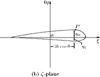
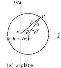
For transforming a circle to a cambered aerofoil, using Joukowski transformation, the center of the circle in the physical plane has to be shifted to a point in one of the quadrants. Let us consider the center in the first coordinate of z-plane, as shown in Figure 4.8(a).

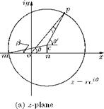
Figure 4.8 Transformation of a circle to a cambered aerofoil.


As seen in Figure 4.8(a):

• the center c of the circle is displaced horizontally as well as vertically from the origin, in the physical plane.

• let the horizontal shift of the center be “on = be" and

• the vertical shift be “cn = h"

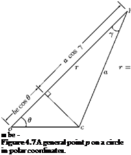
The point p on the circle and its distance from the origin can be represented as shown in Figure 4.9.

Both the vertical shift h and eccentricity e are small. Therefore, the angle в, subtended at point m, by om and cm is small, hence, cos в & 1, also cos у & 1. Therefore, the radius of the circle becomes:

a = (b + be) cos в = (b + be).
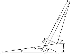
The vertical shift of the center can be expressed as:

h = a sin в = b (1 + е)в.

But e and в are small, therefore, h becomes:

h ^ Ьв

By dropping perpendiculars on to op, from n and c, it can be shown that: op = r = a cos у + h sin в + be cos в.

The angle y is small, therefore, cos y ^ 1, thus:

r = a + h sin в + be cos в. Substituting for a = (b + be) and h = Ьв, r becomes:

r = b + be + bв sin в + be cos в.

This can be expressed as:

Подпись: (4.7a)r

– = 1 + e + e cos в + в sin в b

or

– = [1 + (e + e cos в + в sin в)]

Expanding and retaining only the first order terms, we have:

Подпись: (4.7b)– = 1 — e — e cos в — в sin в r

since e and в are small, their powers are assumed to be negligibly small. The Joukowski transformation function is:

b2

Z = Z + —.

z

Replacing z with r е’в, we have:

reie + – e-ie

r

rb

Substituting for — and – from Equations (4.7a) and (4.7b), we get: br

Z = 2b cos в + i2b(e + e cos в + в sin в) sin в

or

Z + in = 2b cos в + i2b(e + e cos в + в sin в) sin в.

Подпись: n =

Equating the real and imaginary parts, we get:

These coordinates represent a cambered aerofoil, in the Z-plane, as shown in Figure 4.8(b). Thus, the circle with center c in the first quadrant of z-plane is transformed to a cambered aerofoil section in the Z-plane, as shown in Figure 4.8(b), with coordinates Z and n, given by Equations (4.8a) and (4.8b). It is seen that:

• The chord of the cambered aerofoil is also 4b, as in the case of symmetrical aerofoil.

• When в = 0, that is, when there is no vertical shift for the center of the circle, in the physical plane, the transformation results in a symmetrical aerofoil in the transformed or Z-plane.

• The second term in the n expression, in Equation (4.8b), alters the shape of the aerofoil section, because it is always a positive addition to the n-coordinate (ordinate).

• The trailing edge is sharp (n = 0, at в = n), and the fmax is at the quarter chord point (Z = b).

Thickness to Chord Ratio of Symmetrical Aerofoil

The maximum thickness of the aerofoil occurs where dn/dd = 0. Therefore, differentiating

П = 2be(1 + cos в) sin в with respect to в, and equating to zero, we get:

— = 2be(1 + cos в) cos в — 2be sin в sin в = 0 d0 v ‘

cos2 в — sin2 в + cos в = 0 2 cos2 в + cos в — 1 = 0 (2 cos в — 1) (cos в + 1) = 0.

Thus, either:

(2 cos в — 1) = 0

Подпись: or
(cos в + 1) = 0.

From the above relation, we get the following conditions corresponding to the maximum and minimum thickness of the aerofoil:

• cos в = 1/2, giving в = n/3 = 60°, at the maximum thickness location.

• cos в = —1, giving в = n, at the minimum thickness location.

Therefore, the maximum thickness is at the chord location, given by:

n

9 = 2b cos — = b.

9 3

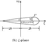
This point (b, 0), from the leading edge of the aerofoil, in Figure 4.6(b), is the quarter chord point. Thus, the maximum thickness tmax is at the quarter chord point. The maximum thickness tmax is given by 2ц, with в = n/3 in Equation (4.4b).

tmax = 2ц = 2x [2be(1 + cos в) sin в]

= 2x [2be(1 + cos 60°) sin 60°]

= 2 x 2be x (1 +—^ x.

I 2 2

Подпись: ^max Подпись: 3V3 be Подпись: (4.5)

That is:

Подпись: or Подпись: t c Подпись: (4.6)

Thus, the thickness to chord ratio of the aerofoil becomes:

From the above relation for maximum thickness and thickness-to-chord ratio, it is seen that the thickness is dictated by the shift of the center of the circle or eccentricity e. The eccentricity serves to fix the fineness ratio (t/c ratio) of the profile. For example, a 20% thick aerofoil section would require an eccentricity of:

e = 0.2/1.3 = 0.154.

Thus, at the trailing edge, both upper and lower surface are tangential to the f-axis, and therefore, to each other. In other words, the trailing edge is cusped. This kind of trailing edge would ensure that the flow will leave the trailing edge without separation. But this is possible only when the trailing edge is cusped with zero thickness. Thus, this is only a mathematical model. For actual aerofoils, the trailing edge will have a finite thickness, and hence, there is bound to be some separation, even for the thinnest possible trailing edge.

Note: Transformation of a circle with its center at a distance be on the negative side of the x-axis, in the physical plane, will result in a symmetrical aerofoil, with its leading edge on the negative side of the f-axis (mirror image of the aerofoil profile about the n-axis, in Figure 4.6), in the transformed plane. Similarly, positioning the center of the circle, with an offset, on the у-axis, will get transformed to a symmetrical aerofoil, with its leading and trailing edges on the n-axis, in the transformed plane.

Transformation of Circle to Symmetrical Aerofoil

To transform a circle into a symmetrical aerofoil, the center of the circle in the z-plane should be shifted from the origin and located slightly downstream of the origin, on the x-axis, as shown in Figure 4.6(a). This shift would cause asymmetry to the profile (about the ordinates of the transformed plane) of the transformed shape obtained with the Kutta— Joukowski transformation function.

Подпись: c Подпись: b2 z + — z_

Let the horizontal shift of the center of the circle c, from the origin o, also called as the eccentricity to be e. The actual distance of the center of the circle from the origin is be, as shown in Figure 4.6(a). Thus,

be cos в + a cos у

Подпись: ■ be - Figure 4.7 A general point p on a circle in polar coordinates. the radius of the circle is (b + be). Let us represent the general point p on the circle, in polar coordinates, as shown in Figure 4.7.

The distance of point p from the origin, shown in Figure 4.7, is:

op = r = be cos 9 + a cos у

where e and у are small. Therefore, the above distance r simplifies to:

r = be cos 9 + a

Substituting a = (b + be), we get:

r = be cos 9 + b + be = b(l + e + e cos 9).

This can be arranged as:

b

– = [1 + e (1 + cos 9)]-1. r

Подпись: - = 1 — e — e cos 9 r

But the eccentricity e is very small. Therefore, the term e (1 + cos 9) is very small compared to 1. Thus, expanding the right-hand-side of the above equation and retaining up to the first order terms, we get:

Thus, r and b can be expressed in terms of the horizontal shift e of the circle being transformed.

The transformation function can be expressed, in terms of r and в, by replacing z with re’B, as:

b2

Z = Z + — z

b2

= reie + – e-w

r

в + i sin в) +

b2

(cos в

– i sin в)

О

о

сл

r

r

b

r

b

+— cos в +

ib

– —

– sin в

u

r

u

r

= 2b cos в + i 2be(1 + cos в) sin в.

But:

Z = Z + in

Therefore:

Z + in = 2b cos в + i 2be(1 + cos в) sin в.

Подпись: Z =
Подпись: n=

Equating the real and imaginary parts, we get the coordinates of the transformed profile as:

These are the coordinates of a symmetrical aerofoil profile. Plot of Z and n for в from 0 to n and n to 2n gives a symmetrical profile shown in Figure 4.6(b). The chord (the shortest distance from the leading edge to the trailing edge) of the aerofoil is 4b.

Transformation of Circle to Ellipse

For transforming a circle to an ellipse using the Kutta-Joukowski transformation function:

b2

Z = Z + — z

the circle should have its center at the origin in the z-plane, but the radius of the circle should be greater than the constant b, in the above transformation function, that is, a > b.

Подпись: § n Подпись: b2 a + — a b2 a a

With the radius of the circle r = a, we can express the § and n expressions in Equation (4.1) as:

Eliminating в in the § and n expressions above, we get:

(4.3)

This is an ellipse with its major and minor axes, respectively, along the § and n axes in the Z-plane, as shown in Figure 4.5(b).

The major and minor axes of the ellipse, given by Equation (4.3), are The chord or the major axis of the ellipse = Maximum thickness or the minor axis of the ellipse =

Подпись: the following:Подпись: 2| a + ^ a 21 b2 2 I a a The fineness ratio of the ellipse, defined as the ratio of the chord to maximum thickness, becomes:

Chord

Fineness ratio = ————————–

Maximum thickness

b2

a + —

_ _____ a_

= b2

a—-

a

a2 + b2 a2 — b2

Подпись: Fineness ratio Подпись: (a/b + b/a) (a/b — b/a) Подпись: (4.3a)

or

From this relation it is evident that for every value of the ratio a/b a new ellipse can be obtained.

Kutta-Joukowski Transformation

Kutta—Joukowski transformation is the simplest of all transformations developed for generating aerofoil shaped contours. Kutta used this transformation to study circular-arc wing sections, while Joukowski showed how this transformation could be extended to produce wing sections with thickness t as well as camber. In our discussions here, we make another simplification that the transformation is confined to the study of the actual contour of the circle, and to show how its shape changes on transformation.

In our discussion on Kutta—Joukowski transformation, it is important to note the following.

• The circle considered, in the physical plane, is a specific streamline. Essentially the circle is the stagnation streamline of the flow in the original plane 1 (z-plane).

• The transformation can be applied to the circle and all other streamlines, around the circle, to generate the aerofoil and the corresponding streamlines in plane 2 (f-plane) or the transformed plane. That is, the transformation can result in the desired aerofoil shape and the streamlines of the flow around the aerofoil.

It is convenient to use polar coordinates in the z-plane and Cartesian coordinates in f-plane. The Kutta—Joukowski transformation function is.

where b is a constant.

These § and n represent a straight line coinciding with the §-axis in the f-plane. The transformed line is thus confined to §-axis, as shown in Figure 4.4(b), and as в varies from 0 to n, point P moves from +2a to -2a. Thus, the chord of the locus of point P is 4a.

Note that the singularities at z = ± b produce sharp edges at Z = ± 2a. That is, the extremities of the straight line are sharp.

Examples of Simple Transformation

The main use of conformal transformation in aerodynamics is to transform a complicated flow field into a simpler one, which is amenable to simpler mathematical treatment. The main problem associated with this transformation is finding the best transformation function (formula) to perform the required operation. Even though a large number of mathematical functions can be envisaged for a specific transfor­mation, in our discussions here, only the well established transformations, which are commonly used in aerodynamics, will be considered. One such transformation, which generates a family of aerofoil shaped curves, along with their associated flow patterns, by applying a certain transformation to consolidate the theory presented in the previous sections, is the Kutta—Joukowski transformation.

Example 4.3

Transform the uniform flow parallel to x-axis of the physical plane, with the transformation function

Z = z2.

Solution

Expressing the transformation function Z = z2, in terms of x and y, we have the following:

Z = z2 = (x + iy)2 = x2 — y2 + 2xiy.

§ + in = X — y2 + i 2xy.

Equating the real and imaginary parts, we get the coordinates § and n, in the transformed plane, as:

22 § = x — y

П = 2xy.

The stream function for uniform flow parallel to x-axis, in the physical plane, is:

f = Vxy.

Therefore:

f

Подпись: =y.

Let f = k.
Vx

Also:

Подпись: xПодпись: But f = § + in- Thus:
2y

Therefore, § becomes:

t – П 2 § 4y2 y.

Replacing y with k, we get:

§ = — k2

4k2

or:

П = 2k/ § + k2.

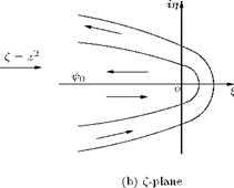
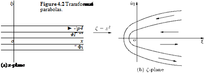
For a constant value of k, this gives a parabola. Therefore, horizontal streamlines, shown in Figure 4.2(a), in the z-plane, transform to parabolas in the f-plane, as shown in Figure 4.2(b). Thus, applying the transformation function f = z2 to an uniform flow parallel to x-axis in the physical plane, we get parabolas in the f-plane.

Note that the flow zones above or below x-axis, in the z-plane, transform to occupy the whole of the f-plane. These zones of the z-plane must be treated separately. In this case, the streamlines in the lower part of the z-plane, extending along the negative y-direction, will be taken with the flow streaming from left to right, in Figure 4.2(b). The streamlines for this flow is given by:

f = Vxy,

where y is always negative. Thus, the stream function is negative in this zone.

Example 4.4

Find the transformation of the uniform flow parallel to the y-axis, in the z-plane, using the transformation function Z = z2.

Solution

The given flow field is as shown in Figure 4.3(a).

For the transformation function Z = z2, from Example 4.3, we have:

22 Z = x – y

П = 2xy.

The stream function for the downward uniform flow, parallel to y-axis, shown in Figure 4.3(a), is:

ф = VyX.

Подпись: xiy■

o

(a) z-plane

Thus, for a given ф and Vy.

ф

x = — = constant. Vy

Let x = — = k.

Vy

Подпись: 2

The coordinates § and n can be arranged as follows.

П = 2x fxJ-—§.

Подпись: П = 2ky/k2 — § .

Replacing x with k, we get.

For different values of k this represents a set of parabolas, as shown in Figure 4.3(b).

By Analytical Means

For a given flow pattern in the physical plane, each streamline of the flow can be represented by a separate stream function. Transferring these stream functions, using the transformation function, Z = f (z), the corresponding streamlines in the transformed plane can be obtained. For example, the streamlines in the physical plane given by the stream function:

^ = f (x, y) = constant

can be expanded, using the transformation function:

Z = f (z),

where z = x + iy, to obtain the following three equations:

Z = constant = f (x, iy)

= f1(x, y) + if2(x, y).

But f = § + in, therefore:

§ + in = fi(x, y) + if2(x, y).

Comparing the real and imaginary parts, we have:

§ = f1 (x, y) n = h{x, y).

From these equations, § and n can be isolated, by eliminating x and y. The resulting expressions for § and n will represent the transformed line in the f-plane.

Example 4.2

Transform the straight lines, parallel to the x-axis in the physical plane, with the transformation function f = 1/z.

Solution

From the transformation function f = /z, we have:

1

Z = –

z

_ 1

x + iy

Multiplying and dividing the numerator and denominator of the right-hand side by (x — iy), we get:

x iy

f = ——————–

(x + iy)(x — iy)

x — iy

x2 + y2

x iy

x2 + y2 x2 + y2

But

Z = § + in.

Therefore:

t,-= у

^ x2 + y2 x2 + y2

Transformation of Flow Pattern

4.1 Introduction

Any flow pattern can be considered to consist of a set of streamlines and potential lines (ф and ф lines). Thus, transformation of a flow pattern essentially amounts to the transformation of a set of streamlines and potential lines, whilst the transformation of individual lines implies the transformation of a number of points.

4.2 Methods for Performing Transformation

Choose a transformation function Z = f (z) to transform the points specified by the Cartesian coordinates x and y, in the physical plane, given by z = x + iy, to a transformed plane given by Z = Z + in. To carry out this transformation, we need to expand the transformation function Z = f (z) = Z + in, equate the real and imaginary parts and find the functional form of Z and n, in terms of x and y, that is, find:

Z = f1 (x, y) n = f2(x, y).

Thus, any point p(x, iy) in the physical plane (z-plane) gets transformed to point P(Z, in) in the trans­formed plane (Z-plane).

Example 4.1

Transform a point p(x, iy) in the physical plane to Z-plane, with the transformation function Z = 1/z.

Solution

Given, Z = 1/z. Also, z = x + iy.

Theoretical Aerodynamics, First Edition. Ethirajan Rathakrishnan.

© 2013 John Wiley & Sons Singapore Pte. Ltd. Published 2013by John Wiley & Sons Singapore Pte. Ltd.

Therefore, from the transformation function Z = 1/z, we get:

Using these expressions for § and n, any point in the physical plane, with coordinates (x, y), can be transformed to a point, with coordinates (§, n), in the transformed plane. That is, from any point of the given flow pattern in the original plane, values of the coordinates x and y can be substituted into the expressions of § and n to get the corresponding point (§, n), in the transformed plane.