Our heavyweight helicopter equal in the world does not have
In Rostov started production of the most load-lifting rotary-wing car The Russian holding «Helicopt[...]

Everything about aircrafts and helicopters. News and events in aviation worldwide. Civil, transportation, military helicopters and airplanes.

Everything about aircrafts and helicopters. News and events in aviation worldwide. Civil, transportation, military helicopters and airplanes.

Everything about aircrafts and helicopters. News and events in aviation worldwide. Civil, transportation, military helicopters and airplanes.

Everything about aircrafts and helicopters. News and events in aviation worldwide. Civil, transportation, military helicopters and airplanes.


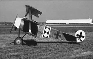
A triplane is a fixed-wing aircraft equipped with three vertically-stacked wing planes. Tailplanes and canard fore-planes are not normally included in this count, although they may occasionally be. A typical example for triplane is the Fokker Dr. I of World War I, shown in Figure 1.7.
|
Figure 1.7 Fokker Dr. I of World War I. |
The triplane arrangement may be compared with the biplane in a number of ways. A triplane arrangement has a narrower wing chord than a biplane of similar span and area. This gives each wing plane a slender appearance with a higher aspect ratio, making it more efficient and giving increased lift. This potentially offers a faster rate of climb and tighter turning radius, both of which are important in a fighter plane. The Sopwith Triplane was a successful example, having the same wing span as the equivalent biplane, the Sopwith Pup.
Alternatively, a triplane has a reduced span compared with a biplane of given wing area and aspect ratio, leading to a more compact and lightweight structure. This potentially offers better maneuverability for a fighter plane, and higher load capacity with more practical ground handling for a large aircraft type.
The famous Fokker Dr. I triplane was a balance between the two approaches, having moderately shorter span and moderately higher aspect ratio than the equivalent biplane, the Fokker D. VI.
Yet a third comparison may be made between a biplane and triplane having the same wing planform— the triplane’s third wing provides increased wing area, giving much increased lift. The extra weight is partially offset by the increased depth of the overall structure, allowing a more efficient construction. The Caproni Ca.4 series had some success with this approach.
These advantages are offset, to a greater or lesser extent in any given design, by the extra weight and drag of the structural bracing, and the aerodynamic inefficiency inherent in the stacked wing layout. As biplane design advanced, it became clear that the disadvantages of the triplane outweighed the advantages.
Typically the lower set of wings are approximately level with the underside of the aircraft’s fuselage, the middle set level with the top of the fuselage, and the top set supported above the fuselage on cabane struts.
Aircraft built with two main wings (or three in a triplane) can usually lift up to 20% more than can a similarly sized monoplane of similar wingspan. Biplanes will therefore typically have a shorter wingspan than a similar monoplane, which tends to afford greater maneuverability. The struts and wire bracing of a typical biplane form a box girder that permits a light but very strong wing structure.
On the other hand, there are many disadvantages to the configuration. Each wing negatively interferes with the aerodynamics of the other. For a given wing area the biplane generates more drag and produces less lift than a monoplane.
Now, one may ask what is the specific difference between a biplane and monoplane? The answer is as follows.
A biplane has two (bi) sets of wings, and a monoplane has one (mono) set of wings. The two sets of wings on a biplane add lift, and also drag, allowing it to fly slower. The one set of wings on a monoplane do not add as much lift or drag, making it fly faster, and as a result, all fast planes are monoplanes, and most planes these days are monoplanes.
A biplane is a fixed-wing aircraft with two superimposed main wings. The Wright brothers’ Wright Flyer used a biplane design, as did most aircraft in the early years of aviation. While a biplane wing structure has a structural advantage, it generates more drag than a similar monoplane wing. Improved structural techniques and materials and the quest for greater speed made the biplane configuration obsolete for most purposes by the late 1930s.
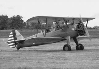
In a biplane aircraft, two wings are placed one above the other, as in the Boeing Stearman E75 (PT-13D) biplane of 1944 shown in Figure 1.6. Both wings provide part of the lift, although they are not able to produce twice as much lift as a single wing of similar size and shape because both the upper and lower wings are working on nearly the same portion of the atmosphere. For example, in a wing of aspect ratio 6, and a wing separation distance of one chord length, the biplane configuration can produce about 20% more lift than a single wing of the same planform.
|
Figure 1.6 Boeing Stearman E75 (PT-13D) biplane of 1944. |
In the biplane configuration, the lower wing is usually attached to the fuselage, while the upper wing is raised above the fuselage with an arrangement of cabane struts, although other arrangements have been used. Almost all biplanes also have a third horizontal surface, the tailplane, to control the pitch, or angle of attack of the aircraft (although there have been a few exceptions). Either or both of the main wings can support flaps or ailerons to assist lateral rotation and speed control; usually the ailerons are mounted on the upper wing, and flaps (if used) on the lower wing. Often there is bracing between the upper and lower wings, in the form of wires (tension members) and slender inter-plane struts (compression members) positioned symmetrically on either side of the fuselage.
A monoplane is a fixed-wing aircraft with one main set of wing surfaces, in contrast to a biplane or triplane. Since the late 1930s it has been the most common form for a fixed wing aircraft.
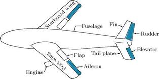
The main features of a monoplane aircraft are shown in Figure 1.3. The main lifting system consists of two wings, the port (left) and starboard (right) wings, which together constitute the aerofoil. The tail plane also exerts lift. According to the design, the aerofoil may or may not be interrupted by the fuselage. The designer subsequently allow for the effect of the fuselage as a perturbation (a French word which means disturbance) of the properties of the aerofoil. For the present discussion, let us ignore the fuselage, and treat the wing (aerofoil) as one continuous surface.
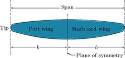
The ailerons on the right and left wings, the elevators on the horizontal tail, and the rudder on the vertical tail, shown in Figure 1.3, are control surfaces. When the ailerons and rudder are in their neutral positions, the aircraft has a median plane of symmetry which divides the whole aircraft into two parts, each of which is the optical image of the other in this plane, considered as a mirror. The wings are then the portions of the aerofoil on either side of the plane of symmetry, as shown in Figure 1.4.
 |
|
 |
|
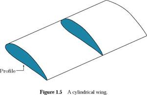
The wing tips consist of those points of the wings, which are at the farthest distance from the plane of symmetry, as illustrated in Figure 1.4. Thus, the wing tips can be a point or a line or an area, according to the design of the aerofoil. The distance between the wing tips is called the span. The section of a wing by a plane parallel to the plane of symmetry is called a profile. The shape and general orientation of the profile will usually depend on its distance from the plane of symmetry. In the case of a cylindrical wing, shown in Figure 1.5, the profiles are the same at every location along the span.
|
|
|
Figure 1.4 Typical geometry of an aircraft wing.
|
1.1.1 Types of Monoplane
The main distinction between types of monoplane is where the wings attach to the fuselage:
Low-wing, the wing lower surface is level with (or below) the bottom of the fuselage.
Mid-wing, the wing is mounted mid-way up the fuselage.
High-wing, the wing upper surface is level with or above the top of the fuselage.
Shoulder wing, the wing is mounted above the fuselage middle.
Parasol-wing, the wing is located above the fuselage and is not directly connected to it, structural support being typically provided by a system of struts, and, especially in the case of older aircraft, wire bracing.
The aerodynamic force Fad can be resolved into two component forces, one at right angles to V and the other opposite to V, as shown in Figure 1.1. The force component normal to V is called lift L and the
Theoretical Aerodynamics, First Edition. Ethirajan Rathakrishnan.
© 2013 John Wiley & Sons Singapore Pte. Ltd. Published 2013 by John Wiley & Sons Singapore Pte. Ltd.
component opposite to V is called drag D. If в is the angle between L and Fad, we have:
![]()
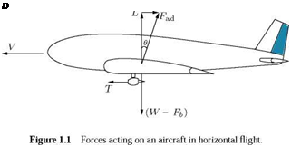 |
Fad cos в
Fad sin в D
T’
The angle в is called the glide angle. For keeping the drag at low value, the gliding angle has to be small. An aircraft with a small gliding angle is said to be streamlined.
At this stage, it is essential to realize that the lift and drag are related to vertical and horizontal directions. To fix this idea, the lift and drag are formally defined as follows:
“Lift is the component of the aerodynamic force perpendicular to the direction of motion."
“Drag is the component of the aerodynamic force opposite to the direction of motion."
Note: It is important to understand the physical meaning of the statement, “an aircraft with a small gliding angle в is said to be streamlined.” This explicitly implies that when в is large the aircraft can not be regarded as a streamlined body. This may make us wonder about the nature of the aircraft geometry, whether it is streamlined or bluff. In our basic courses, we learned that all high-speed vehicles are streamlined bodies. According to this concept, an aircraft should be a streamlined body. But at large в it can not be declared as a streamlined body. What is the genesis for this drastic conflict? These doubts will be cleared if we get the correct meaning of the bluff and streamlined geometries. In fluid dynamics, we learn that:
“a streamlined body is that for which the skin friction drag accounts for the major portion of the total drag, and the wake drag is very small."
“A bluff body is that for which the wake drag accounts for the major portion of the total drag, and the skin friction drag is insignificant."
Therefore, the basis for declaring a body as streamlined or bluff is the relative magnitudes of skin friction and wake drag components and not just the geometry of the body shape alone. Indeed, sometimes the shape of the body can be misleading in this issue. For instance, a thin flat plate kept parallel to the flow, as shown is Figure 1.2(a), is a perfectly streamlined body, but the same plate kept normal to the flow, as shown is Figure 1.2(b), is a typical bluff body. This clearly demonstrates that the streamlined and bluff nature of a body is dictated by the combined effect of the body geometry and its orientation to the flow direction. Therefore, even though an aircraft is usually regarded as a streamlined body, it can behave as a bluff body when the gliding angle в is large, causing the formation of large wake, leading to a large value of wake drag. That is why it is stated that, “for small values of gliding angle в an aircraft is said
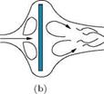 |
Figure 1.2 A flat plate (a) parallel to the flow, (b) normal to the flow.
to be streamlined.” Also, it is essential to realize that all commercial aircraft are usually operated with small gliding angle in most portion of their mission and hence are referred to as streamlined bodies. All fighter aircraft, on the other hand, are designed for maneuvers such as free fall, pull out and pull up, during which they behave as bluff bodies.
Example 1.1
An aircraft of mass 1500 kg is in steady level flight. If the wing incidence with respect to the freestream flow is 3°, determine the lift to drag ratio of the aircraft.
Solution
Given, m = 1500 kg and в = 3°.
In level flight the weight of the aircraft is supported by the lift. Therefore, the lift is:
L = W = mg = 1500 x 9.81 = 14715 N.
The relation between the aerodynamic force, Fad, and lift, L, is:
L = Fad cos в.
The aerodynamic force becomes:
L
Fad =
cos в _ 14715 cos 3°
= 14735.2 N.
The relation between the aerodynamic force, Fad, and drag, D, is:
D = Fad sin в.
Therefore, the drag becomes:
L 14715
![]() D
D
Note: The lift to drag ratio L/D is termed aerodynamic efficiency.
Ethirajan Rathakrishnan is Professor of Aerospace Engineering at the Indian Institute of Technology Kanpur, India. He is well-known internationally for his research in the area of high-speed jets. The limit for the passive control of jets, called Rathakrishnan Limit, is his contribution to the field of jet research, and the concept of breathing blunt nose (BBN), which reduces the positive pressure at the nose and increases the low-pressure at the base simultaneously, is his contribution to drag reduction at hypersonic speeds. He has published a large number of research articles in many reputed international journals. He is a fellow of many professional societies, including the Royal Aeronautical Society. Professor Rathakrishnan serves as editor-in-chief of the International Review of Aerospace Engineering (IREASE) Journal. He has authored nine other books: Gas Dynamics, 4th ed. (PHI Learning, New Delhi, 2012); Fundamentals of Engineering Thermodynamics, 2nd ed. (PHI Learning, New Delhi, 2005); Fluid Mechanics: An Introduction, 3rd ed. (PHI Learning, New Delhi, 2012); Gas Tables, 3rd ed. (Universities Press, Hyderabad, India, 2012); Instrumentation, Measurements, and Experiments in Fluids (CRC Press, Taylor & Francis Group, Boca Raton, USA, 2007); Theory of Compressible Flows (Maruzen Co., Ltd., Tokyo, Japan, 2008); Gas Dynamics Work Book (Praise Worthy Prize, Napoli, Italy, 2010); Applied Gas Dynamics (John Wiley, New Jersey, USA, 2010); and Elements of Heat Transfer, (CRC Press, Taylor & Francis Group, Boca Raton, USA, 2012).
This book has been developed to serve as a text for theoretical aerodynamics at the introductory level for both undergraduate courses and for an advanced course at graduate level. The basic aim of this book is to provide a complete text covering both the basic and applied aspects of aerodynamic theory for students, engineers, and applied physicists. The philosophy followed in this book is that the subject of aerodynamic theory is covered by combining the theoretical analysis, physical features and application aspects.
The fundamentals of fluid dynamics and gas dynamics are covered as it is treated at the undergraduate level. The essence of fluid mechanics, conformal transformation and vortex theory, being the basics for the subject of theoretical aerodynamics, are given in separate chapters. A considerable number of solved examples are given in these chapters to fix the concepts introduced and a large number of exercise problems along with answers are listed at the end of these chapters to test the understanding of the material studied.
To make readers comfortable with the basic features of aircraft geometry and its flight, vital parts of aircraft and the preliminary aspects of its flight are discussed in the first and final chapters. The entire spectrum of theoretical aerodynamics is presented in this book, with necessary explanations on every aspect. The material covered in this book is so designed that any beginner can follow it comfortably. The topics covered are broad based, starting from the basic principles and progressing towards the physics of the flow which governs the flow process.
The book is organized in a logical manner and the topics are discussed in a systematic way. First, the basic aspects of the fluid flow and vortices are reviewed in order to establish a firm basis for the subject of aerodynamic theory. Following this, conformal transformation of flows is introduced with the elementary aspects and then gradually proceeding to the vital aspects and application of Joukowski transformation which transforms a circle in the physical plane to lift generating profiles such as symmetrical aerofoil, circular arc and cambered aerofoil in the tranformed plane. Following the transformation, vortex generation and its effect on lift and drag are discussed in depth. The chapter on thin aerofoil theory discusses the performance of aerofoils, highlighting the application and limitations of the thin aerofoils. The chapter on panel methods presents the source and vortex panel techniques meant for solving the flow around nonlifting and lifting bodies, respectively.
The chapter on finite wing theory presents the performance of wings of finite aspect ratio, where the horseshoe vortex, made up of the bound vortex and tip vortices, plays a dominant role. The procedure for calculating the lift, drag and pitching moment for symmetrical and cambered profiles is discussed in detail. The consequence of the velocity induced by the vortex system is presented in detail, along with solved examples at appropriate places.
The chapter on compressible flows covers the basics and application aspects in detail for both subsonic and supersonic regimes of the flow. The similarity consideration covering the Parandtl-Glauert I and II rules and Gothert rule are presented in detail. The basic governing equation and its simplification with small perturbation assumption is covered systematically. Shocks and expansion waves and their influence on the flow field are discussed in depth. Following this the shock-expansion theory and thin aerofoil theory and their application to calculate the lift and drag are presented.
In the final chapter, some basic flights are introduced briefly, covering the level flight, gliding and climbing modes of flight. A brief coverage of phugoid motion is also presented.
The selected references given at the end are, it is hoped, a useful guide for further study of the voluminous subject.
This book is the outgrowth of lectures presented over a number of years, both at undergraduate and graduate level. The student, or reader, is assumed to have a background in the basic courses of fluid mechanics. Advanced undergraduate students should be able to handle the subject material comfortably. Sufficient details have been included so that the text can be used for self study. Thus, the book can be useful for scientists and engineers working in the field of aerodynamics in industries and research laboratories.
My sincere thanks to my undergraduate and graduate students in India and abroad, who are directly and indirectly responsible for the development of this book.
I would like to express my sincere thanks to Yasumasa Watanabe, doctoral student of Aerospace Engineering, the University of Tokyo, Japan, for his help in making some solved examples along with computer codes. I thank Shashank Khurana, doctoral student of Aerospace Engineering, the University of Tokyo, Japan, for critically checking the manuscript of this book. Indeed, incorporation of the suggestions given by Shashank greatly enhanced the clarity of manuscript of this book. I thank my doctoral students Mrinal Kaushik and Arun Kumar, for checking the manuscript and the solutions manual, and for giving some useful suggestions.
For instructors only, a companion Solutions Manual is available from John Wiley and contains typed solutions to all the end-of-chapter problems can be found at www. wiley. com/go/rathakrishnan. The financial support extended by the Continuing Education Centre of the Indian Institute of Technology Kanpur, for the preparation of the manuscript is gratefully acknowledged.
Ethirajan Rathakrishnan
1.1 Introduction
Aerodynamics is the science concerned with the motion of air and bodies moving through air. In other words, aerodynamics is a branch of dynamics concerned with the study of motion of air, particularly when it interacts with a moving object. The forces acting on bodies moving through the air are termed aerodynamic forces. Air is a fluid, and in accordance with Archimedes principle, an aircraft will be buoyed up by a force equal to the weight of air displaced by it. The buoyancy force Fb will act vertically upwards. The weight W of the aircraft is a force which acts vertically downwards; thus the magnitude of the net force acting on an aircraft, even when it is not moving, is (W — Fb). The force (W — Fb) will act irrespective of whether the aircraft is at rest or in motion.
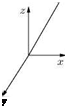
Now, let us consider an aircraft flying with constant speed V through still air, as shown in Figure 1.1, that is, any motion of air is solely due to the motion of the aircraft. Let this motion of the aircraft is maintained by a tractive force T exerted by the engines.
Newton’s first law of motion asserts that the resultant force acting on the aircraft must be zero, when it is at a steady flight (unaccelerated motion). Therefore, there must be an additional force Fa(j, say, such that the vectorial sum of the forces acting on the aircraft is:
Force Fad is called the aerodynamic force exerted on the aircraft. In this definition of aerodynamic force, the aircraft is considered to be moving with constant velocity V in stagnant air. Instead, we may imagine that the aircraft is at rest with the air streaming past it. In this case, the air velocity over the aircraft will be — V. It is important to note that the aerodynamic force is theoretically the same in both cases; therefore we may adopt whichever point of view is convenient for us. In the measurement of forces on an aircraft using wind tunnels, this principle is adopted, that is, the aircraft model is fixed in the wind tunnel test-section and the air is made to flow over the model. In our discussions we shall always refer to the direction of V as the direction of aircraft motion, and the direction of — V as the direction of airstream or relative wind.