Category Theoretical and Applied Aerodynamics

Linearization of the Pressure Coefficient

Linearization of the Pressure Coefficient

This is the last element of the theory that needs to be linearized. Using Cartesian coordinates, the exact Cp can be expanded as

Подпись: (3.24)Cp = -2 —

p U

This expression allows for the superposition of solutions as will be needed later.

Note that the pressure coefficient only dependent on u.

Figure3.6 depicts the situation for the small perturbation analysis: a thin airfoil will disturb the uniform flow only slightly, so that, the velocity vector V in the domain surrounding the profile (with the exception of singular points) will point inside a small ball centered at the end of the undisturbed velocity vector U. The

Подпись: Fig. 3.6 Effect of a small perturbation (u, w) on the orientation and modulus of V Linearization of the Pressure Coefficient

direction of the velocity vector is controlled primarily by w (tangency condition), whereas the magnitude of the vector is controlled primarily by u (pressure).

Note also, that stagnation will correspond to a point located near point Q, which implies large negative values of u. In fact, the theory will allow u to go to —to at a stagnation point.

Linearization of the Tangency Condition

The tangency condition reads V. nobstacie = 0. Consider a small element of the profile surface (dx, dz) = tdl where t is the tangent unit vector and dl the length of the element. A normal vector to the profile is ndl = (dz, – dx). The above condition can be written

(U + U, w). (dz, – dx)obstacle = ((U + u)dz – wdx) obstacle = 0 (3.18)

Dividing by dx (dx = 0) and applying the condition on the obstacle

Подпись:(U + u(x, z(x))) – w(x, z(x)) = 0

Using the fact that u, w, z and || are all of order O(d + c + a), the above expression can be simplified and expanded to first order as

dz dz d w d e 2

U – w(x, 0) + u(x, 0) – z(x) (x, 0) + O +- + a = 0 (3.20)

dx dx dz c c

Note that the third and fourth terms are already second order terms and can be included in the remainder. Finally, keeping only the leading terms results in the new form of the tangency condition

Подпись: (3.21)dz

w(x, 0) = U (x)

dx

To be more specific, one can formulate the tangency condition in terms of the profile shape and incidence as

Подпись: (3.22)w(x, 0±) = U (f ±(x) – a^

This operation is called the transfer of the tangency condition from the profile surface to the x-axis. Note that, as regard the mathematical treatment of the tangency condition, the profile is replaced by a slit along the x-axis with an upper (0+) and a lower (0-) edge.

Note also that the tangency condition is expressed only in terms of w.

Small Disturbance Linearization Method

As mentioned earlier, a unique solution exists for the inviscid, incompressible flow past an airfoil with sharp trailing edge. The solution satisfies the PDEs (2.1), the

Small Disturbance Linearization Method Подпись: (3.15)

tangency (2.4) and the asymptotic boundary conditions (2.6). It is of the general form

where the dependency on the geometrical parameters, coming from the tangency condition, is indicated. u and w are the exact perturbation velocity components and, in general, their analytical form cannot be obtained in closed form. However, since the solution depends continuously on the data, it is possible to expand u and w in a Taylor series with respect to the small parameters d, c and a. If we limit ourselves to the first order terms, we find

Подпись:Подпись:U

d e d e. .

Wd(x, z) + – we(x, z) + awa(x, z) + O +————— + a (3.16)

c c c c

where the terms O (d + ~c + a)2 represent the remainders in the Taylor expansions and are of second and higher order in the small parameters or products of them. They can be neglected if the parameters are small enough. Note that in the limit

de

a ^ 0 (3.17)

cc

the profile becomes a flat plate aligned with the incoming flow, and the uniform flow is recovered. This is the process we have used to derive the parametric representation of the Quasi-Joukowski profile geometry.

The governing equations are already linear. The next step is the linearization of the tangency condition.

Examples of Camber and Thickness Distributions

A symmetric profile has zero camber, i. e. d (x) = 0. The simplest camber distribution is the parabolic camber line:

Подпись: z Fig. 3.2 Rotation and shearing transformation

A cubic distribution can represent a small windmill if an axis is placed at the mid-chord x x x

d(x) = 6V3dX (1 – 2^1 – -) (3.8)

see the camber distributions in Fig. 3.3, where the z-coordinate has been stretched. A simple thickness distribution is represented by a semi-cubic

Подпись: e(x)Examples of Camber and Thickness Distributions(3.9)

which gives a finite trailing edge angle. The maximum thickness is at x = 3.

The Joukowski profile described in Sect. 2.5.1 can be linearized by expanding its analytic expression to first order in є and S, where (e, S) is related to the center of the cylinder image of the profile and also to thickness and camber. SeeFig.2.11. For є ^ 1 and S ^ 1, to first order the radius reads

r(ff) = —(є cos ff — S sin ff) + a ^1 + -) (3.10)

Substituting this into the Cartesian coordinates of the profile and expanding in terms of the small coefficients gives

Подпись:

Подпись: Fig. 3.3 Parabolic and cubic camber lines
Examples of Camber and Thickness Distributions

x(ff) = (a(1 + aa) — (- cos ff — S sin ff) + a(1

z(ff) = (a(1 + a) — (- cos ff — S sin ff) — a(1

which simplifies to give

x (ff) = 2a cos ff

z(ff) = 2є(1 — cos ff) sin ff + 2S sin2 ff

This is a parametric representation of a Quasi-Joukowski airfoil. In z(ff), the term proportional to є represents the thickness distribution and the term proportional to S, the camber. It is easy to see that the mean camber line is parabolic by elimination of ff in terms of x. The thickness distribution can also be expressed in terms of x as

Подпись: Fig. 3.4 Semi-cubic, Quasi-Joukowski and other thickness distributions Examples of Camber and Thickness Distributions
Подпись: Fig. 3.5 Quasi-Joukowski airfoil at incidence
Подпись: U

16 lx x 2

) = 3^75 eh (‘- c) t3J3)

The Quasi-Joukowski airfoil has a cusped trailing edge. The maximum thickness is at x = 4.

Подпись: e(x) Подпись: 216 25V5 Подпись: x 2 Подпись: (3.14)

The following thickness distribution has a maximum at x = | .As will be dis­cussed with viscous effects, having the maximum thickness far forward helps the boundary layer recovery as the flow slows down towards the trailing edge. This thickness distribution may be interesting for that reason:

See Fig. 3.4 for the different thickness distributions, where the scale has been stretched in the z-direction.

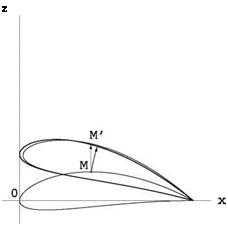
A Quasi-Joukowski airfoil at incidence, with the chord and camber lines is shown in Fig. 3.5.

Profile at Incidence

The thin profile is set at incidence a by performing a rotation of angle a in the clockwise direction, about the trailing edge. The exact transformation of a point M (x, z) of the profile into M’ (x’, z’) reads

Profile at IncidenceFig. 3.1 View of Wright Brothers glider (from NASA, http://wright. nasa. gov/ airplane/kiteQQ. html)

x’ = x + (x — c)(cos a — 1) + z sin a z’ = z — (x — c) sin a + z(cos a — 1)

Подпись: (3.4)In thin airfoil theory, we will further assume that the incidence angle (in radians) is small

(3.5)

With this assumption, the above transformation can be simplified to first order in d, c and a as

Подпись:(3.6)

which corresponds to a shearing transformation. This is a great simplification, because the equation of the profile is not modified by the transformation other than by the addition of a term proportional to a, since the ordinate of the profile at incidence now reads z±(x) = f ±(x) + a(c — x). SeeFig.3.2.

The question arises as to how small these coefficients have to be for the solution to be of practical use? In our experience, good results are obtained with relative cambers of the order of 6%, relative thicknesses of up to 12 % and angles of incidence between —10 and +10°. As will be seen, when a profile is used at its “design condition”, the viscous effects are minimized and the inviscid result will be representative of the real flow as far as the lift and moment coefficients are concerned. In off-design conditions, one should be more cautious with the bounds given above.

Inviscid, Incompressible Flow Past Thin Airfoils

Inviscid, Incompressible Flow Past Thin Airfoils

3.1 Introduction

The solution of the inviscid, incompressible and irrotational (potential) two-dimensional flow past an arbitrary profile with a sharp trailing edge exists and can be obtained using complex variables and mapping techniques. However, this approach is very difficult in general, except for particular classes of profiles, such as the Joukowski airfoils.

A more practical approach consists in simplifying the model one step further by assuming what is called a “thin airfoil”, an airfoil that creates only a small disturbance to the uniform incoming flow. It will then be possible to simplify the tangency con­dition, linearize the expression of the pressure coefficient and construct the solution of the flow past an arbitrary airfoil, using superposition of elementary solutions.

3.1.1 Definition of a Thin Airfoil

The thin airfoil geometry is defined with the profile chord aligned with the x-axis, from x = 0 to x = c, which corresponds to zero incidence. The (smooth) leading

© Springer Science+Business Media Dordrecht 2015 51

J. J. Chattot and M. M. Hafez, Theoretical and Applied Aerodynamics,

DOI 10.1007/978-94-017-9825-9_3

edge is tangent to the z-axis at the origin, as in Fig. 3.2. The sharp trailing edge is located at (c, 0).

The equations of the upper and lower surfaces of the airfoil are given by f + (x) and f -(x), respectively. The camber distribution d(x) and thickness distribution e(x) > 0 are defined as follows

d(x) = 2 (f + (x) + f -(x) , e(x) = f + (x) – f -(x) (3.1)

Note that, with the above definition of the airfoil geometry, f ±(0) = f ±(c) = 0. Hence, d(0) = e(0) = d(c) = e(c) = 0. With these distributions, the profile upper and lower surfaces are obtained from the superposition of camber and thickness as

11

f +(x) = d(x) + 2e(x), f (x) = d(x) – 2e(x) (3.2)

The curve z = d (x) is called the mean camber line. Let d be its maximum absolute value. The maximum value of e(x), e is called maximum thickness.

The relative camber of the airfoil is d and | is the relative thickness.

A thin airfoil is defined as an airfoil with small relative camber and relative thickness

de

– << 1, – << 1 (3.3)

cc

The Wright Brothers glider wings can be considered as equipped with thin airfoils as can be seen in Fig. 3.1.

Problems

2.10.1

A 2-D model for tornadoes can be described as a core cylinder of fluid with solid body rotation and a potential vortex flow outside the core. Plot the velocity distribution and streamlines. Plot the lines of constant potentials where they exist. What is Bernoulli’s law for such a flow? Calculate the pressure distribution and in particular the pressure at the center (Hint: use normal momentum equation to calculate the pressure in the core).

2.10.2

A 2-D model for hurricanes can be described by a potential vortex and a source for the flow outside the core. Show that the streamlines are spirals. Find the velocity and pressure distributions.

2.10.3

Derive the formula for velocity distributions due to a doublet using summation of velocity vectors of a sink and a source of strength Q and a distance 2a apart, in the limit of a ^ 0 and Q ^ro, such that aQ = D.

2.10.4

Show that the velocity due to a doublet with its axis in the x-direction is the derivative with respect to x of the velocity field due to a source.

2.10.5

Show that a doublet can be produced by a pair of counter rotating potential vortices of strength Г and —Г at a distance 2a, along the z-axis, in the limit a ^ 0 and Г ^ro, such that a Г is finite (Fig.2.30).

2.10.6

Show that the velocity due to a doublet with its axis in the x-direction is the derivative w. r.t. z of the velocity field due to a potential vortex.

2.10.7

Obtain the velocity and pressure distributions around a Rankine body described by the closed streamline due to a source and a sink of equal strength and at a distance 2a apart in a uniform stream.

2.10.8

Obtain the velocity and pressure distributions around a Kelvin body described by the closed streamline due to a pair of potential vortices of equal strength and opposite direction in a uniform stream, perpendicular to their axis.

2.10.9

Show that the Joukowski transformation with e = 8 = 0, maps a circle to a flat plate with c = 4a, hence for a flat plate at incidence produces a lift C; = 2n sin a. What is the drag coefficient Cd? Explain d’Alembert paradox, considering that the pressure acting normal to the flat plate will produce a force normal to the plate and not normal to the flow direction!

Problems

Fig. 2.30 Problem 2.10.10

2.10.10

Show that the Joukowskitransformation with e = 0and0 <8 ^ 1 maps a circle to a shallow circular arc as in Fig. 2.27. Find the pressure distribution over the circular arc and calculate C; and Cd. Where is the center of pressure? Where is the aerodynamic center?

2.10.11

Consider an ellipse at incidence. Show that the lift is zero. Consider next an ellipse with a small flap at the trailing edge. Find the lift (Hint: use Joukowski transformation).

Construct a symmetric airfoil with a blunt leading edge and a sharp trailing edge (Hint: use a parabola or a circle for the nose and a cubic or a quartic for the rest of the airfoil). Plot the airfoil shape.

Reference 1. White, F. M.: Fluid Mechanics, 7th edn. McGraw Hill, New York (2009)

Chapter 3

Summary of Chapter 2

In this Chapter, mathematical solutions are found analytically for a theoretical model of steady, two-dimensional, inviscid, incompressible, adiabatic flow with uniform upstream conditions. This flow has no vorticity. The governing first order partial dif­ferential equations (Cauchy/Riemann system) for the velocity components are linear, representing conservation of mass and the irrotationality condition. The pressure is decoupled and is obtained from Bernoulli’s law.

The Cauchy/Riemann system can be replaced by a single potential or stream – function equation which satisfies Laplace equation. The uniform flow is a trivial
solution of these equations. Other fundamental solutions are found (i. e. source/sink and potential vortex) and more general solutions are constructed via superposition, for example doublet and half-body flows.

The solution for the flow over a circular cylinder is of particular interest. The boundary conditions are the tangency condition at the solid surface and uniform flow in the far field. From symmetry, the cylinder has zero lift and zero drag. The latter result is referred to d’Alembert Paradox. In the real flow, there is drag due to friction and due to the difference in pressure on the front and the back of the cylinder because of separation. However, this mathematical solution is useful since it provides the pressure distributions over thin bodies at small angle of attack via mapping techniques. For example, the Joukowski transformation provides analytical solutions for a family of symmetric shapes. In such cases, the flow is attached and the viscous effects are confined to the thin boundary layers, hence the mathematical model of inviscid flow yields a reasonable approximation.

A more interesting case is the flow with lift. Flow asymmetry is necessary to generate lift. One can think of a rotating cylinder. In the real flow, the effect of the rotation of the cylinder is transmitted through a viscous layer, augmenting the velocity on one side and retarding it on the other, thus creating a circulatory flow and lift. The inviscid flow model however, admits a slip velocity at the surface and has no mechanism to control the asymmetry other than adding a small flap to force flow stagnation at a specified point on the surface of the cylinder. The mathematical solution is obtained as uniform flow plus a doublet and a potential vortex. The doublet strength is determined to satisfy the tangency condition at the cylinder surface. In general the mathematical solution is not realistic since there is flow separation (unless the cylinder rotates so fast that the boundary layer is confined to a thin annulus attached to the surface). Through the Joukowski transformation however, the solution can be mapped to a flow over a lifting airfoil. To obtain a solution consistent with the experimental results, at least for small angles of attack when the flow is attached and the viscous effects are confined to thin boundary layers, the circulation in the mathematical model is chosen such that the flow leaves the trailing edge smoothly, in a direction bisecting the trailing edge angle. This celebrated Kutta-Joukowski condition renders the mathematical solution unique by choosing the most physically relevant solution which has no flow around the trailing edge, since in a real flow, the viscous effects will not allow such a behavior.

Once the vortex strength is determined, the lift is calculated via the Kutta – Joukowski lift theorem which is based on momentum balance. The same result can be obtained by integrating the surface pressure.

The Kutta-Joukowski transformation has allowed us to obtain exact solutions for the flow past ellipses, flat plates and Joukowski airfoils. The circles in the cylinder plane and their images in the physical plane are shown for example in Fig. 2.29.

Finally, the main formulae in this chapter are the Kutta-Joukowski lift theorem result L’ = pUГ and the relation between the strength of the potential vortex and the position of the stagnation points on the cylinder. Through the Joukowski transformation, these formulae reveal the dependence of the lift on the angle of attack for a family of airfoils.

Summary of Chapter 2

Fig. 2.29 Circles 1,2 and 3 in the cylinder plane and their images: 1 ellipse, 2 flat plate, 3 Joukowski profile

In the next chapter, thin airfoil theory is introduced. The same results can be obtained numerically, using for example the method of singularities.

More accurate analyses, where the viscous effects in the boundary layer are fully accounted for, are presented later. Also, compressibility and three-dimensional effects are dealt with in separate chapters.

Joukowski Airfoil at Incidence

The same result for the potential function is obtained in this case with e > 0 and

8 > 0

, Г

Ф = 2Ua’ cos(0 – a) – (в – a) (2.106)

2n

where now a’2 = (a + e)2 + 82, with the following formula for the circulation that enforces the Kutta-Joukowski condition

Г = 4n U ((a + e) sin a + 8 cos a) (2.107)

and lift coefficient

Cl = 2n 1 +—sin a + cos a (2.108)

Joukowski Airfoil at Incidence Joukowski Airfoil at Incidence

The exact solution is quite complicated and is best calculated numerically. How­ever, assuming small values for thickness and camber, i. e. | ^ 1 and 8 ^ 1, the formula can be linearized to give the x-component of velocity as

This formula holds for all values of incidence, |a|< 2. For small values of a the small disturbance result is recovered. For example, for a = 8 = 0 and i = 0.077 corresponding to a 10 % thick symmetric Joukowski airfoil, the pressure coefficient at zero incidence is shown in Fig.2.28.

The thin airfoil solution is a straight line, since the perturbation velocity in x’ is linear

Подпись: (2.111)U+^’) = U(1 + 57! C (3 – 4 f))

To find the solution in the physical plane and in particular the surface velocity for arbitrary Joukowski airfoils, the values of the potential function at certain points on the circle, image of the profile, are first calculated. The same values are assigned to the corresponding points on the airfoil which can be found from the transformation formulae. The surface velocity can be evaluated numerically as

АФ

V = (2.112)

As

where АФ is the difference between the values of Ф at the two close points on the surface and As is the length of the airfoil segment between these two points. The surface pressure distribution is readily obtained from Bernoulli’s law, i. e.

Подпись: Cp = 1 -Joukowski Airfoil at Incidence

Joukowski Airfoil at Incidence

(2.113)

Circular Arc

For this case, e = 0 and 8 > 0. The polar coordinates are centered at (0, 8). The potential function reads

Подпись: (2.99)

Circular Arc

Ф = 2Ua’ cos(0 — a) — (в — a)

Circular Arc Подпись: (2.100)

where a’2 = a2 + 82. The azimuthal component of velocity on the cylinder is

The circulation, that places the stagnation point at (0, a) is

Г — 4n U (a sin a + 8 cos a) (2.101)

Circular Arc Подпись: (2.102)

and the lift coefficient as given by the Kutta-Joukowski lift theorem

The most interesting situation for this airfoil corresponds to a = 0 where a symmetry w. r.t. the z-axis (and Z-axis) is obtained. In this case, the surface velocity reduces to a simple expression

V _ a2 + 28 sin ву/a2 + (8 sin в)2 (2103)

— 2 2 (2.103)

U a2 + 82

The pressure coefficients are shown in Fig. 2.27 for a — 0, d — 0.1 and C — 0.2.

A consequence of symmetry is that the leading edge, as the trailing edge, satisfies a Kutta-Joukowski condition. This is only possible for a — 0. The leading edge is “adapted”. a — 0 is the ideal angle of attack for the circular arc. The lift coefficient in this case is Cl — 2n 8. The lift per unit span

Подпись: (2.104)L’ — 4npU 28 — 2npU 2d

(a) (b)

Подпись: Fig. 2.27 Cp distributions for the circular arc at a — 0 : a d — 0.1, b d — 0.2
Circular Arc

—Cp — Cp

only depends on d, where d = 28 represents the height of the circular arc in the physical plane (the chord is c = 4a). This result was first obtained by Kutta in 1902. The center of pressure is at the center of the arc, i. e.

(2.105)