Category AERODYNAMICS

Constant-Strength Doublet Method

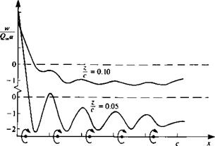
The simplest two-dimensional panel code that can calculate the flow over thick lifting airfoils is based on the constant-strength doublet. The surface pressure distribution computed by this method is satisfactory on the surface, but since this element is equivalent to two concentrated vortices at the edges of the element, near-field off-surface velocity computations will have the same fluctuations as shown in Fig. 11.11 (but the velocity calculated at the collocation point and the resulting pressure distribution are correct).

Selection of singularity element. Consider the constant-strength doublet ele­ment of Section 10.2.3 pointing in the positive z direction, where the panel is based on a flat element. To establish a normal-velocity boundary condition based method, the induced velocity formulas of Eqs. (10.29) and (10.30) are used (which are equivalent to two point vortices with a strength ц at the panel edges)

Подпись:= Г_________ £______________ z_

Up 2n L(x – Xj)2 + z2 (x-x2)2 + z2

-/*[ X~XA X~X2 1 .

2л l(x-xt)2 + z2 (x-x2)2 + z2 pane

Here, again, the velocity components (и, w)p are in the direction of the panel local coordinates, which need to be transformed back to the x-z system by Eq.

(11.23) .

This procedure can be included in an induced-velocity subroutine DUB2DC (where C stands for constant) that will compute the velocity (и, w) at an arbitrary point {x, z) due to the jth element:

Подпись: (11.32)(u, w) = DUB2DC x, z, xjt zjt xj+u zj+l)

Discretization of geometry. The panel corner points and collocation points are generated exactly as in the previous section (see Fig. 11.18). However, in this lifting case, a wake panel shown in Fig. 11.20 has to be specified. This doublet element will have a strength juw and extends to x = In practice, the far portion (starting vortex) of the wake will have no influence and can be placed far downstream [e. g., at (°°, 0)].
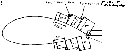
image435

Influence coefficients. To obtain the normal component of the velocity at a collocation point (e. g., the first point) due to the y’th doublet element, Eq.

(11.32)

image436

is used

The influence coefficients a, y are defined as the velocity components normal to the surface. Consequently, the contribution of a unit strength singularity element j, at collocation point 1, is

av = (и. w)y • “і

Similarly to the case of the constant-source method, the influence coefficients can be found by using Eq. (11.27):

image437(11.27)

where a-, and at are the first and the )th panel angles, as defined in Fig. 11.17, and (uv, wiy)p are the velocity components of Eqs. (11.30) and (11.31) due to a unit-strength element as measured in the panel frame of reference.

To evaluate the influence of the element on itself, at the center of the panel, Eqs. (10.32) and (10.33) are recalled

Подпись: up(x, 0±) = 0 (11.34)

(11.35)

Consequently, when і = j the influence coefficient becomes

Подпись:2

image439

where ДCj is the ith panel chord.

Establish boundary condition (RHS). The free-stream normal velocity com­ponent RHS, is found as in the previous examples (e. g., by using Eq. (11.6)).

Solve equations. Specifying the boundary condition of Eq. (11.4) for each (i = 1 —» N) of the collocation points results in a set of algebraic equations with the unknown fij (j = l-*N). However, observing the equivalent vortex representation in Fig. 11.20 reveals that the strength of the vortex at the trailing edge is Г = Mi – Hn – Recalling the Kutta condition that the circulation at the trailing edge is zero requires the addition of a wake panel that will cancel this vortex:

(м і AOv) + №w — 0 (11.36)

A combination of this equation with the N boundary conditions results in N + 1 linear equations:

a in «iw J

«2IV a2W | A*2 «AW °NW j

~ 1 1 / /zw/

Подпись: RHS^ RHS2 RHSnJ 0 Подпись:«п

«21

am

This system of equations is the numerical equivalent of the boundary condition (Eq. (11.4)) and is well defined and will have a stable solution.

Calculation of pressures and loads. Once the strength of the doublets /і/ is known, the perturbation tangential velocity component at each collocation point can be calculated by summing the induced velocities of all the panels, using Eq. (11.33). The tangential velocity at collocation point i is then

N+1

q,, = 2 (“. w)a • t, (11.37)

7 = 1

where (и, w)q is the result of Eq. (11.33) and t, is the local tangent vector defined by Eq. (11.3a) and the (N + l)th component is due to the wake. Note that to evaluate the tangential velocity component induced by a panel on itself Eq. (3.141) can be used:

1 du(l)

Я, = 2 ~дГ onPanel (11.38)

where l represents distance along a surface line. So when evaluating the tangential component of the perturbation velocity the result of Eq. (11.38) must be included (when і = j in Eq. (11.37)). The pressure coefficient can be computed by using Eq. (11.18):

Подпись:r = і + fr)/

Qi

image440

FIGURE 11.21

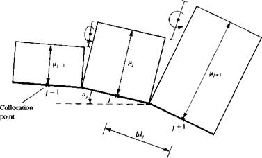
Typical segment of constant-strength doublet panels on the airfoil’s surface.

where

(<2J, = tyQ~ (11.39a)

Note that the local lift can be calculated, too, by using the Kutta Joukowski formula for a point vortex:

ALj = pQS, = —P0oo(/i,+i “ Py) (11.40)

where the minus sign is used for doublet panels pointing outside the airfoil. This formulation should be equivalent to the result that we get by assuming constant pressure on the panel,

ACtj = —CP/ Alj cos ос, (11.41)

where A lj and ay are shown in Fig. 11.21. The total lift and moment are obtained by integrating the contribution of each element:

L = 2>Ly (11.42)

i=і N

M„= 2 ALj(xj cos a) (11.43)

y=і

and the nondimensional coefficients can be calculated by using Eqs. (11.12) and (11.13).

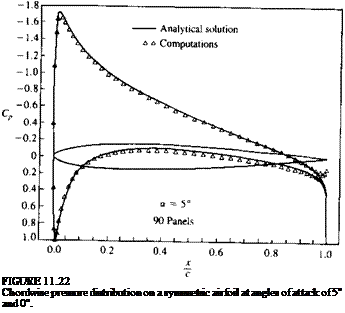
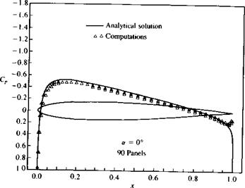
Example 1 Lifting thick airfoil. The above method was used for computing the pressure distribution over the airfoil of Section 6.6, as shown in Fig. 11.22. The data agrees satisfactorily with the analytic solution for both the zero (Fig. 11.22a) and five-degree angle-of-attack conditions (Fig. 11.226). A slight disagreement is

image441

c

Подпись: FIGURE 11.22 Chordwise pressure distribution on a symmetric airfoil at angles of attack of 5° and 0°.

visible near the maximum suction area and near the rear stagnation point. These results can be improved by moving the grid and the collocation points near these areas, but such an optimization procedure is not carried out here. The computer program used for this example is included in Appendix D (Program No. 3).

Constant-Strength Source Method

The constant-strength source methods that will be presented here are capable of calculating the pressures on a nonlifting thick airfoil and were among the first successful codes used.101 For explaining the method, we shall follow the basic six-step procedure:

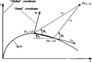
Selection of singularity element. Consider the constant-strength source ele­ment of Section 10.2.1, where the panel is based on a flat surface element. To establish a normal-velocity boundary condition based method, only the induced velocity formulas are used (Eqs. (10.17) and (10.18)). The parameters в and r are shown in Fig. 11.17 and the velocity components (n, w)p in the directions of the panel coordinate system are

Подпись:° і Гі

(11.20)

In terms of the panel jc-z variables these equations become

image430

FIGURE 11.17

Nomenclature for a planar surface panel.


w„ = ^- tan 1 — ———- tan 1 —-— panel coordinates (11.22)

2ж L x-x2 x—xti

Note that for simplicity, the subscript p was omitted in these equations since in general it is obvious that the panel coordinates must be used (however, when the equations depend on the г, в variables only, as in this case, the global x, z coordinates can be used, too). This approach will be used in all following sections when presenting the influence terms of the panels. To transform these velocity components into the directions of the x-z global coordinates, a rotation by the panel orientation angle a, is performed such that

Подпись: (11.23)(u( cos or, sinor,/np w/ -sinar, cos ajwp)

Подпись: 0_ /cos аІ p Vsin or, image431 Подпись: (11.23«)

For later applications when the coordinates of the point P must be transformed into the panel coordinate system the following transformation can be used:

In this case (x0, z0) are the coordinates of the panel origin in the global coordinate system x-z and the subscript p stands for panel coordinates.

This procedure (e. g. Eqs. (11.21) and (11.22), and the transformation of Eq. (11.23)) can be included in an induced-velocity subroutine SOR2DC (where C stands for constant) that will compute the velocity (к, и>) at an arbitrary point (x, 2) in the global coordinate system due to the jth element whose endpoints are identified by the j and j + 1 counters:

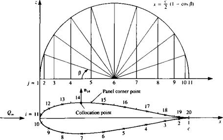
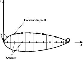
Discretization of geometry. As an example for this method, the 15 percent thick symmetric airfoil of Section 6.6 is considered. In most cases involving thick airfoils, a more dense paneling is used near the leading and trailing edges. A frequently used method for dividing the chord into panels with larger density near the edges is shown in Fig. 11.18. If ten chordwise panels are needed, then the semicircle is divided by this number, thus Aj8 = л/10. The corresponding x stations are found by using the following cosine formula:

jc=^(1 — cos/3) (11.25)

Once the x axis is divided into N panels with strength o), the N + 1 panel cornerpoints (x;=1) zy=1), (Xj=2> Zj=i)> ■ ■ ■ , {*j=N+1. Z;=v+i) are computed. The collocation points can be placed at the center of each panel (shown by the x mark on the airfoil surface in Fig. 11.18) and the values of these points (xi=u z,=1)> (x,_2, z,=2), . . . , (xi=N, zl=N) are computed too. The normal n„ which points outward, at each of these collocation points is found from the surface shape rj(x), as defined by Eq. (11.3).

Influence coefficients. In this phase the zero normal flow boundary condition is implemented. For example, the velocity induced by the /th element at the first collocation point can be obtained by using Eq. (1124) and is

(и, w)iy = SOR2DC (ay, де,, z„ x,, zjt xj+u z/+1) (11.26)

image432

FIGURE 11.18

“Full-cosine” method of spacing the panels on the airfoil’s surface.

The influence coefficient atj is defined as the velocity component normal to the surface. Consequently, the contribution of a unit strength singularity element j at collocation point 1 is = . Пі (11.27)

Note that a closer observation of Eqs. (11.21-11.23) shows that the normal velocity component at the ith panel is found by rotating the velocity induced by a unit strength j element by (a, – a,); therefore

aly = [-sin (ay – aj), cos (a, – a0](Ul’) (11.27«)

Here the velocity components (и, w)p are obtained from Eqs. (11.21) and (11.22). To evaluate the influence of the element on itself, Eq. (10.24) is recalled,

wp(x, 0±) = ±^ (11.28)

Based on this equation, the boundary condition (e. g., in Eq. (11.4)) will be specified at a point slightly above the surface (z = 0+ in the panel frame of reference). Consequently, when і = j the influence coefficient becomes

a„ = i (11-29)

Establish boundary condition (RHS). Specifying the boundary condition, as stated in Eq. (11.4), at collocation point 1, results in the following algebraic equation

ox + ax2o2 + Яіз<7з‘ ‘ ‘ + Uin^n + (C4., W*) • ^ = 0

where of course We = 0. The free-stream normal velocity component is transferred to the right-hand side and the vector RHS, is found, as in the previous example (by using Eq. (11.66)):

RHS, = – Uac sin a,

Both the influence coefficients and the RHS vector can be computed by a double “DO loop” where the collocation points are scanned first (and the RHS, vector is calculated) and then at each collocation point the influences of the singularity elements are scanned.

Solve equations. Specifying the boundary condition for each (і = 1 —> N) of the collocation points results in a set of algebraic equations with the unknown oy (j = 1 —> TV). These equations will have the form

image433

The above set of algebraic equations has a well-defined diagonal and can be solved for Oj by using standard methods of linear algebra.

Calculation of pressures and loads. Once the strength of the sources a, is known, the velocity at each collocation point can be calculated using Eq.

(11.24)and the pressure coefficient can be calculated by using Eq. (11.18). Note that this method is derived here for nonlifting shapes and the Kutta

condition is not used. Consequently, the circulation of the airfoil will be zero and hence no lift and drag will be produced. However, the pressure distribution is well predicted as shown in the following Example 1.

The formulation presented here allows for the treatment of an asym­metric body and in the case of symmetry the number of unknowns can be reduced to N/2 by a minor modification in the process of the influence coefficient calculation (in Eq. (11.27)). In this case the velocity induced by the panel (u, w)ij and by its mirror image (u, w);y will be calculated by using Eq.

(11.24) :

(и, w)v = SOR2DC (a, = 1, Xi, z„ xp zy, xl+l, zy+1)

(u, w)i = SOR2DC (oj = 1, Xi, zit xr -z,, x)+u – zy+1) and the influence coefficient ai; is then

av = [(и, w)ij + (u, и%] • n,

The rest of the procedure is unchanged, but with this modification we end up with only N/2 unknowns a, (e. g., for the upper surface only).

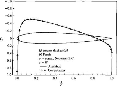
Example 1 Pressure distribution on symmetric airfoil. The above method is applied to the symmetric airfoil of Section 6.6. The computed pressure distribu-

image434

FIGURE 11.19

Pressure distribution on a symmetric airfoil (at a = 0).

tion is shown by the triangles in Fig. 11.19 and they agree well with the exact analytical results, including the leading and trailing edge regions.

Note that in this case, too, for a closed body the sum of the sources must be zero (E/li <7, = 0), and this condition may be useful for evaluating numerical results.

A sample student computer program that was used for this calculation is provided in Appendix D (Program No. 2).

CONSTANT-STRENGTH SINGULARITY SOLUTIONS (USING THE NEUMANN BOUNDARY CONDITION)

A more refined discretization of a continuous singularity distribution is th6 element with a constant strength. This type of element is shown schematically in Fig. 11.16, and it is assumed that s j

Подпись: o(x) dx,

image427

■—і—Ґ

X2 X *l*i

and as (x2 — xj—>0 the approximation seems to improve. In this case, only one constant (the strength of the element) is unknown and by dividing l

FIGURE 11.16

Constant-strength singularity approximation for a continuous strength distribution.

surface into N panels and specifying the boundary conditions on each of the collocation points, N linear algebraic equations can be constructed.

In principle, the point singularity methods are satisfactory in estimating the zero-thickness camberline lift, but are inadequate near the stagnation points of a thick airfoil. The constant-strength methods are capable of more accuracy near the stagnation points and can be used to model closed surfaces with thickness resulting in a more detailed pressure distribution, which is essential for airfoil shape design.

Discrete Source Method

Based on the principles of the previous section, let us develop a discrete source method for solving the symmetric, nonzero thickness airfoil problem of Section

5.1. For developing this method, too, let us follow the six steps suggested in Section 9.7 and apply them to the solution of the thin symmetric airfoil.

Selection of singularity element. The results of Chapter 5 indicate that the solution of the thin symmetric airfoil problem can be based on (discrete) source elements. The velocity induced by such an element placed at (x;, Zj) and with a strength of О/ is given by Eqs. (10.2) and (10.3) and can be expressed in matrix form as

where

rj = (x – Xj)2 + (z – Zj f

The above calculation can be included in a subroutine such that

(и, w) = SORC2D (pj, x, z, Xj, zf) (11.15)

and (x, z) is the field point of interest.

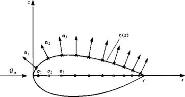
Discretization of geometry. First and most important is the definition of the coordinate system, which is shown in Fig. 11.13. Since the problem is

image425

FIGURE 11.13

Discrete source model of symmetric airfoil at zero angle of attack.

FIGURE 11.14

image426Relocation of the first and last collocation point to improve the numerical solution with the discrete source method.

symmetric, the unknown Oj elements are placed along the x axis, at the center of N equal segments at xj=1, xj=2, */=з» • • • > xj=N.

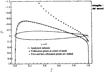
Next, the collocation points need to be specified. In this case it is possible to leave these points on the airfoil surface as shown in Fig. 11.13, and the values of these points (x,=1, z,=1), (x,=2, zi=2), ■ ■ ■ , (*.=n> z.=n) need to be established. The normal n, pointing outward, at each of these points, is found from the surface shape t}(x), as defined by Eq (11.3). As is demonstrated by the example at the end of this section, the solution can be improved considerably by moving the first and the last collocation points toward the leading and trailing edges, respectively (see Fig. 11.14).

Influence coefficients. In this phase the zero normal flow boundary condition is implemented in a manner depicted by Eq. (11.4). For example, the velocity induced by the jth element at the first collocation point can be obtained by using Eq. (11.15) and is

(и, w)iy = SORC2D (a,, xCi, zt, xjt z,) (11.16)

The influence coefficient aif is defined as the self-induced velocity component normal to the surface. Consequently, the contribution of a unit strength singularity element a, = 1, at collocation point 1 is

av = (и, w)v • n,

The induced normal velocity component qnl, at point 1, due to all the elements is then

Япі — au°l + a2°2 + a13°3 ■ ■ • + ЯіN°N

and the strength of a, is unknown at this point.

Establish boundary condition (RHS). Fulfilling the boundary condition on thf surface requires that at each collocation point the normal velocity component

will vanish. Specifying this condition for the first collocation point yields auox + al2o2 + al3o3- ■ ■ + alNaN + Wy • пг = 0

where of course Wx = 0. But the last term (free-stream component) is known and can be transferred to the right-hand side of the equation. Using the definition of Eq. (11.6) for the right-hand side it becomes

RHS, = -(£/., W. r) • n, = – Ц» sin a, (11.6b)

і RHS*

Discrete Source Method Подпись: О l' CT2 a3 Подпись: RHSi RHS2 RHS3 Discrete Source Method

Specifying the boundary condition for each of the collocation points results in a set of algebraic equations, similar to the previous discrete vortex example:

This procedure is automated by a double “DO loop” where the collocation points are scanned first and then at each collocation point the influences of the singularity elements are scanned.

Solve equations. The above set of algebraic equations can be solved for a, by using standard methods of linear algebra. It is assumed here that the reader is familiar with such methods, and as an example a direct solver can be found in the computer programs of Appendix D.

Calculation of pressures and loads. Once the strength of the sources o, is known, the total tangential velocity Q, at each collocation point can be calculated using Eq. (11.15) and Eq. (11.3a):

Qu = [2 («> ")ц + (t/-, Ж,)] • t, (11.17)

The pressure coefficient then becomes

Q?

Cp = 1-gr (И.18)

Since this flow is symmetric, no lift and drag will be produced (based on the conclusions of Section 5.1). Therefore, no further load calculations are included for this case.

Also, note that for a closed body the net flow generated inside the body

N

must be zero (E <7, = 0), and this condition may be useful for evaluating 1 = 1

numerical results.

Example 1 15 percent thick symmetric airfoil. The above method is applied to the 15 percent-thick airfoil of Section 6.6. If the collocation points are left above
the source points, as in Fig. 11.13, then the results shown by the triangles in Fig. 11.15 are obtained. This solution, clearly, is highly inaccurate near the leading edge. However, by moving the front collocation point more forward (to the 0.9 panel length location) and the rear collocation point closer to the trailing edge (to the 0.9 panel length location), as shown in Fig. 11.14 (and not moving the source points), a much improved solution is obtained. This solution, when compared with the exact solution of Section 6.6 is satisfactory over most of the region, excluding some minor problems near the trailing edge (Fig. 11.15).

Discrete Vortex Method

The discrete vortex method, which is presented here for solving the thin lifting airfoil problem, is based on the lumped-vortex element and serves for solving numerically the integral equation (Eq. ((5.39)) presented in Chapter 5. The advantage of the numerical approach is that the boundary conditions can be specified on the airfoil’s camber surface without a need for small-disturbance approximation. Also, two-dimensional interactions such as ground effect or multielement airfoils can be studied with great ease.

This method was introduced as an example in Section 9.8 and therefore its principles will be discussed here only briefly. To establish the procedure for the numerical solution, the six steps presented in Section 9.7 are followed:

Choice of singularity element. For this discrete-vortex method the lumped – vortex element is selected and its influence is given by Eq. (9.31) (or Eqs.

(10.9)

Подпись: where Подпись: rj = (x-xi)2 + (z-zir Подпись: (И.1)

and (10.10)):

Thus, the velocity at an arbitrary point (x, z) due to a vortex element of circulation Г; located at (xy, z,) is given by Eq. (11.1). This can be included in a subroutine, which will be called VOR2D:

(и, w) = VOR2D (Г;, x, z, Xj, z,) (11.2)

Such a subroutine is included in Program No. 13 in Appendix D.

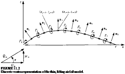
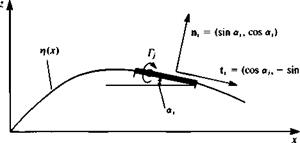
Discretization and grid generation. At this phase the thin-airfoil camberline (Fig. 11.2) is divided into N subpanels, which may be equal in length. The N vortex points (xj, Zj) will be placed at the quarter-chord point of each planar panel (Fig. 11.2). The zero normal flow boundary condition can be fulfilled on the camberline at the three-quarter chord point of each panel. These N collocation points (xh z,) and the corresponding N normal vectors n, along with the vortex points can be computed numerically or supplied as an input file. The vectors normal to the surface n, pointing outward at each of these points is found from the surface shape rj(x), as shown in Fig. 11.3:

Подпись: n,=Подпись: = (sin or,, cos or,-)image411(11.3)

where the angle a, is defined as shown in Fig. 11.3. Similarly the tangential vector t, is

t, = (cos ah – sin or,) (11.3a)

Подпись:
Since the lumped-vortex element chooses the correct circulation (Kutta condition), the last panel will inherently fulfill this requirement, and no additional specification of this condition is needed.

image413

FIGURE 11J

Nomenclature used in defining the geometry of a point singularity based surface panel.

Influence coefficients. The normal velocity component at each point on the camberline is a combination of the self-induced velocity and the free-stream velocity. Therefore, the zero normal flow boundary condition can be presented

as

q • n = 0 on solid surface

Division of the velocity vector into the self-induced and free-stream com­ponents yields

(и, w) • n + (£/„, Же) • n = 0 on solid surface (11.4)

where the first term is the velocity induced by the singularity distribution on itself (hence “self-induced part”) and the second term is the free-stream component Q„e = (t/„, WJ), as shown in Fig. 11.2.

The self-induced part can be represented by a combination of influence coefficients, while the free-stream contribution is known and will be transferred to the right-hand side (RHS) of the boundary condition. To establish the self-induced portion of the normal velocity, at each collocation point, consider the velocity induced by the jth element at the first collocation point (in order to get the influence due to a unit strength Г; assume Г, = 1 in Eq. (11.2)):

(u, hOj, = VOR2D (Гу = 1, xu zu Xj, Zj) (11.2a)

The influence coefficient a, у is defined as the velocity component normal to the surface. Consequently, the contribution of a unit strength singularity element at collocation point 1 is

«1/ = (u, w)y • Пі (11.5)

The induced normal velocity component qnl, at point 1, due to all the elements is therefore

Чп = ЯцГі + Д12Г2 + Я13Г3 + • • • + йілгГ^

Note that the strength Г; is unknown at this point.

Fulfillment of the boundary condition on the surface requires that at each collocation point the normal velocity component will vanish. Specification of this condition (as in Eq. 11.4) for the first collocation point yields

ЯцГі + Q 12^*2 + Я13Г3 + • • • + aiNTN + (U„, Ж») • nj = 0

But, as mentioned earlier, the last term (free-stream component) is known and can be transferred to the right-hand side of the equation. Consequently, the right-hand side is defined as

RHS, = Ж») • n, (11.6)

Specifying the boundary condition for each of the N collocation points results in the following set of algebraic equations:

‘ «11

a12

«ш

/г Д

RHS

Я21

Я22

a2N I

RHS

«31

a32

a3N I

RHS

flvi

Я N2 ‘ • •

aNNj

r„l

RHS

This influence coefficient calculation procedure can be accomplished by using two “DO loops” where the outer loop scans the collocation points and the inner scans the vortices:

DO 1 і = 1, N collocation point loop

DO 1 j = 1, N vortex point loop

(u, w)0 = VOR2D (Г = 1.0, Xi, Zj, xjt z,)

^1) (^’ W)ij ‘

1 CONTINUE C END DO LOOP

Establish RHS vector. The right-hand side vector, which is the normal component of the free stream, can be computed within the outer loop of the previously described “DO loops” by using Eq. (11.6):

RHS,, = -(£/„, Ж.) • n,

where (£/„, Ж»,) = QJcos a, sin a). Using the formulation of Eq. (11.3) for the normal vector, the RHS becomes:

RHS, = -£2»(cos a sin <xt + sin a cos a,) (11.6a)

Note that a is the free-stream angle of attack (Fig. 11.2) and cr, is the ith panel inclination.

Solve linear set of equations. The results of the previous computations can be

T r2 Г, Г4 r5

>C ■ i0 10 1C

image414~4 Ac K

FIGURE 11.4

Representation of a lifting flat plate by five discrete vortices.

Discrete Vortex Method Подпись: (11.7)

summarized (for each collocation point i) as

Подпись: 1 л Ac Подпись: * ї -і і -3 -li Подпись: Г і l Подпись: = -Q„ sin or
image415

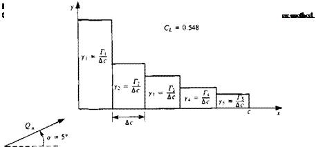
and as an example for the case of a flat plate (shown in Fig. 11.4) where only five equal-length elements (Ac = c/5) were used Eq. (11.7) becomes

This linear set of algebraic equations is diagonally dominant and can be solved by standard matrix methods, and the solution of the above set of algebraic equations is

ГД

2.46092

1.09374

Г3 1 = яДс<2» sin a

0.70314

w

0.46876

Г si

,0.27344

This solution is shown schematically in Fig. 11.5

Secondary computations: pressures, loads, velocities, etc. The resulting pres­sures and loads can be computed by using the Kutta-Joukowski theorem for

each panel j. Thus the lift and pressure difference are

Подпись: (11.8) (11.9) image416
ALj = pQSj

where Ac is the panel length. The total lift and moment per unit span (about the leading edge) are obtained by summing the contribution of each element:

l = 2al, (ИЮ)

7 = 1 N

M0 = 2 ALj(Xj cos a) (11.11)

y=i

Discrete Vortex Method Подпись: (11.12) (11.13)

while the nondimensional coefficients become

The following examples are presented to demonstrate possible applications of this method.

Example 1 Thin airfoil with parabolic camber. Consider the thin airfoil with parabolic camber of Section 5.4, where the camberline shape is

image417

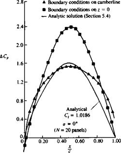
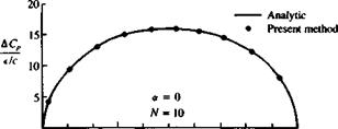
For small values of є <0.05 the numerical results are close to the analytic results, as shown in Fig. 11.6. However, when increasing the airfoil height e to 0.1, the effects of the small-disturbance approximation to the boundary conditions become more evident (see Fig. 11.7). Note that for the numerical solution the vortices were placed on the camberline where the boundary condition was satisfied, whereas for the analytical solution the vortex distribution and boundary conditions were specified on the x axis.

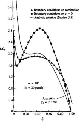
The effect of angle of attack is shown in Fig. 11.8 where a fairly large angle

image418

image419

FIGURE 11.7

Effect of small-disturbance bound­ary condition on the computed pressure difference of a thin para­bolic camber airfoil (a = 0).

Подпись: FIGURE 11.8 Effect of small disturbance boundary condition on the computed pressure difference on a thin parabolic camber airfoil (a =10”).
image420

(ar = 10°) is used. Note the large suction peak at the leading edge, which is exaggerated by the analytic solution.

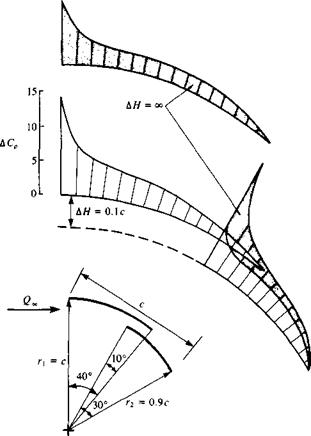
Example 2 Two-element airfoil. The advantage of this numerical solution technique is that it is not limited to the restrictions of small-disturbance boundary conditions. For example, a two-element airfoil with large deflection can be analyzed (and the results will have physical meaning when the actual flow is attached).

Figure 11.9 shows the geometry of the two-element airfoil made up of circular arcs and the pressure difference distributions. The interaction is shown by the plots of the close and separated elements (far from each other). When the elements are apart, the lift of the flrst element decreases and of the second increases.

Example 3 Sensitivity to grid. After this first set of numerical examples, some possible pitfalls of the numerical approach can be observed, and hopefully avoided later.

First note the method of paneling the gap region in the previous example of the two-element airfoil (Fig. 11.10). If very few elements are used, then it is

Discrete Vortex Method

image421

FIGURE 11.9

Effect of airfoil/flap proximity on their chordwise pressure difference.


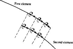
image422FIGURE 11.10

Method of paneling the gap region of a two-element airfoil (discrete vortex model).

image423

FIGURE 11.11

Schematic survey of induced normal velocity above a thin airfoil (as shown in Fig. 11.4) modeled by discrete vortices.

always advised to align the vortex points with vortex points and collocation points with collocation points. We must remember that a numerical solution depends on the model and the grid (and hence is not unique). The convergence of a method can be tested by increasing the number of panels, which should result in a converging solution. Therefore, it is always advisable to use smaller panels than the typical length of the geometry that we are modeling. In the case of the two-element airfoil, the typical distance is the gap clearance, and (if possible with the more refined methods) panelling this area by elements of at least one-tenth the size of the gap is recommended.

Another important observation can be made by trying to calculate the velocity induced by the five-element, vortex representation of the flat plate of Fig. 11.4. If the velocity survey is performed at z = 0.05c, then the wavy lines shown in Fig. 11.11 are obtained. The waviness will disappear at larger distances, and in

image424

FIGURE 11.12

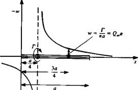
Downwash induced by a lumped-vortex element.

any computation careful investigation is needed for the near – and far-field effects of a particular singular element distribution.

Of course, in the previous examples, fairly accurate solutions were obtained with very few panels. This is because the lumped-vortex element induces the same downwash at the collocation point (3/4,0)a as the exact flat plate solution, as depicted by Fig. 11.12.

POINT SINGULARITY SOLUTIONS

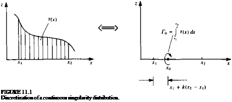
The basic idea behind point singularity solutions is presented schematically in Fig. 11.1. If an exact solution in the form of a continuous singularity distribution (e. g., a vortex distribution y(x)) exists, then it can be divided into several finite segments (e. g., the segment between >x2). The local average strength of the element is then Г0 = у(дг) dx and it can be placed at a point x0 within the interval xx-x2. A discrete-element numerical solution can be obtained by specifying N such unknown element strengths and then estab-

Подпись: FIGURE 11.1 Discretization of a continuous singularity distribution.
lishing N equations for their solution. This can be done by specifying the boundary conditions at N points along the boundary (and these points are called collocation points). Also, when constructing the solution, some of the considerations mentioned in Section 9.3 (e. g., in regard to the Kutta condition and the wake) must be addressed.

As a first example, this very simple approach is used for solving the lifting and thickness problems of thin airfoils, which were treated analytically in Chapter 5.

SOLUTIONS

The principles of singular element based numerical solutions were introduced in Chapter 9 and the first examples are provided in this chapter. The following two-dimensional examples will have all the elements of more refined three – dimensional methods, but because of the simple two-dimensional geometry the programming effort is substantially less. Consequently, such methods can be developed in a short time for investigating improvements in larger codes and are also suitable for homework assignments and class demonstrations.

Based on the level of approximation of the singularity distribution, surface geometry, and type of boundary conditions, a large number of computational methods can be constructed, some of which are presented in Table 11.1. We will not attempt to demonstrate all the possible combinations but will try to cover some of the most frequently used methods (denoted by the word “Example” in Table 11.1) which include: discrete singular elements, and constant strength, linear, and quadratic elements (as an example for higher – order singularity distributions). The different approaches in specifying the zero normal velocity boundary condition will be exercised and mainly the outer Neumann normal velocity and the internal Dirichlet boundary conditions will be used (and there are additional options, e. g., an internal Neumann condition). In terms of the surface geometry, for simplicity, only the flat panel element will be used here and in areas of high surface curvature the solution can be improved by using more panels.

TABLE 11.1

List of possible two-dimensional panel methods tested in this chapter

Singularity

distribution

Boundary conditions

Neumann Dirichlet (external) (internal)

Surface paneling Flat/high-order

Point

source

Example

Flat

doublet

vortex

Example

Flat

Constant

source

Example

Example

Flat

strength

doublet

Example

Example

Flat

vortex

Example

Flat

Linear

source

Example

Example

Flat

strength

doublet

Example

Example

Flat

vortex

Quadratic

source

strength

doublet

Example

Flat

vortex

In this chapter and in the following chapter the primary concern is the simplicity of the explanation and the ease of constructing the numerical technique, while numerical efficiency considerations are secondary. Conse­quently, the numerical economy of the methods presented can be improved (with some compromise in regard to the ease of code readability). Also, the methods are presented in their simplest form and each can be further developed to match the requirements of a particular problem. Such improve­ment can be obtained by changing grid spacing and density, location of collocation points, wake model, method of enforcing the boundary conditions, and of the Kutta condition.

Also it is recommended to read this chapter sequentially since the first methods will be described with more details. As the chapter evolves, some redundant details are omitted and the description may appear inadequate without reading the previous sections.

THREE-DIMENSIONAL HIGHER – ORDER ELEMENTS

The surface shape and singularity strength distribution over an arbitrarily shaped panel can be approximated by a polynomial of a certain degree. The surface of such an arbitrary panel as shown in Fig. 10.27a can be approximated by a “zero-order” flat plane

z = a0

by a first-order surface

z = a0 + blx + b2y

by a second order surface

z = a0 + bxx 4- b2y + cxx2 + c2xy + c3y2

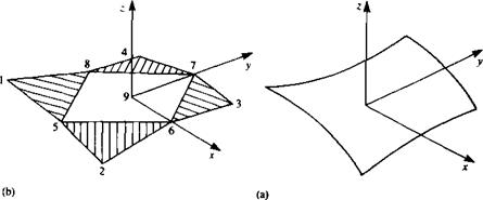
or any higher-order approximations. Evaluation of the influence coefficients in a closed form is possible,10 1 though, for flat surfaces and an approximation of a curved panel by five flat subpanels is shown in Fig. 10.27fi. This approach is used in the code PANAIR9 2 and for demonstrating a higher-order element let us describe this element.

For the singularity distribution a first-order source and a second-order doublet is used, and in the following paragraph the methodology is briefly described:

INFLUENCE OF SOURCE DISTRIBUTION. The source distribution on this element is approximated by a first-order polynomial:

o(x0, y0) = 0o + axx0 + <7ууо (10.121)

image406

FIGURE 10.27

Approximation of a curved panel by five flat subpanels.

where (*0, y0) are the panel local coordinates, o0, the source strength at the origin, and o0, ox and ay are three constants. The contribution of this source distribution to the potential АФ and to the induced velocity Д(и, v, w) (in the panel frame of reference) can be evaluated by performing the integral

Подпись: ДФ(х, уПодпись:image407(10.122)

and then differentiating to get the velocity components

Подпись: Д(м, v, wПодпись: ЭФ ЭФ ЭФ ~Эх’~Э^’~Эг)image408(10.123)

The result of this integration depends solely on the geometry of the problem and can be evaluated for an arbitrary field point. Some details of this calculation are provided by F. T. Johnson9 2 and can be reduced to a form that depends on the panel comer point values (the comer point numbering sequence is shown in Fig. 10.27b.). Thus, in terms of these cornerpoint values the influence of the panel becomes

ДФ = Fs(<*i, o2, a3, o4, o9) =/s(0o, ax, oy) (10.124)

Д(и, v, w) = GS(01, 02, 03, oA, a9) = gs(o0, 0,, Oy) (10.125)

where the functions F, G, and /, g are linear matrix manipulations. Also, note that 0O, 04, Oy are the three basic unknowns for each panel and olt…, o9 can be evaluated based on these values (so that for each panel only three unknown values are left).

INFLUENCE OF DOUBLET DISTRIBUTION. To model the two components of vorticity on the panel surface a second-order doublet is used:

/*(*о> Уо) = Ио + ИхХ0 + ИуУо + ИххХІ + Цхух0Уо + ЦуууІ (10.126)

t*(xo, y0) • z dS

[(* — XqF + (y — Уо)2 + z2]

Подпись: 213/2 Подпись: (10.127)

The potential due to a doublet distribution whose axis points in the г direction (see Section 3.5) is

and the induced velocity is

Подпись: (10.128). / ЭФ ЗФ ЭФ

These integrals can be evaluated (see F. Johnson9 2) in terms of the panel comer points (points 1-9, in Fig. 10.27b) and the result can be presented as

ДФ = Fd(hi, p2, ti3, цА, fis, ц6, ц7, ця, ju9)

Подпись:fo(.F 0, Fxf Fy> dxx, dxy, dyy)

Д(и, v, w) = Gd(Mi, fi2, Мз, Мд, Ms, Мб, M7, Me, M9)

?d(Mo, Mj, My, M-tjc> Мдгу, Myy) (10.130)

where the functions F, G, and /, g are linear matrix manipulations, which depend on the geometry only. Also, note that fi0, цх, /лу, цхх, цху, fiyy are the five basic unknowns for each panel and цІУ . . . , /х9 can be evaluated based on these values (so that for each panel only five unknown doublet parameters are left).

For more details on higher-order elements, see Ref. 9.2.

REFERENCES

10.1. Hess, J. L., and Smith, A. M. O., “Calculation of Potential Flow About Arbitrary Bodies,” Progress in Aeronautical Sciences, vol. 8, pp. 1-138, 1967.

10.2. Browne, Lindsey E., and Ashby, Dale L., “Study of the Integration of Wind-Tunnel and Computational Methods for Aerodynamic Configurations,” NASA TM 102196, July 1989.

10.3. Sarpkaya, T., “Computational Methods With Vortices—The 1988 Freeman Scholar Lec­ture,” Journal of Fluids Engineering, vol. Ill, pp. 5-52, March 1989.

PROBLEMS

10.1. Find the x-component of velocity и for the constant-strength source distribution by a direct integration of Eq. (10.12).

10.2. Find the velocity potential for the constant doublet distribution by a direct integration of Eq. (10.25).

10.3. Consider the horse shoe vortex of Section 10.47, which lies in the x-y plane. For the case where the leading segment lies on the x axis (xa = 0) find the velocity induced at a point whose coordinates are x, y, and z that lies above the plane of the horse shoe.

THREE-DIMENSIONAL HIGHER - ORDER ELEMENTS

Horseshoe Vortex

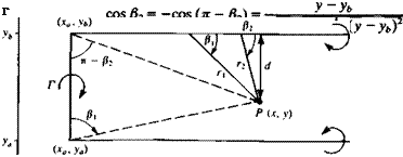
A simplified case of the vortex ring is the horseshoe vortex. In this case the vortex line is assumed to be placed in the x-y plane as shown in Fig. 10.26. The two trailing vortex segments are placed parallel to the x axis at у = ya and at У ~Уъ> and the leading segment is placed parallel to the у axis between the points {xa, уa) and (xa, yb). The induced velocity in the x-y plane will have only a component in the negative z direction and can be computed by using Eq. (2.69) for a straight vortex segment:

Подпись: (10.118)

w(x, y, 0) = — (cos /3, – cos /32) 4 Ли

image401

where the angles and their cosines are shown in the Fig. 10.26. For example, for the semi-infinite filament shown,

Подпись: cos /32 = cos л = — 1

For the vortex segment parallel to the x axis, and beginning at у=уь, the corresponding angles are

image403,image404 Horseshoe Vortex

For the finite-length segment parallel to the у-axis,

FIGURE 10.26

Nomenclature used for deriving the influence of a horseshoe vortex element.

Horseshoe Vortex
Подпись: - У»)2]
Horseshoe Vortex
Подпись: j (10.119а)

where the finite-length segment does not induce downwash on itself.

The velocity potential of the horseshoe vortex may be obtained by reducing the results of a constant strength doublet panel (Section 10.4.2) or by integrating the potential of a point doublet element. The potential of such a point doublet placed at (jc0, y0, 0) and pointing in the z direction, as derived in Section 3.5 (or in Eq. (10.110)) is

4л r3

where r = V(jc – xQ)2 + (y — y0)2 + z2. To obtain the potential due to the horseshoe element at an arbitrary point P, this point doublet must be integrated over the area enclosed by the horseshoe element:

<b = ZT p Г________________ zdxо_________

Horseshoe Vortex
4/r і Уо1 [(x – x0f + (y – y0)2 + г2Га The result is given by Moran,51 p. 445, as

Note that we have used Eq. (B.4a) from Appendix В to evaluate the limits of the first term.

Vortex Ring

Based on the subroutine of Eq. (10.116), a variety of elements can be defined. For example, the velocity induced by a rectilinear vortex ring (shown in Fig. 10.24) can be computed by calling this routine four times for the four

image398

(X4<yi. Zi)

image399FIGURE 10.24

Influence of a rectilinear vortex ring.

segments. Note that this velocity calculation is equivalent to the result for a constant-strength doublet.

To obtain the velocity induced by the four segments of a rectangular vortex ring with circulation Г calculate

(«1, Vi, Wj) = VORTXL (x, y, z, xu yb zu x2, y2, z2, Г)

(u2, v2, w2) = VORTXL (x, y, z, x2, y2, z2, x3, y3, z3, Г)

(u3, v3, w3) = VORTXL (x, y, z, x3, y3, z3, x4, y4, z4, Г)

(u4, v4, w4) = VORTXL {x, y, z, x4, y4, z4, xu yu zu Г)

and the induced velocity at P is

(u, V, w) = (lli * VU Wi) + (u2, v2, w2) + (u3, V3, Wj) + (u4, v4, tv4)

This can be programmed into a subroutine such that

Подпись: (10.117)Подпись: = VORINGX у z *1 У z2 x2 У2 Z2 *3 Уз z3 X4 y4 z4
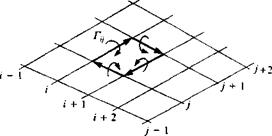
In most situations the vortex rings are placed on a patch with i, j indices, as shown in Fig. 10.25. In this situation the input to this subroutine can be abbreviated by identifying each panel by its i, jth corner point.

(u, v, w) = VORING (x, y, z, i, j, Г,,) (10.117a)

From the programming point of view this routine simplifies the scanning of the vortex rings on the patch. However, the inner vortex segments are scanned twice, which makes the computation less efficient. This can be improved for larger codes when computer run time is more important than programming simplicity.

Note that this formulation is valid everywhere (including the center of the element) but is singular on the vortex ring. Such a routine is used in Program No. 12 in Appendix D.

image400FIGURE 10.25

The method of calculating the in­fluence of a vortex ring by adding the influence of the straight vortex seg­ment elements.