Category AERODYNAMICS

Airfoil With Finite Trailing-Edge Angle

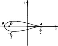
The Joukowski airfoils have cusped trailing edges as has been seen for the flat plate, circular arc, and symmetric examples. The cusped trailing edge presents some numerical difficulties for panel-method solutions since in the neighbor­hood of the trailing edge the airfoil’s upper and lower surfaces coincide. Therefore, for the purpose of providing exact solutions to test the results of the panel methods to be

Symmetric Joukowski Airfoil

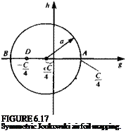
For an airfoil of chord c and thickness parameter є the radius of the circle in the /plane is a (Fig. 6.17) where

c’=1- fl*.

Подпись:Подпись: (6.58)Подпись: (6.71a)

Airfoil With Finite Trailing-Edge Angle
Подпись: (6.69a)
Подпись: (6.696)
Подпись: where

a = ^(l + e)

where the airfoil chord c is

с = ^(з + 2е+ 1 )

4 1 + 2є/

The x, z coordinates of the airfoil are given in Eq. (6.57) as

C2

/ fC , 16

x = a cos 0 ——I 1 H————— —;———-

V 4 / / єС2 .

^a cos 0 – — j + a cos

Airfoil With Finite Trailing-Edge Angle
Подпись: (6.72 b)

В = 2a sin 0( a cos 0 ——

and the pressure coefficient is calculated by using Eq. (6.70).

The Van de Vooren Airfoil

a2k

(1 + є)*’1

Подпись: 21 = Подпись: (6.73)

The parameters for this airfoil are shown in Fig. 6.18 where the chord length is 21 and is given from Eq. (6.65) as

Here є is the thickness parameter and к is the trailing-edge angle parameter (see Eq. (6.66)) and a is the radius of the circle in the / plane.

The x, z coordinates of the Van de Vooren airfoil are then given in Eq. (6.63) as

rk

x = -£гт [cos k6x cos (к — 1)02 + sin квх sin (к — 1)02] (6.74a)

r2

rk

z = [sin квх cos (к — 1 )02 – cos k6x sin (к – 1 )02] (6.746)

Подпись: where

f"i = V(a cos в — a)2 + a2 sin5 0

r2 = V(a cos 0 – єа)2 + a2 sin2 0

„ a sin 0

0i = tan —————- v я

Airfoil With Finite Trailing-Edge Angle

a cos 0 — a

Here Пі depends on the quadrant where 02 is being evaluated (has a value of 0 in the first quadrant, 1 in the second and third quadrants and 2 in the fourth quadrant).

r* sin a – sin (a — 0)

w = -2 <2*

Airfoil With Finite Trailing-Edge Angle Подпись: (6.75a) (6.756)

The velocity distribution is then given from the solution in the circle plane plus the transformation (Eq. (6.62)) as

Symmetric Joukowski Airfoil

1

Let the center of the circle be taken on the real axis,

(x = – eC/4 €>0 (6.56)

so that from Eq. (6.27)

/3 = 0 a=^(l + e) (6.56a)

The circle is transformed into the airfoil shape shown in Fig. 6.17 (note that e should be small). The surface of the airfoil is given by (Eq. (6.24))

Подпись: r=- +C2

Подпись:єС C 4 +

Symmetric Joukowski Airfoil Подпись: (6.57)

= — [—e + (1 + e) cos в + i(l + б) sin 0]

image229
Подпись: FIGURE 6.17 Symmetric Joukowski airfoil mapping.

Note that Y(-6) = У and therefore the resulting airfoil is symmetric. The chordlength c is given by

с = У(0 = О) + |У(0 = я)|=^{(1 + 2є)[і + ^-^]+2}

-£{3 + 2e + (TT2o) (6’58)

For small e, the chordlength is approximated by

c = j {3 + 2e + 1 – 2e + 4e2 + • • •} = C{ 1 + 4e2 + ■ ■ •} (6.59)

Symmetric Joukowski Airfoil Подпись: (6.60)

We can therefore take c = C. The velocity at the cusped trailing edge is given by Eq. (6.32) as

and the lift coefficient is (when C is the chord) given by Eq. (6.29a) as

С, = 2я(1 + e) sin a (6.61)

The thickness ratio is approximately equal to 1.299e.

Circular Arc Airfoil

Circular Arc Airfoil

The center of the circle is chosen on the imaginary axis in the f plane fi = im and from Eq. (6.27) a = Cl4 sec /3 and m = a sin /3. This results in the circulai arc airfoil shown in Fig. 6.14a with chord с = C. Note that since the circlf passes through both critical points A and D, the corresponding points on thjf airfoil are sharp. Also, points B[f = i(a + m)] and E[f = — i(a – m)] on th{! circle, at the top and bottom, both transform to the same point on the аігіоЦ Y = 2im. The schematic streamline pattern for the flow in both the physical and circle planes is shown in Fig. 6.146. Note that the forward stagnation point on the circle occurs when 0 = я + 2a + /3 and therefore the forward stagnatio| point on the circular arc can be found from the transformation. The velocity 4 the trailing edge is given by Eq. (6.32) as

The zero lift angle is seen to be equal to -/3. The maximum camber ratiq
defined as the ratio of the maximum ordinate 2m to the chord c and is tan|
An interesting special case occurs when the circular arc is set at an
of attack of zero. From above, it appears that the forward stagnation poin

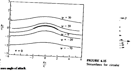
image224

circular arc airfoil’XeT(Tan angle^f’Xck)deSCriPti0n °f S, reamlines in the circle and the

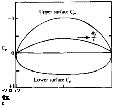
FIGURE 6.16

Подпись: -2 0 +2 4x c Pressure coefficient for circular arc at zero angle of attack.

at the leading edge but since a critical point exists there, L’Hospital’s Rule must be used again and with / = – cl4 and в = n + /3, the complex velocity at the leading edge is

w(y == Qao cos2 Ре~ър (6.55)

This is equal in magnitude to the velocity at the trailing edge and the flow is seen to be symmetric with respect to the z axis. This is an example of a lifting flow with no stagnation points (see the streamline pattern in Fig. 6.15) and with a flow path of equal length for particles traveling along the upper and lower surfaces. The pressure coefficient is plotted in Fig. 6. 6.

Flow Normal to a Flat Plate

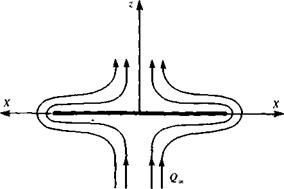
Another interesting solution that can be obtained by this method is the solution for the flow normal to a flat plate. The complex potential for this flow in the circle plane is obtained by adding the potentials of a stream in the z direction and an opposing doublet (the flow is symmetric about midchord and has zero circulation) and is given by

image220(6.47)

Подпись: -« =
image221
Flow Normal to a Flat Plate

On the surface of the circle / = (с/4)e, e and the complex potential becomes

The complex potential on the surface is seen to be real and therefore it is equal to the velocity potential. The jump in potential across the plate is therefore given by

Подпись: (6.49)ДФ = QccVl – {2x! c f

Both an application of the Kutta-Joukowski theorem and a pressure integration yield the result that there is no force acting on the plate (recall that this is a potential flow solution without any flow separations!). Based on the results of the previous section, however, it is expected that symmetrically placed tip forces may be acting on the tips of the plate and these will be important in the slender-wing application.

Consider the flow in the neighborhood of the left tip where / is approximately — c/4. The complex velocity at the corresponding point on the circle is obtained by a differentiation of the complex potential (Eq. (6.47)) as

Подпись: (6.50)W(f) = -2iQ

The analysis now proceeds in an identical fashion to the analysis in the previous section since the transformation is the same and the complex velocity in the neighborhood of the tip is

image222(6.51)

The tip force is then calculated and is

Подпись: (6.52)npcQl

image223

FIGURE 6.13

Suction force at the two tips of a flat plate in a normal flow (the two opposite forces cancel each other).


The force acts to the left and from symmetry a tip force of equal magnitude acts on the right tip and points to the right (see Fig. 6.13).

Leading-Edge Suction

In the previous section the force on a flat plate airfoil is obtained with the use of the Kutta-Joukowski Theorem and is seen to be perpendicular to the free stream direction. An apparent problem arises if we attempt to find the force by an integration of the pressure distribution. On the surface of the plate the velocity is given in Eq. (6.35) and with the use of the Bernoulli equation the pressure difference across the plate is given as

V

I — ‘2jX/c

1 + 2x/c (6.38)

image217 Подпись: (6.39)

The force Z is perpendicular to the plate and is obtained by integrating the pressure difference along the plate to get

The force obtained by these two different approaches is not the same in either magnitude or direction.

The difference can be explained by considering the flat plate as the limiting case of a thin airfoil as its thickness goes to zero. In this limit the pressure at the leading edge increases while the area upon which it acts decreases until in the flat plate limit the pressure is infinite and the area is zero. In this limit there is a finite contribution to the force that must be added to the result obtained by the pressure integration. To obtain this force we surround the plate leading edge by a small circle and calculate the force with the use of the Blasius formula.

The complex velocity on the plate is given in Eqs. (6.31) and (6.31a). The velocity on the circle at the leading edge is obtained by using Eq. (6.31) with /3 = 0 and в = л and is

W(f) = —4iQx sin a (6.40)

Leading-Edge Suction Подпись: (6.41)

Near the leading edge / is approximately —c/4 and therefore we can take

If the transformation in Eq. (6.24) is now inverted and У is set approximately equal to — c/2, the transformation becomes

f = h{Y + УУ2-с2/4) = – C – + iifcyjY + d2 (6.42)

Подпись: The complex velocity in Eqs. (6.41) and (6.42))the leading-edge region is therefore seen to be (from

Подпись:e^y^sinnr

ЩУ) VT + c/2

This velocity is now substituted into the Blasius formula (Eq. (6.19)) to get

X – iZ = y J W2dY = Y Qlc sin2 or J = ~прс0& s*n2 01 (6-44)

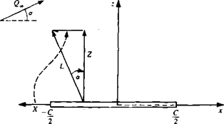
This leading edge force is seen to act along the plate in the upstream direction (Fig. 6.12) and is called the leading-edge suction force.

The total force is now obtained by the addition of the pressure force and the suction force (Eqs. (6.39) and (6.44)) and the resultant force is seen to be perpendicular to the stream and exactly equal to the result from the Kutta-Joukowski theorem (see Fig. 6.12).

A generalization of these results can be applied to the solution of the small-disturbance version of the thin-airfoil problem. Assume that this solution has the following complex velocity in the neighborhood of the airfoil leading edge,

Подпись: A Vy + c/2 Подпись:

image218,image219

W(Y) =

FIGURE 6.12

Forces due to pressure difference and leading edge suction on the flat plate at angle of attack. Note that the resultant force (lift) is normal to the free stream Q^.

where A is a constant. Then the leading-edge suction force in this situation is given by the Blasius formula as

Подпись: (6.46)X = —JtpA2

Flat Plate Airfoil

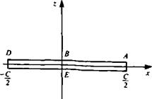
Подпись: a - C/4. Then from Eq. (6.33) Choose the circle with its center at the origin and (6-27),
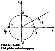
M = /3 = 0

Подпись: FIGURE 6ЛФ Flat plate airfoil mapping.
image215

The circle is given by / = C/4e, e and the corresponding airfoil is Y = C cos в/2 which is seen to be a flat plate of chord c = C (see Fig. 6.10). Note that

0 < 0 < я represents the top surface and я<0<2л represents the bottom. The complex velocity on the plate surface is obtained using Eqs. (6.31) and (6.31a) as

Подпись: = Q Подпись: [sin a — sin (a — 0)] sin 0 Подпись: (6.34)

2i’Q4sin a ~ sin (a – 6)]e~,e 2iQaa[sin a — sin (a — 6)]е~ів 1-е~ш 2i sin в е~ів

and since x — c/2 (cos 0) then sin 0 = ±Vl — (2x/c)2, and we have

Подпись:W. l-cos0 ll-2x/c

— = cos a + sin a—:—-— = cos a ± sin a -——- <2„ sin 0 V 1 + 2x/c

where the plus sign refers to the upper surface and the minus sign to the lower. Note that the trailing edge velocity is Q„ cos a and that the disturbance to the stream vanishes as the square root of distance from the trailing edge. Also, the velocity has a square root singularity at the plate’s sharp leading edge.

For small a, Eq. (6.35) becomes

Подпись: (6.34a)W „ 1 – cos 0

— = 1 + a———–

0» sin 0

Note that with the use of Eqs. (5.37), (5.48), and (5.71) (and considering the different definition of 0 in Chapter 5), the solution is identical to the flat plate solution from thin airfoil theory.

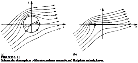
The streamline patterns in the circle and plate planes are shown schematically in Fig. 6.11. Note that the forward stagnation point in the circle plane is at 0 = л + 2a and therefore the forward stagnation point on the plate

Подпись: FIGURE 6.11 Schematic description of the streamlines in circle and flat plate airfoil planes.

is at x = — c/2(sin 2ar).

The circulation and lift force are given by Eqs. (6.28) and (6.29) as

Г = ncQ„ sin a (6.36)

L = лpcQt sin a (6.37)

and the lift coefficient is (Eq. (6.29a))

С/ = 2л sin a (6.37a)

CONFORMAL MAPPING AND THE JOUKOWSKI TRANSFORMATION

The method of solution for our model airfoil problem is to map the airfoil (which is in the physical plane Y = x + iz) to a circular cylinder in the / = g + ih plane through the conformal mapping Y = Y(f). The solution in the circle plane has already been obtained (in Section 3.11). Let the complex potential in the circle plane be F(f) and the complex velocity W(f). Then the results in the physical plane are

Подпись: (6.22) (6.23) F(Y) = F[f(Y)] dF dF df 1

w^dY=^d=w(f^f

The complex velocity in the physical plane is given as a function of the transformation variable f. The following three model problems are all special cases of the Joukowski transformation

Подпись: (6.24)C2

r‘f+w

where C will be shown to be the chord for a flat plate, circular arc, and approximately for a symmetrical foil.

CONFORMAL MAPPING AND THE JOUKOWSKI TRANSFORMATION Подпись: Q„a2eia (f~F)2 Подпись: (6.25)

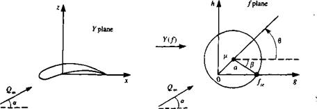
Consider the mapping from the airfoil to the circle shown in Fig. 6.9. The complex velocity at infinity in both planes is Q^e ‘a and the transformation has two free parameters, the radius of the circle a and the center of the circle p. The complex velocity in the circle plane is obtained with the aid of the results of the flow over a cylinder from Section 3.11:

Since the airfoil has a sharp trailing edge and the circle has no corners, the transformation must have a critical point (dY/df = 0) at the point in the circle plane corresponding to the airfoil trailing edge. Denote this point by fe- The Kutta condition requires the velocity at the airfoil trailing edge to be finite

image213

FIGURE 6.9

Joukowski transformation: mapping of airfoil to circle.

and therefore from Eq. (6.23) it can only be satisfied if

W(/„) = 0 (6.26)

In the circle plane fK = C/4 and the coordinate system is shown in Fig. 6.9. (Note that / = – C/4 is also a critical point and must be placed inside the circle to avoid a velocity singularity in the flowfield. The critical points f = ±C/4 transform to Y = ±C/2.) From the figure, it is seen that

fe-ti = ае~ф (6.27)

If this is substituted into Eq. (6.25) for W(f) and the Kutta condition is applied, we get

Q„e-ia + e* – Q-eiae2ip = 0

2 ла

-2jtaQJe~*a+l>) + Г + 2naQJeKa+p) = 0 and the circulation is

Г = 4ла(2«> sin (a + /3) (6.28)

The lift and lift coefficient are then given by

L = pQooT (6-29)

С, = т—^Г = 8л:-sin (a + (6.29 a)

pQlc c

Let the surface of the circle be given by

f = p + ae, e (6.30)

as shown in Fig. 6.9. The complex velocity on the circle is then obtained by

substituting Eqs. (6.28) and (6.30) into Eq. (6.25):

W(f) = Q„e~la + 2sin (a + р)е~ів – <2„е-іае~ш = Q„e-,e[e"'(e,“e) + 2/ sin (a + /3) – eKa~e)]

= 2j’6»(sin (or + /3) – sin (a — 0)]e_,e (6.31)

and the complex velocity on the airfoil surface is obtained from Eq. (6.23).

Подпись: W(Y) = -Подпись: (6.31a)

Подпись: 16/2 Подпись: 1 -

W(/)

CONFORMAL MAPPING AND THE JOUKOWSKI TRANSFORMATION

To find the complex velocity at the airfoil trailing edge, L’Hospital’s Rule must be applied since both W(f) and dY/df are zero there. At the trailing edge / = C/4 and в = 2л – /3 and the complex velocity is found to be

Using ft-p = aew, we get

= 2*"®[—і sin (a + /3) + e'(“ e)] = Qx,^e2ipcos (a + fi)

(6.32)

BLASIUS FORMULA KUTTA-JOUKOWSK1 THEOREM

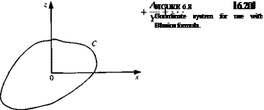
Consider the flow past a body whose contour is denoted by C (Fig. 6.8). Let the components of the aerodynamic force acting on the body be X and Z in the x and z directions, respectively. An integration of the pressure around the contour and an application of Bernoulli’s equation then leads to the Blasius formulas (see proof in Glauert,5 2 pp. 80-81):

X – iZ = ^ f [W(Y)]2 dY (6.19)

2 Jc

Подпись: C- image211,image212

Let the free-stream velocity be Qvje~,a and let the circulation around C be Г (see Fig. 6.8). Then since the complex velocity is analytic outside of C, we can write W in a Laurent series about У = 0 (which is taken inside C)

Now substitute into the Blasius formula and with the use of the residue theorem we get

X-iZ = – ipQ„ Te~,a = pQSe-(-/2+л) (6.21)

or

X + iZ = pQSei(na+a) (6.21a)

The force is seen to act perpendicular to the stream Q* and has the magnitude D = 0 and L = pQJT- This result is called the Kutta-Joukowski theorem.

Flow in a Corner

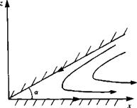
A second approach (inverse) is where the flowfield shape is sought for a given complex potential F. For example, consider the complex potential

F = BY”,a

where В is real. The stream function in polar coordinates is

4х = Вгл/а sin

It can be seen that W = 0 at 0 = 0 and 6 = a, and therefore this potential represents flow in a corner as shown in Fig. 6.7. The complex velocity is

Подпись: FIGURE 6.7 Flow in a corner.
image210

and at the corner Y = 0, the velocity is zero if a < л and infinite if a > л. If a = л/2, the flow can be considered to be either the flow in a right-angle corner or flow against a horizontal wall. This flow is called stagnation point flow and is shown in Fig. 3.6.

SIMPLE EXAMPLES

To evaluate the complex potential of two-dimensional flowfields, we shall apply Eq. (6.13) to the results of some basic flows that were treated ifl Chapter 3.

6.3.1 Uniform Stream and Singular Solutions

The complex potential for the flow of a uniform stream of speed Qx in the x direction is obtained by substituting the results for the velocity potential and stream function into Eq. (6.13) to get

Подпись: (6.15)F = Ф + /Ф = Qx(x + iz) = G»Y

Now, consider the stream to be at an angle a to the x axis and repeat the process. The complex potential becomes

F = Qx(x cos a + z sin a) + iQ^(-x sin a + z cos a)

= Q Jcos a – і sin a)(x + iz) = Q„Ye~ia (6.15a)

This illustrates the general result that the complex potential for one flowfield
can be made to represent the same flowfield rotated counterclockwise by or if У is replaced by Ye~’a.

Consider a source of strength a at the origin. Its complex potential can be obtained similarly and using polar coordinates we get

F = ~(nr + ів) = ~nY (6.16)

2.тг 2<тг

Note that it is easy to demonstrate that for a source at У = Y0 = x0 + tz,,, the complex potential is

F = ^ln(y-y0) (6.16a)

and in general a flowfield can be translated by У0 by replacing У by У – У0 in the complex potential. The complex potential for a vortex with clockwise circulation Г at У = У0 is

Подпись: (6.17)f-Цму-п)

The complex potential of a doublet at the origin whose axis is in the x direction is

Подпись: (6.18)JLi

2л Y

Подпись: F = Подпись: 2л:(У-У0) Подпись: (6.18a)

Using the above rules, the complex potential for a doublet at Y=Y0 with an axis at an angle a to the x direction is given by