Category AERODYNAMICS

The Aerodynamic Loads

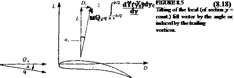
The solution of Eq. (8.16) will provide the spanwise bound circulation distribution Г(у). To obtain the aerodynamic forces, the two-dimensional Kutta-Joukowski theorem will be applied (in the у = const, plane). However, because of the wake-induced velocity, the free-stream vector will be rotated by

image263,image264

a,(y), as shown in Fig. 8.5. This angle can be calculated for a known Г(у) by using Eqs. (8.10) and (8.13):

By assuming that or, is small, then cos a, ~ 1, and sin a, ~ a, and the lift of the wing is given by an integration of the local two-dimensional lift (see Eq. (3.113)) as

гьа

L = pQao Г(у) dy (8.19)

J-ьа

while the drag force, which is created by turning the two-dimensional lift vector by the wake induced flow, becomes

гыг

A = pQ°° ЖуЖу) dy (82°)

■>-ыг

This drag is called induced drag because it is induced by the trailing vortices. This finite wing’s drag is directly related to the lift and will diminish as the wing span increases (b —»°°). Equation (8.20) can also be rewritten in terms of the wake-induced downwash w, :

гЬП

Di = – p w,(y)r(y) dy (8.20a)

■>~ыг

From the engineering point of view, the total drag D of a wing includes the induced drag A and the viscous drag D0:

D = A + D0

For example, the two-dimensional viscous drag of a NACA 0009 section is presented in Fig. 5.19.

The Lifting-Line Model

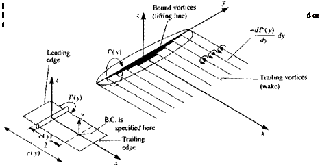
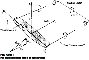
The simplest model that can be suggested to solve this problem is where the chordwise circulation, at any spanwise station, is replaced by a single concentrated vortex. Also, these local vortices of circulation Г(у) will be placed along a single spanwise line. Based on the results of Section 5.5 for the two-dimensional lumped-vortex element, this vortex line will be placed at the wing’s quarter-chord line along the span, – b/2<y <Ы2 (this bound vortex line is assumed to be straight and parallel to the у axis, as shown in Fig. 8.1). The above positioning of the vortex line at the wing’s quarter-chord line effectively satisfies the Kutta condition of Eq. (8.4) as was shown in Section

5.5.

At this point, attention needs to be focused on the vortex theorems requiring that a vortex line cannot start or end abruptly in a fluid (or Eq.

(8.5) ). Therefore, if any change of the vortex line strength yx = dT(y)/dy is introduced, it must be followed by introducing a similar vorticity component in the other direction yy. In other words, the vortex line does not terminate at this point but it changes direction, and its strength remains constant.

The most physical application of these principles is to “shed” these trailing vortices into the flow and create a “wake” such that there will be no force acting on these free vortices Following Section 4.7, this requirement reduces to the condition that the flow along this segment must be parallel to Г (where positive Г is according to the right-hand rule)

q x rwake = 0 (8.6)

The most basic element that will fit these requirements will have the shape of a “horseshoe” vortex (Fig. 8.1), which will have constant “bound vorticity” Г along its quarter-chord line, will turn backward at the wing tips and will continue far behind the wing, and eventually will be closed by the starting vortex. It is assumed here that the flow is steady and therefore the starting vortex segment is far downstream and its influence can be neglected.

A more refined model of the finite wing was first proposed by the German scientist Ludwig Prandtl (see Ref. 5.2) during World War 1 and it uses a large number of such spanwise horseshoe vortices, as illustrated by Fig.

8.2 (the following analysis is in the spirit of this early model). The straight bound vortex T(y) in this case is placed along the у axis and at each spanwise station the leading edge is 1/4 chord ahead of this line and the local trailing edge is 3/4 chord behind the vortex line. Now, let’s examine the integral equation (Eq. (8.3)) for the case of the flat lifting surface, where B-q/Bx =0.

The equation now simply states the boundary condition of Eq. (8.2):

Подпись:

image256

дФ»іп8 | ЭФ wake ^

dz dz

That is, the sum of the normal velocity components induced by the wing tvb = 3<bwing/dz and wake vortices w, = ЗФwake/ dz, plus the normal velocity component of the free-stream flow Q^a must be zero on the wing’s solid boundary:

wb + w, + Q^a = 0 (8.7)

where w is considered to be positive in the +z direction. The subscripts ( )b and ( ), stand for bound (on wing) and induced (by wake) influences, respectively.

The Lifting-Line Model

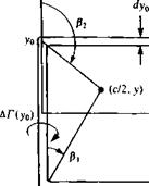
The velocity component wb induced by the lifting line on the section with a chord c(y) can be estimated by using the lumped-vortex model with the downwash calculated at the collocation point which is located at the 3/4 chord. Consider the spanwise component (—y0<y <y0) of a typical horseshoe vortex in Fig. 8.3 with strength ДГ(у0). The downwash Ди^ at the collocation point (c/2, y) due to this segment is given by Eq. (2.69) (see Fig. 2.15, which defines the angles p in this formula) as

-АГ Г У+Уо Уо-У

Алс(у)/2 l_V(c/2)2 + (у +у0)2 /(с/2^ + (уо-у)2

The Lifting-Line Model

The Lifting-Line Model

The result for the complete lifting line (evaluated at y) is obtained by summing the results for all the horseshoe vortices and is


-Г(у)


(8.8)


Note that this is identical to the result obtained by applying a locally two-dimensional lumped-vortex model at each spanwise station, where the downwash wb is measured at the 3/4 chord due to a vortex Г(у) placed at the 1/4 chord position (see inset in the left hand side of Fig. 8.2).

Next, the downwash due to the wing trailing vortices must be evaluated. Since a change in the spanwise circulation Г(у) is allowed, and since no vortex can begin or end in the flow, the local change in this circulation is shed into the wake. Thus, the wake is now constructed from semi-infinite vortex lines with the strength of (dT/dy) dy (Fig. 8.2). Before proceeding with the solution, the velocity induced by a single, semi-infinite trailing vortex line with a strength ДГ = [-dr(y0)/dy] dy0, is evaluated (note that for positive ДГ on the +y side of the wing, negative dT/dy is needed). The right hand side wake vortex line is located at a spanwise location y0, as shown in Fig. 8.3, and the downwash induced by this vortex at the collocation point (c/2, y) is given by the result for a semi-infinite vortex line from Eq. (2.71). Since for a large aspect ratio wing the collocation point is effectively on the у-axis, /3, ~ л/2, /32 ~ л (in Fig. 2.15) and therefore


The Lifting-Line Model

(8.9)


уЬ

image258

-Уо


The Lifting-Line Model

D


FIGURE 8.3

Velocity induced by the segments of a typical horseshoe element.


§


image257image259

which is exactly one-half of the velocity induced by an infinite (two – dimensional) vortex of strength АГ(уо)- With the aid of this equation the normal velocity component induced by the trailing vortices of the wing

becomes.

-ДХ-Уо) ,

1 (ba dy dy°

Подпись: -Ы2 y-y0w‘-t„L —ь – («»>

Dividing Eq. (8.11) by the free-stream speed results in

^Г(уо)

-Г(у)_____ l_ Ґ*

, 4лОО0 L

The Lifting-Line Model

(Note that since the trailing vortices are assumed to lie in the 2=0 plane, their induced spanwise velocity component is zero from the Biot-Savart Law, Eq. (2.68b).) Assuming that the wing aspect ratio is large (b/c(y)»1) has allowed us to treat a spanwise station as a two-dimensional section and to transfer the boundary condition to the local three quarter chord. Substituting Eqs. (8.8) and (8.10) into Eq. (8.7) yields

where the induced downwash angle is (note that w is positive in the positive z direction)

image261(8.13)

Equation (8.12) can be rearranged as

Подпись: (8.12a)ae = a — or,

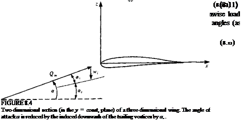
This means that in the case of the finite wing the effective angle of attack of a wing section ae (the angle between the modified free stream velocity q in Fig.

8.4 and the chord) is smaller than the actual geometric angle of attack a by an which is a result of the downwash induced by the wake.

It is possible to generalize the result of this equation by assuming that the two-dimensional section has a local lift slope of m0 and its local effective angle of attack is ae. Now, if camber effects are to be accounted for too, then this angle is measured from the zero-lift angle of the section, such that

с’м-тГЫуМу> <814)

Consequently, Eq. (8.12a) becomes

oce = a – 4- aLo (8.15)

<*Г(Уо)

dy

+ c*(y)- aLo(y) = 0

Подпись: -2Г(у) m0(y)c(y)Q~
Подпись: 1 4 jtQ,
Подпись: У -Уо
image262
Подпись: dy0
Подпись: (8.16)

where is the angle of zero lift due to the section camber (for cambered airfoils, usually au is a negative number). A more general form of Eq. (8.11a) that allows for section camber and wing twist ar(y) is now

In this equation a(y) is the local angle of attack relative to Q« and aLo(y) is the airfoil section zero-lift angle. If it is assumed that these geometrical quantities are known, then Г(у) becomes the unknown in this equation. Also, at the wing tips the pressure difference [or the lift pQS(y = ±6/2)] must reduce to zero:

r(y = ±^) = ° (8-17)

SOLUTIONS

In this chapter, three-dimensional small-disturbance solutions will be derived for some simple cases such as the large aspect ratio wing, the slender pointed wing, and the slender cylindrical body. Flow problems requiring more detailed geometries will be treated in the forthcoming chapters.

8.1 FINITE WING: THE LIFTING-LINE MODEL

The three-dimensional lifting wing problem was formulated in Chapter 4, and it is clear that an analytic solution of the integral equations is difficult. However, it is possible to approximate the lifting properties of a wing by a single lifting line, an approximation that will allow a closed-form solution. In spite of the considerable simplifications in this model it captures the basic features of three-dimensional lifting flows, and predicts the reduction of lift slope and the increase in induced drag with decreasing aspect ratio.

8.1.1 Definition of the Problem

Consider a lifting, thin, finite wing (described in Section 4.5) shown in Fig. 8.1, which is moving at a constant speed in an otherwise undisturbed fluid. The free

Подпись: FIGURE 8.1 Far-field horseshoe model of a finite wing.

stream of speed Qa has a small angle of attack a, relative to the coordinate system which is attached to the wing.

The velocity field for this potential flow problem can be obtained by solving Laplace’s equation for the perturbation potential Ф:

V2<h = 0 (8.1)

Following Section 4.5, the boundary condition requiring no flow across the wing solid surface will be approximated at z = 0, for the case of small angle of attack, by

fWo±).e.(g-„) (8.2)

SOLUTIONS

where r) = T)c(x, y) is the camber surface (placed near the x, у plane) and for simplicity the subscript c is omitted in this chapter. For modeling the lifting surface, a vortex distribution is selected (as formulated in Section 4.5). The unknown vortex distribution yx(x, y), and yy(x, y) (shown in Fig. 4.9) is placed on the wing’s projected area at the z = 0 plane. The resulting integral equation is

A proper (and unique) solution for the vortex distribution will have to fulfill the Kutta condition along the trailing edge, such that the vorticity component parallel to the trailing edge (yTE.) is zero:

Also, since vortex lines do not begin or end in a fluid (Eq. (4.64)), the solution must comply with

Подпись: (8.5)ду*=дУу Эу Bx

THIN AIRFOIL IN GROUND EFFECT

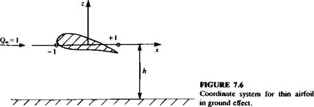
The thin airfoil in ground effect problem will be studied as an example of a perturbation expansion for a case with two small parameters, the standard thin-airfoil parameter (thickness, camber, or angle of attack) and the chord to wall clearance ratio. A thin airfoil is placed in a stream along the x axis (see Fig. 7.6) in the presence of a ground plane located h semichords from the airfoil’s midchord. We will consider a solution linear in thickness, camber, and angle of attack (first-order thin-airfoil theory) for h » 1. It is convenient to use dimensionless variables with lengths scaled by the semichord, speeds by the free stream speed, and the velocity potential by the product of the two. For simplicity, we will drop the bars on the dimensionless variables.

The airfoil boundary condition is transferred to the strip on the x axis with -1 < д: < 1 and the mathematical problem for the perturbation velocity potential becomes

о

II

О

гч

(7.54)

(7.55)

ЭФ,

(7.56)

Equation (7.55) is the airfoil boundary condition from Eqs. (7.10) and (7.13a) and Eq. (7.56) is the ground plane boundary condition. A Kutta condition must be applied at the airfoil trailing edge to complete the problem specification.

The solution is modeled by a distribution of sources of strength a(x) per unit length and vortices of circulation y(x) per unit length along the strip —1 s 1, z = 0 and corresponding image distributions are placed on the strip -1 s* < 1, z = -2A to satisfy Eq. (7.56). The perturbation velocity potential

image254

= 7- f tf(*o){ln i(x – X0f + z2] + In [(x – x0)2 + (z + 2A)2]} dxa 4Jt J_ 1

Подпись: for this flow is Ф + 7- f y(x0)[tan_1 —— tan"1 1 dx0 (7.57)

2^J_i L x-x0 x-Xo-l

To apply the airfoil boundary condition (Eq. (7.55)), we need the limit of the z component of velocity on the singularity strip, which is

Подпись: 2 hx0)2 + 4A2 dX°

+ИгЫ[-^0+(,-17+ л» (7-58)

THIN AIRFOIL IN GROUND EFFECT Подпись: (7.59)

Compare Eqs. (7.55) and (7.58) and equate the terms that exhibit a jump across the strip to get the source strength

which is seen to be the unbounded fluid result. The remaining terms in the boundary condition then become an integral equation for the unknown circulation density y(x). This integral equation is written

Подпись: drcJ y(x0)K(x – x„) dx0 = —21 (х0)Л(х — x0) dx0 + 2л(^а — ~j~j (7-60)

Подпись: where

H(x) – 2 ^ 2

v ’ x2 + 4h2

Подпись: ВД —1

x x2 + 4A2

To solve the integral equation we use an approach due to Keldysh and Lavrentiev (see Plotkin and Kennell7 3 for details) and seek an expansion in 1/A of the following form:

The expansion coefficients are found to be

Hm = (—l)1+m/2 2_(m+1) (7.62a)

Kn = (—1)("+1)/2 2-("+1) (7.626)

when m is even and n is odd and are zero otherwise. Equations (7.61) are substituted into the integral equation (Eq. (7.60)) and terms with like powers of 1/6 are collected. The following system of thin-airfoil-like equations for the unknown yn{x) is obtained:

f ^^-dx0=- 2І H^^J1 (xa){x – x0)n~l dx0 J-iX—Xq J_ і ax

rl n — 1

– 2 Km(x-Xo)mYn-m-i{x0)dx0=fn(x) (7.636)

j-l m= 0

The solution to Eqs. (7.63) that satisfies the Kutta condition is obtained with the help of Eq. (7.19) as

For n = 0, the unbounded fluid result is recovered

Let us find the first term in the expansions for the thickness, camber, and angle of attack problems separately. Note that each expansion has either all odd or all even terms so that the terms we neglect are two orders smaller than the ones we keep. Since the thickness and camber problems require the choice of a particular airfoil to proceed, let us begin with the angle of attack problem.

The expansion for the circulation density has terms for n = 0, 2, 4,. . . and for n = 2 the function on the right-hand side of the integral equation (Eq. (7.636)) is

f2 = -2K1a{ J^—^(x-x0)dx0 1 + x0

(l-*o)(*-*o) ла 1ч

Vi-4 +

THIN AIRFOIL IN GROUND EFFECT

_a j 1-х f1 11 +x0x0+l/2 а /Г

2л Vl +x J_! VI – x0 x0-x 0 2V1

(Note that


Ґ jl+Xof (x0) J г1 1+ДСо /Ы,

J_,*■

is introduced so that the integrals in Appendix A can be used).

As an example to illustrate the camber effect, choose the parabolic arc camberline given by

r,, = P( 1-х2)

The expansion for the circulation density has terms for n = 0, 2, 4,… and the unbounded fluid result (n = 0) is found from Eq. (7.65) as

УоСО = – — f *oЛїї–*0 dX°- = 4/3Vl—*2 (7.68)

л Vl+xJ-j VI-XqX-Xo

For n = 2, the function on the right-hand side of the integral equation (Eq. (7.636)) is

/2 = 0* J (*-*o)Vl-Xodio = – p (7.69)

and the solution for the circulation density for n = 2 is found from Eq. (7.64) as

Подпись: (7.70)*0 dx0 – p

X0X0-X 2

As an example to illustrate the thickness effect, consider the approximate Joukowski airfoil with thickness function given by

= Ti(l — *)Vl – x2

The expansion for the circulation density has terms for n = 3, 5,… and for n = 3 the function on the right-hand side of the integral equation (Eq. (7.636)) is

r _ г j f1 (2xl ~ *0 “ 1)(* – xQ)2 ‘■"ТІ, — 4

-і——- *.= – y(< + J) (7.71)

and the solution for the circulation density for n = 3 is found from Eq. (7.64)

ті /і – x f1 , 1. /і + Xo dx0 t, / 1-х , ,

Vr^ J_, +—j Vttj+» <772>

The lift coefficient for the airfoil is found from the nondimensional circulation density as

The lift coefficients for the separate angle of attack, camber, and thickness effects which include the first term in the ground-effect expansion are obtained by substituting Eqs. (7.67), (7.70), and (7.72) into Eq. (7.73) to get

Angle of attack:

С, = 2ла[ + th~2 + 0(/t~4)]

(7.74a)

Parabolic arc camber:

Ci = 7T/S[1 -h~2+ 0(A~4)]

(7.746)

Joukowski (thickness):

Q=_l6 h~3 + 0{~h~5)

(7.74c)

Note that the first term in Eq. (7.74a) is identical to the result obtained in Section 5.5 using a single-element lumped-vortex model (in Eq. (7.74a) remember that h is normalized by the semichord). Additional terms for the angle of attack and Joukowski solutions may be found in Plotkin and Kennell.73 It is seen that for these examples and for the assumptions connected with the expansions the ground plane increases the lift due to angle of attack and causes a decrease in lift due to the airfoil thickness and camber.

MATCHED ASYMPTOTIC EXPANSIONS

We will use the method of matched asymptotic expansions to obtain a solution that is uniformly valid over the airfoil surface. Our results will be presented essentially in outline form and further details are available in Van Dyke.5 3 The success of the method is predicated on the observation that the two solutions complement each other and it is expected that in the limits of their applicability they approach each other (the limit of the thin-airfoil solution as the leading edge is approached should somehow be equivalent to the limit of the local solution as the distance from the leading edge is increased). The local solution is called the inner solution and the thin-airfoil solution is called the outer solution.

The formal task of matching the inner and outer solutions is achieved through the asymptotic matching principle (Van Dyke,5 3 p. 90):

The m-term inner expansion of the л-term outer expansion = the л-term outer expansion of the лі-term inner expansion

Outer variables are scaled with the airfoil chord and inner variables are scaled with the nose radius; m and n are integers, not necessarily equal. The definition of the m-term inner expansion of the n-term outer expansion is expressed in the following sequence of steps:

1. Re-write the л-term outer expansion in inner variables.

2. Expand in an asymptotic series for small є (or r).

3. Keep m terms.

We will apply the above matching technique to the surface speed for the flow past a symmetric Joukowski airfoil at zero angle of attack. The three-term (я = 3) outer expansion in dimensionless coordinates is given in Eq. (7.37) as

£-l + rl(l-2f)-|£j<l + 2«)’ (7.47)

In terms of s = 2s/с = x + 1, Eq. (7.47) becomes

q = G-[ 1 + *i(3 – 2s) ~ (2s – l)2] (7.47a)

Подпись: (7.48)

To second order in the thickness x, the airfoil can be represented locally by the parabola so that the two-term (m = 2) inner expansion is given in Eq. (7.46) as

The Joukowski airfoil (Eq. (7.30)) becomes

z = ± r,(2 – s)y/2s – s2 (7.49)

and as s —»0 we get the parabola z = ±V8t? s. From Eq. (7.40), the parabola is z = ±V4sr/c. The nose radius is therefore r = 2cx.

Let us now do the matching for q.

Подпись: V Подпись: s + 2r2 Подпись: (7.50a)
image252

Two term inner expansion (already in outer variables):

expanded for small

Подпись:F(l-|) + 0(rt)

Three-term outer expansion:

F(l-|) (7.50c)

Three-term outer expansion:

e»[l + T1(3-2f)-^^(2s-l)2] (7.51a)

rewritten in inner variables (note that S = s/tf)

Q 1 + r,(3 -2r25) ~Y~^(2riS – l)2] (7.51b)

expanded for small r,

еф + З^-^ + О^2) (7.51c)

Two-term inner expansion:

Q”[1_J + 3Tl] = Є“[1 + ЗТі_1І] (7.51d)

The matching is complete when we equate the results for q from Eqs. (7.50c) and (7.51d) to get V — Q^(l + 3tj). The local solution therefore experiences a free-stream speed that is larger than the actual one.

The final step in the analysis is to combine the inner and outer solutions to obtain a solution valid over the complete airfoil surface. At best the solution will be as accurate as either the inner or outer expansions in their regions of applicability. The combined solution is called a composite expansion (Van

Dyke,5 3 pp. 94-97) and we will use the additive composite

f(m, n) = f(m) + fin) _ Ш = 2, П —3 (7.52)

The additive composite expansion is the sum of the inner and outer expansions minus the part they have in common (i refers to inner and о refers to outer). This common part, the last term in Eq. (7.52), is obtained during the matching process and is given in Eq. (7.50c). Our result is

J„-d + 3l’)Vl + 2tf 1 1 ‘ tl<3_ 2t)“ 2 Ї <b ‘>

І + Зг.-Ь]

(7.53)

After some manipulations this result becomes

Gm-(1 + 3Ti)Vs + 2t? ^’2(^ 3)

(7.53«)

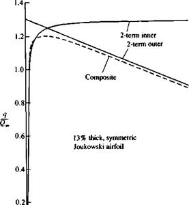
The important feature to note in the solution is that the singular part of the thin-airfoil result in the neighborhood of the leading edge has been removed. (Figure 7.5 compares the inner, outer and composite expansions for a particular value of the thickness.)

image253

0І_______ I_______ I_______ I_______ I

-0.5 – 0.25 0 0.25 0.5

FIGURE 7.5

Подпись:Inner, outer, and composite ex­pansions for the 13 percent thick symmetric Joukowski airfoil.

LEADING-EDGE SOLUTION

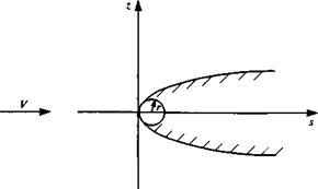
The second-order solution of Eq. (7.37) shows that the perturbation expansion for the thin airfoil breaks down in the neighborhood of the round leading edge in a region whose extent is measured by the leading-edge or nose radius of the airfoil r (r is the radius of curvature at the leading edge). Also, r is 0(e2). To illustrate the correct local solution in the neighborhood of the leading edge, let us consider a symmetric airfoil at zero angle of attack. Introduce the coordinate s = x + c/2, which is measured from the leading edge (Fig. 7.3). Many symmetric low-speed airfoil sections are analytic in the leading-edge region and their surfaces can be described by

z = ±T0sm ± 7[s3/2 ± • • • (7.38)

where T0, 71, . . . are constants.

For small values of s [or for s = 0(e2)], the surface is given by the first

term

z = ±VT%s (7.39)

which is seen to be identical to the equation of a semi-infinite parabola, which can also be given by

z = ±V2ra (7.40)

The local solution then is the symmetric flow past this parabola whose

geometry is shown in Fig. 7.3 and since this solution is not valid in the far field, let us for the moment denote the stream speed as V. The method of conformal mapping will be used to obtain the surface speed on the parabola. Consider the mapping

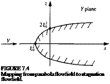
Y=-f2=ti2-?-2i£r, (7.41)

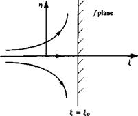
where Y = x + iz and / = £ + ir). Then it can be seen that the curve f = £0 in

the / plane maps into the parabola

Подпись: FIGURE 73 Symmetric flow past semi- infinite parabola.
image248

z = ±V5fW+Ш) (7.42)

Подпись: FIGURE 7.4 Mapping from parabola flowfield to stagnation flowfield.
image250

in the Y plane and the corresponding flowfields in the two planes are shown in Fig. 7.4.

The flow in the/plane is seen to be stagnation point flow against the wall § = and its complex potential is

F = — V(f — §0)2 (7-43)

LEADING-EDGE SOLUTION Подпись: -2V(f - g0) -2/ Подпись: Virj do + Щ) Подпись: (7.44)

The constant V has been chosen to provide the correct far field solution in the parabola or physical plane. On the surface we have / = іт/, § = §0, and the complex velocity becomes

Now, rj = V* + £o and if we introduce s = x + §o> the surface speed on the parabola is

Подпись: Я V image251(7.45)

Note that the surface speed at any point is just the projection of the free-stream speed onto the tangent.

Since the nose radius of the parabola is r = 2§o (Eq. (7.42) yields z = ±V4fo$), the desired local surface speed for the airfoil becomes

The corresponding local solution for the airfoil problem with camber and angle of attack is given in Van Dyke.7 2 We therefore have available two incomplete solutions to the problem we set out to solve at the beginning of the chapter. The thin-airfoil solution has been obtained correct to second order but it is not correct in the neighborhood of the leading edge. The local solution is exact in
the neighborhood of the leading edge but does not describe the flow in the far field and it also contains an undetermined constant.

SECOND-ORDER SOLUTION

SECOND-ORDER SOLUTION Подпись: (7.20a) (7.20b)

Consider the second-order solution. Define fictitious thickness and camber functions as

This puts the second-order problem in the same form as the first-order one at zero angle of attack (see boundary conditions in Eqs. (7.14)-(7.16)) and the

SECOND-ORDER SOLUTION Подпись: (7.21) (7.22) (7.23)

solution can be written as

and the z component is obtained from the boundary conditions (Eqs. (7.15) and (7.16)).

The surface speed on the airfoil is the magnitude of the velocity and to obtain its value at any order the velocity components at that order are substituted into

q = Vm2 + w2 (7.24)

the expansion for the square root

Подпись:(l+x)1/2 = 1 + — — +•• • for ДГ < 1

2 о

is used, the results are evaluated in terms of values on the chordline, and only terms up to the desired order are kept. The expressions for the surface speed correct to first and second order are derived as follows. On the surface, to second order,

, , 2 Гл/, Л ЗФ[ ЭФ212 Г ЭФ! ЭФ212

q=u+w =|q„(i-t)+_ + _J +^„a + _ + _j

If the results are evaluated at z = 0 and terms up to second order are kept,

Подпись: Э ЭФ1 dz Эхql = Ql + 2G»(u1T ± UiL + u2T ± u2L) + 2Q„r)

„ ЭФ, Г 9Фі І2

+ (uir ± ulLf + 26»*— (x, 0±) + 1^— (x, 0±)j

Note that

^Фі д ЗФі Э

SECOND-ORDER SOLUTION

0±) – 5-5*1<*•0±) – 0-5 – °-’1′

+ 2a(r)’ — a) + 2г)г)" + (ту’ – a)2

= 1 + ^- (Mlt ± Mil + u2T ± u2L) + (U’T – a2 + (ту’)2 + 2туту"

With the use of Eq. (7.24a) we get q2 If 2

Подпись: -Q. (U1T І UlL)2 ~q~ = 1 + 2 Yq~ (UlT ^ UlL Urr ^ uil)

Подпись: ~a1 + (v')2 + (“ir ± UIL)

Therefore,

Подпись: (7.25a)Q , Ut Mi#

— = і + —± —

CL Є. Є»

m±";>2-t ir25b)

The surface pressure coefficient (correct to second order) is obtained from Bernoulli’s equation as follows:

C =1-^

p Ql

SECOND-ORDER SOLUTION

Compare the expression for ql/Ql above to the expression for q2IQ^ in Eq. (7.25b) to observe that

and therefore

Подпись: (7.26)Подпись: (7.27)Qoo / VQoo Q,

The airfoil lift coefficient can then be determined from

1 (ca

C, = – [Cp(x, 0-) – Cp(x, 0+)] dx

C J-c/2

and with the use of Eqs. (7.25b) and (7.26) is

Подпись:4 ,U" Mq21L + 7P+ Wc + VcV’!+ Vcnl) dx (7.28)

SECOND-ORDER SOLUTION Подпись: (7.29)
image246

To illustrate the results of second-order thin-airfoil theory, consider a symmetric airfoil at angle of attack and the surface speed is to be calculated. The following thickness function represents a symmetric Joukowski airfoil to second order in thickness ratio (see Van Dyke,5 3 p. 54):

where t, = 4т/ЗУЗ and r is the thickness ratio. To evaluate the Cauchy principal value integrals appearing in the equations for the x component of velocity at various orders, it will be advantageous to use Appendix A, which is
reproduced from Ref. 7.2. Therefore, lengths must be scaled by half the chord length to obtain the limits of integration from -1 to +1. Introduce the nondimensional coordinate x = x/(c/2). The nondimensional thickness func­tion for the Joukowski airfoil becomes

The nondimensional versions of Eqs. (7.17) and (7.19) for this symmetric airfoil become

“ir 1 f1 df), dx о n = If – (*o) – – Qoо it J—і dx x – x0

(7.31a)

“XL / 1-Х

Qa “Vl+i

(7.31ft)

The slope of the nondimensional thickness function is

^~-‘= т,(1 – jc2)-U2(-1 —x + 2×2)

(7.32)

and the first-order x component of velocity becomes

е_-1 + т,<1

(7.33)

The nondimensional thickness and camber functions at second order (Eqs. (7.20a, ft)) are then

Vh = TiVl – Xі (1 – 3x + 2×2)

(7.34a)

»7c2=*1<*(1-*)2

(7.34ft)

and their nondimensional derivatives are

(7.35a)

(7.35ft)

The second-order result for the x component of velocity is obtained from the nondimensional version of Eqs. (7.21), (7.22), and (7.23) and is

The second-order result for the surface speed from Eq. (7.25b) is obtained with some manipulation as

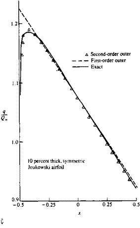
FIGURE 7.2

Подпись: c Surface speed results for 10 per­cent thick symmetric Joukowski airfoil.

The first – and second-order surface speeds for a 10 percent thick Joukowski airfoil are shown in Fig. 7.2 and compared with the exact result from Chapter 6 for the case with zero angle of attack. It is noted that the first-order thickness solution is not singular at the leading edge but that the leading-edge stagnation point and the acceleration region following it are not predicted by the theory. This is not surprising since the approximations of the theory are invalid in the neighborhood of a stagnation point and round edge. The deceleration region over the rear of the airfoil appears to be predicted well by the theory. The second-order surface speed improves the comparison with the exact results over most of the foil (including the maximum speed) but is now singular at the leading edge. If we were to continue to higher order, the solution would become more and more singular at the leading edge and the thin-airfoil theory is not able to predict the correct behavior in this region.

THIN-AIRFOIL PROBLEM

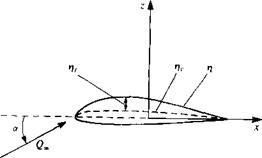
Consider the two-dimensional airfoil problem as a special case of the three-dimensional wing problem of Chapter 4. The dependent variables are now functions of x and z and both the upper and lower airfoil surfaces are given by

f(x, z) = z-tj(x) = 0 -?£x£? (7.1)

Note that the origin is at midchord and that the airfoil chord is c (Fig. 7.1). This choice of the origin is made for convenience in the evaluation of the Cauchy principal value integrals that will appear in the example problems.

The perturbation velocity potential Ф is defined in Section 4.2 by

Ф* = Ф + Ф„ (7.2)

where

Фоо = Uv, x + Wxz = xQ„ cos a + zQm sin a (7.3)

The exact airfoil boundary condition is the two-dimensional version of Eq. (4.12):

Подпись: (7.4)dn/дФ „ ЭФ л.

— (-т – + 6» cos a + — + sin a = 0 on z = n

ax dx / dz

with f/oc = Q, cos or and W„ = Qx sin a. The small-disturbance approximations and limitations on the geometry introduced in Chapter 4 apply and it is assumed that the order of magnitude of the airfoil thickness ratio, camber ratio, and angle of attack can all be represented by the small parameter €.

Let us consider the following expansion for the perturbation velocity potential,

Ф = Фі + Ф2 + Фз + • ■ • (7.5)

image241FIGURE 7.1

Coordinate system for airfoil problem.

Ф, = 0(еі) / = 1,2,3,… (7.6)

and the order symbol O(e) is defined by

g(e) = 0(e) as e—»0 if lim-—-<» (7.7)

e—о є

In this chapter we will carry the analysis through to second order to illustrate the method. Terms to 0(e2) will be kept and therefore the components of the free stream flow are written as

t/»=G«cosa = Q„[l-y+0(a4)] (7.8e)

Ж»= 6» sin a = Qx[a + 0(ar3)] (7.8b)

The boundary condition will be transferred to the chord line as in Eq. (4.16) and the complete boundary condition with the above substitutions becomes

dn Г ЭФ, , 1 ЭФ,

“ ~dx LG”+~aT(JC’0±)J+ Q°°a +~эГ0±)

+ n^1(JC.0±) + ^?(-t, °±) = ° (7.9)

where the ± refers to the upper and lower surfaces. For this equation to be valid for all values of the perturbation parameter e, the terms of the same order (e, є2) must individually be zero. To show this, divide the equation by є and take the limit as є goes to zero. Then all of the terms of O(e) must be zero. Now, subtract these terms from the original equation and repeat the process. This shows that all of the terms of 0(e2) must be zero.

The boundary conditions for the first – and second-order problems then become

0(€):

ЭФ, dn

-^(x, 0±) = Q„-l-Q„a dz dx

(7.10)

0(e2):

ЭФ-, dn ЭФ, Э2Ф,

а>0±>*Лг>0±)-’’Э2>’0±)

(7.11)

Подпись: ЭФ2 dz Подпись: ЭФ, ,^(,,0±) Подпись: (7.12)

If Laplace’s equation for Ф, is used in the second-order condition, it becomes

At this point it is noted that the first-order boundary condition is the one that was used in the thin-airfoil treatment in Chapter 5. Now let us separate the problems at each order into a nonlifting (symmetric or thickness) problem and a lifting (camber and angle of attack) problem and introduce the camber and

ri = r}c±V,

Подпись:Ф] = Фі/. + Фіг Ф2 = Фгх. + Фгт

Note that the lifting potentials (Ф^, Ф2L) are antisymmetric in z and the nonlifting potentials (Фіг, Ф2г) are symmetric in z. Consequently, the z component of velocity w is continuous across the chord for the lifting problems and discontinuous for the nonlifting problems.

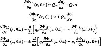
With the above definitions, Eqs. (7.10-7.12) become

Подпись: (7.14ft)Подпись: (7.14a)image242(7.15)

(7.16)

The complete mathematical problems that accompany the above bound­ary conditions (Eqs. (7.14a, ft), (7.15) and (7.16)) include Laplace’s equation for each velocity potential and a velocity field that decays to zero at infinity. A Kutta condition must be applied in the lifting problems and the nonlifting problems have zero circulation.

The solutions to the above mathematical problems can be obtained with the use of the theory of singular integral equations (see Newman,71 Section 5.7). The first-order tangential velocity component is

image243

image244

(7.17)

(7.18)

for the lifting problem. A source distribution for Ф1г also leads to Eq. (7.17) (see Eq. 5.15). A vortex distribution solution for Ф1£. leads to an integral equation for у (Eq. 5.39) and the solution to this integral equation is given in Eq. (7.18) where y = 2u1L.

The nonunique solution (of Eq. (5.39)) with arbitrary circulation is given because for another application the solution with zero circulation will be needed. If the Kutta condition is applied, then uu,(c/2) = 0, and using (Eq.

+ (719)

The x component of velocity on the airfoil is then given by и = + uir ± uu

and the z component is obtained from the boundary conditions (Eq. (7.14a, b)).

PERTURBATION METHODS

For the small-disturbance solution techniques that are treated in this book, approximations to the exact mathematical problem formulation are made to facilitate the determination of a solution. Since for incompressible and irrotational flow the governing partial differential equation is linear, the approximations are made to the body boundary condition. For example, for the three-dimensional wing in Chapter 4, only terms linear in thickness, camber, and angle of attack are kept and the boundary condition is transferred to the x-y plane. The solution technique is therefore a “first-order” thin-wing theory.

The small-disturbance methods developed here can be thought of as providing the first term in a perturbation series expansion of the solution to the exact mathematical problem and terms that were neglected in determining the first term will come into play in the solution for the following terms. In this book we will follow the lead of Van Dyke5 3 and use the thin-airfoil problem as the vehicle for the presentation of the ideas and some of the details of perturbation methods and their applicability to aerodynamics. First, the thin-airfoil solution will be introduced as the first term in a small-disturbance expansion and the mathematical problem for the next term will be derived. An example of a second-order solution will be presented and the failure of the expansion in the leading-edge region will be noted. A local solution applicable
in the leading-edge region will be obtained and the method of matched asymptotic expansions will be used to provide a solution valid for the complete airfoil. Finally, the thin airfoil in ground effect will be studied to illustrate an expansion within an expansion.

METHOD OF IMAGES

Since the solution for the flow past bodies of aerodynamic interest can be represented by suitable distributions of singular solutions to Laplace’s equa­tion, it is important to study the representation of these singular solutions in the presence of additional boundaries, mainly straight, to be able to deal with ground planes and wind-tunnel walls, etc.

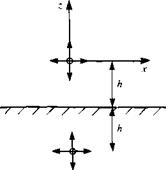
As an example, consider a two-dimensional source of strength a a distance h from a plane wall as shown in Fig. 6.20. Introduce a cartesian coordinate system whose origin is at the source and whose x axis is parallel to the wall. In the absence of the wall, the velocity potential of the source is

Ф = ■£- In Vx2 + z2 (6.76)

2 л

Since we would expect that the only singularity in the flow field is due to

Подпись: FIGURE 6.20 Image of source in plane wall.
image232

the source, we look for a solution of the form

Ф = — Іп^^+^ + Ф, (6-77)

2 л

METHOD OF IMAGES Подпись: (6.78)

where Ф, satisfies Laplace’s equation, has no singularities for z > – A, decays at infinity, and exactly cancels the normal component of velocity at the wall due to the source so that the wall boundary condition is satisfied. The boundary condition on Ф/ is therefore

From symmetry considerations, an “image” source at (0, -2A) is investigated as a possible solution. Its velocity potential is

Ф/ = In V*2 + (2 + 2A)2 (6.79)

2k

and substitution into the boundary condition at the wall shows that it is satisfied. Similar image solutions for a doublet and a vortex are shown in Fig. 6.21. The complex potentials for the original singularities plus their images are

ІГ ІГ

Подпись: (6.82)Подпись: F(Y) =

Подпись: F(Y) = -
Подпись: 2nY
Подпись: JL 1 еі(2л-а) 2n(Y + 2ih)
Подпись: (6.81)
METHOD OF IMAGES

Подпись: (6.80)

Подпись: Source:
Подпись: F(y) = ^lnY + ^ln(Y + 2l7°

— In F – — ln(F + 2ift) 2л 2л

Next consider a source placed midway between two parallel walls a distance h apart. An image source at (0, h) will satisfy the boundary condition on the upper wall but now both the original source and this image source must be canceled at the lower wall to satisfy the boundary condition there. Images at (0, – ft) and (0, -2A) will take care of the lower wall but now two more images are needed for the upper wall and the process will continue until the complete image system plus the original source consists of an infinite stack of sources a distance ft apart as shown in Fig. 6.22. The complex potential for this source stack is

F(Y) = [In Y + In (F – ift) + In (F + ift) + In (F – 2ift) + In (F + 2ih) + • • •] 2 л

(6.83)

Подпись: In (F — inh) + In (F + ink) = In n2h2 + In image233

Each pair of images can be combined as

FIGURE 6.22

Image of source midway between parallel walls.

and if the constant terms are neglected, the complex potential becomes

^

The use of the following identity from Gradshteyn and Ryzhik (Ref. 6.5, p. 37),

sinh A = А П (l + рУ (6.85)

leads to the closed-form solution for the complex potential as

F( У) = ^ In sinh ~~ (6.86)

2 71 H

For a clockwise vortex of circulation Г between parallel walls, an application of the iterative image procedure previously used for the source leads to the solution shown in Fig. 6.23, which consists of a stack of clockwise vortices at Y = 0, ±2h, ±4h, . . . and a stack of counterclockwise vortices at ±h, ±3h, ±5h,…. From before, the complex potential for the clockwise stack is

(6.87)

The use of another identity from Gradshteyn and Ryzhik,

Подпись:Подпись: 4A2 (2k + )2n2 image234"(6.88)

FIGURE 6.23

Image of clockwise vortex midway be­tween parallel walls.

results in the following complex potential for the vortex between walls:

F( Y) = [In sinh ~ – In cosh ^7-] = In tanh ~ (6.89)

y 2л і 2h 2h 2л 2h

We have considered images of the singular solutions in a plane wall (for ground-effect applications) and between parallel walls (for wind-tunnel ap­plications). Another possible application is the interaction of an airfoil with its wake or the wake of another airfoil (for unsteady motion) and since we have shown that an airfoil geometry can be transformed through conformal mapping into a circle, the image system for a singular solution in the presence of a circle will be studied.

The circle theorem due to Milne-Thomson6 6 states that if the complex potential F,( Y) represents a flow without singularities for Y<a, then

F(Y) = F,(Y) + fl(^) (6.90)

represents the same flow at infinity with a circular cylinder of radius a at the origin. The function Ft(Y) is defined in the following way. “If F^x) is a function that takes complex values for real values of x, Fx(x) is the function that takes the corresponding conjugate complex values for the same real values of x, and FX(Y) is obtained by writing Y instead of x."

Consider the simple example where Ft(Y) = UY, a uniform stream in the x direction. FX(Y) is seen to be also UY and therefore the flow of the uniform stream with a circle at the origin is given as

a2

F(Y) = UY+U~ (6.91)

which is simply the stream plus doublet solution previously derived. Now let

F1(Y) = ^|n(Y-Yo) (6.92)

which is the complex potential for a source of strength a at Y = Y0. FX(Y) is

Fx(Y) = ~n(Y~Y0) (6.93)

and the complex potential for a source outside a circular cylinder becomes (Eq. (6.90))

F(Y) = ~ [in (Y — Y,) +ln (^p — 1^)] (6.94)

The following manipulation will put the above result in the form of a recognizable image system:

F(y)=Shy-y»)+in(7-f»)]

‘s[ln<y^w + ,"l+,n(y-0-1)]

= ^ [In (Y – Y0)] – In Y + In (y – j-j (6.95)

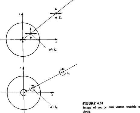
where the constant terms have been neglected. It can be seen that the solution consists of the original source, an image source of the same strength at the image point, and a sink of the same strength at the origin. These three singularities line up along the same radial line from the origin, as can be seen by writing the location of the image point as

fl2_fl2Yo / a2

Y0 Y0Y0 |Y0|2/ 0

For a clockwise vortex of circulation Г at Y = Y0 outside a circle, the image system consists of a counterclockwise image at the same image point as for the source and a clockwise vortex at the origin. Both of these image systems are illustrated in Fig. 6.24.

image235

METHOD OF IMAGES Подпись: (6.96)

As a final example, take

Подпись: then METHOD OF IMAGES Подпись: (6.97)

which is the complex potential for a doublet of strength /л at Y = У0 whose axis is at an angle a to the x direction. With the use of the result that

image236 Подпись: (6.98)

and the complex potential for the doublet outside of a circle becomes

image237 Подпись: (6.98а)

The following manipulation will put the result in the form of a recognizable image system:

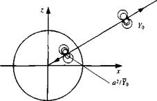
where the constant term has been neglected. The image of the doublet in a circle is therefore seen to be another doublet inside the circle at the image

image238

FIGURE 6.25

Image of radial doublet outside a circle.

image239

point previously derived for the source but with a reduced strength

For the special case of a doublet pointing outward along the radial line from the origin, arg Y0= a, and the complex potential becomes

image240(6.99)

This doublet plus its image are shown in Fig. 6.25.