Category AERODYNAMICS

THE AERODYNAMIC LOADS

Solution of the aforementioned problems (e. g., the thickness or lifting problems) results in the velocity field. In order to obtain the aerodynamic loads the pressures need to be resolved by using the Bernoulli equation (Eq.

(4.4) ). Also, the aerodynamic coefficients can be derived either in the wing or in the flow coordinate system. In this case of small disturbance flow over wings, traditionally, the wing coordinates are selected as shown in Fig. 4.10. The velocity at any point in the field is then a combination of the free-stream velocity and the perturbation velocity

q=^<2oocosar + —, —, — – fQooSina’j (4.51)

Подпись: Qimage130FIGURE 4.10

Wing-attached coordinate system.

Substituting q into the Bernoulli equation (Eq. (4.4)) and taking into account the small-disturbance assumptions (Eqs. (4.13) and (4.14), and a« 1) yields

p»-p = ^0?2-G«)

image131

THE AERODYNAMIC LOADS image132 Подпись: (4.52)
image133

— 0» cos2 a + 2Qn cos a— + 2 L dx

Подпись: e£Z£==1. p pQl Подпись: „ ЭФ/Эх Q~ Подпись: (4.53)
image134

The pressure coefficient Cp can be defined as

Note that at a stagnation point q = 0 and Cp = 1. In the undisturbed flow q = Q„ and Cp = 0. The aerodynamic loads, then, can be calculated by integrating the pressures over the wing surface:

F= — I pndS (4.54)

■’wing

When the surface shape is given as in Eq. (4.6) then the normal to the surface is given by Eq. (4.7), which with the small-disturbance approximation

becomes:

J_ (_dV _ /_dq _3q A

|VF| dx ’ dy ’ / дх’ ду/

Consequently the components of the force F can be defined as axial, side, and normal force

p f / driu дур

x LJPu Эх Pl Эх/

| dx dy

(4.55)

f ( Эг)и dr) A

1 dx dy

(4.56)

F2= I (p,-pu)dxdy

■’wing

(4.57)

Here the subscripts и and / represent the upper and lower wing surfaces, respectively. Aerodynamicists frequently refer to the forces in the free-stream coordinates (Fig. 4.10), and therefore these forces must be transformed accordingly. For the small-disturbance case the angle of attack is small and therefore the lift and drag forces are

D = Fx cos a + Fz sin a L = —Fx sin a + Fz cos a ~ Fz

Note that the evaluation of drag by integrating the pressure distribution is considered to be less accurate than the above formulation for the lift.

In the case when the wing is assumed to be thin, the pressure difference across the wing Ap is evaluated (positive Ap is in the +z direction) as

ЭФ г ЭФ ]

Ар = Pt ~ Ри = Р» – PG-(*> У> 0-) – [p. о – pG~ (X, y, 0+) J

г яф дф и

= рЯ~[-^(х, У>в+)–^(Х’У,0-) (4-58)

If the singularity distribution is assumed to be placed on the x—y plane then the pressure difference becomes:

Source distribution. Because of symmetry,

ЭФ ЭФ

and

ГЭФ ЭФ 1

Ap = pG»[— (*> У> 0+) _ у (x> У> °+)J = 0 (4.59a)

Подпись: ЭФ dx

THE AERODYNAMIC LOADS

Doublet distribution. In this case

and the pressure difference becomes

Подпись: (4.59 b)Ap = pG~ ^ АФ(дс, у) = – pQo*

where АФ = Фи — Ф/.

Vortex distribution. For the vortex distribution on the x-y plane the pressure jump can be modeled with a vortex distribution yy{x, y) which points in the у direction , such that

— (x, y, 0±) = ± 2Yy(x, y)

therefore, the pressure difference becomes

Ap = pG« АФ(дг, у) = pQ„Yy(x, у) (4.59c)

The aerodynamic moment can be derived in a similar manner and as an example the pitching moment about the у axis for a wing placed at the z = 0

plane is

Mx=o=J Apxdxdy (4.60)

•’wing

Usually, the aerodynamic loads are presented in a nondimensional form. In the case of the force coefficients where F is either lift, drag, or side force the the corresponding coefficients will have the form

Подпись:F

ipQls

THE AERODYNAMIC LOADS Подпись: (4.62)

where 5 is a reference area (wing planform area for wings). Similarly the nondimensional moment coefficient becomes

Here, again M can be a moment about any arbitrary axis and b is a reference moment arm (e. g., wing span).

ZERO THICKNESS CAMBERED WING AT ANGLE OF ATTACK—LIFTING SURFACES

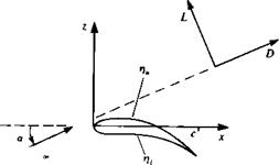
Here we shall solve the two linear problems of angle of attack and camber together (Fig. 4.7). The problem to be solved is

V2<& = 0 (4.29)

with the boundary condition requiring no how across the surface (evaluated at z = 0) as

(4.41)

This problem is antisymmetric with respect to the z direction and can be

Подпись: FIGURE 4.7 Nomenclature used for the definition of the thin, lifting-wing problem.
image125

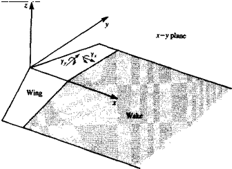
solved by a doublet distribution or by a vortex distribution. These basic singularity elements are solutions to Eq. (4.29) and fulfill the boundary condition (Eq. (4.2)) at infinity. As mentioned in Section 2.9, vortex lines cannot begin and terminate in the fluid. This means that if the lifting problem is to be modeled with vortex elements they cannot be terminated at the wing and must be shed into the flow. In order to riot generate force in the fluid, these free vortex elements must be parallel to the local flow direction, at any point on the wake. (This observation is based on the vector product Q«, x Г in Eq. (3.113).)

In the following section two methods of representing lifting problems by a doublet or vortex distribution are presented. Also, as a consequence of the small-disturbance approximation, the wake is taken to be planar and placed on the z = 0 plane.

ZERO THICKNESS CAMBERED WING AT ANGLE OF ATTACK—LIFTING SURFACES Подпись: (4.42)

DOUBLET DISTRIBUTION. To establish the lifting surface equation in terms of doublets the various directional derivatives of the term 1/r in the basic doublet solution have to be examined (see Section 3.5). The most suitable differentiation is with respect to z, which results in doublets pointing in the z direction that create a pressure jump in this direction. Consequently, this antisymmetric point element placed at (x0, y0, Zo) will be used:

The potential at an arbitrary point (x, y, z) due to these elements distributed over the wing and its wake, as shown in Fig. 4.8 (zq = 0), is

Ф (x, y,z) = — _

*rJt Jwing+wake IKX *o)

The velocity is obtained by differentiating Eq. (4.43) and letting z -*• 0 on the wing. The limit for the tangential velocity components was derived in

Section 3.14, whereas the limit process for the normal velocity component is more elaborate (see Ashley and Landahl,41 p. 149).

Подпись: 1 dfi 2dxЭФ

u(x, y, 0±) = —

Подпись:Подпись: v(x, y, 0±) =Подпись: M*o, Уо) ^wing+wake ^ image126

image127

2 ay

(4.44)

To construct the integral equation for the unknown ц(х, у), substitute Eq.

(4.44) into the left-hand side of Eq. (4.41):

J_ f M*o> Уо) L,_____________ (-«–to)_______ 1 . .

43Ї Jwing+wake (У – Уо)* L V(* – X0f + (У~ Уо)* + Z2 ° У0

"«-(£—) <445>

The strong singularity at у – y0 in the integrals in Eqs. (4.44) and (4.45) is discussed in Appendix C.

VORTEX DISTRIBUTION. According to this model, vortex line distributions will be used over the wing and the wake, as in the case of the doublet

ZERO THICKNESS CAMBERED WING AT ANGLE OF ATTACK—LIFTING SURFACES Подпись: (2.68b)

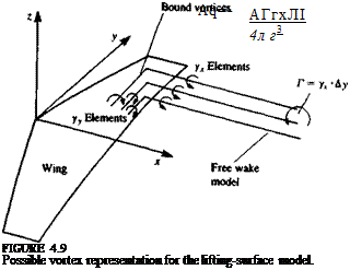
distribution. This model is physically very easy to construct and the velocity Aq due a vortex line element d with a strength of АГ will be computed by the Biot-Savart law (r is defined by Eq. (4.32)):

Now if vortices are distributed over the wing and wake (Fig. 4.9), then if those elements that point in the у direction are denoted as yy, and in the x direction as yx, then the component of velocity normal to the wing (down – wash), induced by these elements is

. . -i

iK*,y, z)= —

*t71 •’wing+wake

It appears that in this formulation there are two unknown quantities per point (yx, Уу) compared to one (ju) in the case of the doublet distribution. But, according to the Helmholtz vortex theorems (Section 2.9) vortex strength is constant along a vortex line, and if we consider the vortex distribution on the wing to consist of a large number of infinitesimal vortex lines then at any point on the wing дух/ду = Эуу/Эх and the final number of unknowns at a point is reduced to one.

As was shown earlier (in Section 3.14) for a vortex distribution,

beginning at the leading edge (L. E.)

Ф(х, уо, 0±) = f u(xt, yo,0±)dx!

•’L. E.

(4.48)

and

ДФ(дг, уо) = Yy(x і, Уо) dx і Jl. e.

(4.49)

The velocity potential on the wing at any point x (y = y0 = const.) can be obtained by integrating the x component of the velocity along an jt-wise line

Yy(x – x0) + yx(y – Уо)
[(x-Xof + iy-yof + z2]3*

ZERO THICKNESS CAMBERED WING AT ANGLE OF ATTACK—LIFTING SURFACES image129

To construct the lifting surface equation for the unknown y, the wing-induced downwash of Eq. (4.46) must be equal and opposite in sign to the normal component of the free-stream velocity:

Solution for the unknown doublet or vortex strength in Eq. (4.45) or Eq.

(4.50) allows the calculation of the velocity distribution. The method of obtaining the corresponding pressure distribution is described in the next section.

SYMMETRIC WING WITH NONZERO THICKNESS AT ZERO ANGLE OF ATTACK

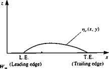
Consider a symmetric wing with a thickness distribution of rj,(x, у) at zero angle of attack, as shown in Fig. 4.4. The equation to be solved is

У2Ф = 0 (4.29)

Here the subscript is dropped for simplicity. The approximate boundary condition to be fulfilled at the z = 0 plane is

Tp (*, У, 0±) = ± Tp G« (4- 30)

az dx

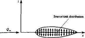
The solution of this problem can be obtained by distributing basic solution elements of Laplace’s equation. Because of the symmetry, as explained in Chapter 3, a source/sink distribution can be used to model the flow, and should be placed at the wing section centerline, as shown in Fig. 4.5. Recall that the potential due to such a point source element a, is

Подпись: (4.31)—a 4 nr

where r is the distance from the point singularity located at (jc0> Уо, Zo) (see Section 3.4)

r = V(x – JC0)2 + (y – Уо)2 + (z – Zo)2 (4.32)

Now if these elements are distributed over the wing’s projected area on the x-y plane (zo = 0), the velocity potential at an arbitrary point (x, y, z) will be

SYMMETRIC WING WITH NONZERO THICKNESS AT ZERO ANGLE OF ATTACK

(4.33)


Note that the integration is done over the wing only (no wake). The normal velocity component w^x, y, z) is obtained by differentiating Eq. (4.33) with respect to z:

Подпись:. _ ЭФ _ z f q(*0, y0) dx о dyо

w{x, y,z) 4л Jwing [(x – x0)2 + (y – y0)2 + z2]3/2

n<

Подпись: C-FIGURE 4.4

Definition of wing thickness function i at an arbitrary spanwise location y.

FIGURE 4.5

image122Method of modeling the thickness problem by a source/sink distribution.
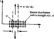
To find w(x, y, 0), a limit process is required (see Section 3.14) and the result is:

w(x, y, 0±)= lim w(x, y, z) = ± °^X’ ^ (4.35)

z—►0± /

where + is on the upper and — is on the lower surface of the wing, respectively.

This result can be obtained by observing the volume flow rate due to a Ax long and Ay wide source element with a strength a(x, y). A two – dimensional section view is shown in Fig. 4.6. Following the definition of a source element (Section 3.4) the volumetric flow 2 produced by this element is then

2 = o(x, y) Ax Ay

But as dz-*0 the flux from the sides becomes negligible (at z = 0±) and only the normal velocity component w(x, y, 0±) contributes to the source flux. The above volume flow feeds the two sides (upper and lower) of the surface element and, therefore 2 = 2w(x, y, 0+) Ax Ay. So by equating this flow rate with that produced by the source distribution,

2 = 2w(x, y, 0+) Ax Ay = o(x, y) Ax Ay

we obtain again

w(x, y, 0±) = ±^p2 (4.35)

Подпись: A*Подпись:image123FIGURE 4.4

Segment of a source distribution on the z = 0 plane.

Substituting Eq. (4.35) into the boundary condition results in

— (X у 0±) = ±^Q =±a{x’y) gz(x, y,v±> ± dxu„ ± 2

or

Подпись: (4.36)a(x, y) = 2Q^(x, y)

X’y’ 2 2я Jwing V(* – x0)z + (у – Уо)2 + Z2

dV,(x0, Уо),

u{x, y, z) = JZ [

ZJt Jwil

[(* – X0)2 + (y – Уо) + z2]312

image124 SYMMETRIC WING WITH NONZERO THICKNESS AT ZERO ANGLE OF ATTACK

So in this case the solution for the source distribution is easily obtained after substituting Eq. (4.36) into Eq. (4.33) for the velocity potential and differentiating to obtain the velocity held:

The pressure distribution due to this solution will be derived later, but it is easy to observe that since the pressure held is symmetric, there is no lift produced due to thickness.

SEPARATION OF THE THICKNESS AND THE LIFTING PROBLEMS

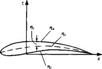
At this point of the discussion, the boundary condition (Eq. (4.17)) is defined for a thin wing and is linear. The shape of the wing is then defined by the contours of the upper r]u and lower r), surfaces as shown in Fig. 4.2,

z = t)u{x, y) (4.18a)

z = ri,(x, y) (4.18b)

This wing shape can also be expressed by using a thickness function r/„ and a camber function ijc, such that

r}c = 2(,nu + til) (4.19a)

Vt = 2(riu-Vi) (4.19b)

Therefore, the upper and the lower surfaces of the wing can be specified alternatively by using the local wing thickness and camberline (Fig. 4.2):

Ли = гіс + r, (4.20a)

Vi = Tlc- V, (4.20b)

Now, the linear boundary condition (Eq. (4.17)) should be specified for both the upper and lower wing surfaces,

(4.21&)

The boundary condition at infinity (Eq. (4.2)), for the perturbation potential Ф, now becomes

ІітУФ = 0 (4.21c)

Г-* oo

Since the continuity equation (Eq. (4.11)) as well as the boundary conditions (Eqs. (4.21a-c)) are linear, it is possible to solve three simpler

image119

image120,image121

FIGURE 4.3

Decomposition of the thick cambered wing at an angle of attack problem into three simpler problems.

problems and superimpose the three separate solutions according to Eqs. (4.21a), and (4.21b), as shown schematically in Fig. 4.3. Note that this decomposition of the solution is valid only if the small-disturbance approxima­tion is applied to the wake model as well. These three subproblems are:

1. Symmetric wing with nonzero thickness at zero angle of attack (effect of

thickness)

о

II

4

*>

(4.22)

with the boundary condition:

(4.23)

where + is for the upper and – is for the lower surfaces.

2. Zero thickness, uncambered wing at angle of attack (effect of angle-of – attack)

V2<&2 = 0 (4.24)

0±) = – Q~a (4-25)

3. Zero thickness, cambered wing at zero angle of attack (effect of camber)

V2<&3 = 0 (4.26)

^W,0 ±)=~C – (4-27)

The complete solution for the cambered wing with nonzero thickness at an angle of attack is then

Ф = Ф, + Ф2 + Ф3 (4.28)

Of course, for Eq. (4.28) to be valid all three linear boundary conditions have to be fulfilled at the wing’s projected area on the z = 0 plane.

THE BOUNDARY CONDITION ON THE WING

In order to satisfy boundary condition of Eq. (4.3), on the wing, the geometrical information about the shape of the solid boundaries is required. Let the wing solid surface be defined as

Z = Т}(х, У) (4.5)

and in the case of a wing with nonzero thickness two such functions will describe the upper (ru), and the lower (»/,) surfaces (Fig. 4.2). In order to find the normal to the wing surface, a function F{x, y, z) can be defined such that

F(x, y, z) = z- T}(x, y) = 0 (4.6)

and the outward normal on the wing upper surface is obtained by using Eq. (2.26):

Подпись:VF____ 1_ / Эту drj

[VFpiVFi Э*’_3y ‘ /

whereas on the lower surface the outward normal is — n.

The velocity potential due to the free-stream flow can be obtained by using the solution of Eq. (3.52):

Ф., = U^x + Жс2 (4.8)

and, since Eq. (4.1) is linear, its solution can be divided into two separate parts:

Ф* = Ф + Ф„ (4.9)

Substituting Eqs. (4.7) and the derivatives of Eqs. (4.8) and (4.9) into the

image117FIGURE 4.2

Definitions for wing thickness, upper and lower surfaces, and mean camberline at an arbitrary spanwise location y.

V3>* – n = УФ*

Подпись: VF VF THE BOUNDARY CONDITION ON THE WING Подпись: in. dx’

boundary condition (Eq. (4.3)) requiring no flow through the wing’s solid boundaries results in

(4.10)

The intermediate result of this brief investigation is that the unknown is the perturbation potential Ф, which represents the velocity induced by the motion of the wing in a stationary frame of reference. Consequently the equation for the perturbation potential is

У2Ф = 0 (4.11)

and the boundary conditions on the wing surface are obtained by rearranging дФ/дг in Eq. (4.10):

Подпись: ЭФ dz Подпись: on z = rjimage118(4.12)

Now, introducing the classical small-disturbance approximation will allow us to further simplify this boundary condition. Assume

ЭФ

dx

dy

dz

Подпись: (4.13)G« ’ G – ’ G

Подпись: in dx Подпись: «1, THE BOUNDARY CONDITION ON THE WING Подпись: «і Подпись: and Подпись: = tan a = a « 1 Подпись: (4.14)

Then, from the boundary condition of Eq. (4.12), the following restrictions on the geometry will follow:

This means that the wing must be thin compared to its chord. Also, near stagnation points and near the leading edge (where drj/dx is not small), the small perturbation assumption is not valid.

Accounting for the above assumptions and recalling that ~ Q^a and the boundary condition of Eq. (4.12) can be reduced to a much simpler form,

£<«.*,>-ft(fH (415)

It is consistent with the above approximation to also transfer the boundary conditions from the wing surface to the x-y plane. This is accomplished by a Taylor series expansion of the dependent variables, e. g.,

dФ dФ ді^Ф

~^(x, y,z = i]) = — (x, y,0) + T]-^(x, y,0) + O(t] ) (4.16)

Along with the above small-disturbance approximation, only the first term
from the expansion of Eq. (4.16) is used and then the first-order approxima­tion of boundary condition, Eq. (4.12) (no products of small quantities are kept), becomes

f <*->■■ °)"Є"(!Н <4-i7>

A more precise treatment of the boundary conditions (for the two – dimensional airfoil problem) including proceeding to a higher-order ap­proximation will be-considered in Chapter 7.

FORMULATION OF THE PROBLEM

One of the first important applications of potential flow theory was the study of lifting surfaces (wings). Since the boundary conditions on a complex surface can considerably complicate the attempt to solve the problem by analytical means, some simplifying assumptions need to be introduced. In this chapter these assumptions will be applied to the formulation of the steady three – dimensional thin wing problem and the scene for the singularity solution technique will be set.

4.1 DEFINITION OF THE PROBLEM

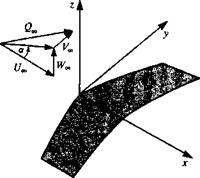
Consider the finite wing shown in Fig. 4.1, which is moving at a constant speed in an otherwise undisturbed fluid. A cartesian coordinate system is attached to the wing and the components of the free-stream velocity Q„ in the x, y, z frame of reference are (/„, V„, and W„, respectively. (Note that the flow is steady in this coordinate system.) The angle of attack a is defined as the angle between the free-stream velocity and the x axis and for the sake of simplicity side slip is not included at this point (VM = 0).

FIGURE 4.1

image116Nomenclature used for the definition of the finite wing problem.
If it is assumed that the fluid surrounding the wing and the wake is inviscid, incompressible and irrotational, the resulting velocity field due to the motion of the wing can be obtained by solving the continuity equation

V2O* = 0 (4.1)

where Ф* is the velocity potential, as defined in the wing frame of reference. (Note that Ф* is the same as Ф in Chapter 3 and the reason for introducing this notation will become clear in the next section.) The boundary conditions require that the disturbance induced by the wing will decay far from the wing:

lim УФ* = Q« (4.2)

Г—

which is automatically fulfilled by the singular solutions (derived in Chapter 3) such as the source, doublet, or the vortex elements. Also, the normal component of velocity on the solid boundaries of the wing must be zero. Thus, in a frame of reference attached to the wing,

УФ* • n = 0 (4.3)

where n is an outward normal to the surface (Fig. 4.1). So, basically, the problem reduces to finding a singularity distribution that will satisfy Eq. (4.3). Once this distribution is found, the velocity q at each point in the field is known and the corresponding pressure p will be calculated from the steady – state Bernoulli equation:

P~ + ^QZ = P+^<12 (4-4)

The analytical solution of this problem, for an arbitrary wing shape, is complicated by the difficulty of specifying boundary condition of Eq. (4.3) on a curved surface, and by the shape of a wake. The need for a wake model follows immediately from the Helmholtz theorems (Section 2.9), which state that vorticity cannot end or start in the fluid. Consequently, if the wing is modeled by singularity elements that will introduce vorticity (as will be shown
later in this chapter), these need to be “shed” into the flow in the form of a wake.

To overcome the difficulty of defining the zero normal flow boundary condition on an arbitrary wing shape some simplifying assumptions are made in the next section.

SURFACE DISTRIBUTION OF THE BASIC SOLUTIONS

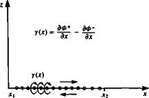
The results of Sections 3.2 and 3.3 indicate that a solution to the flow over arbitrary bodies can be obtained by distributing elementary singularity solutions over the modeled surfaces. Prior to applying this method to practical problems, the nature of each of the elementary solutions needs to be investigated. For simplicity, the two-dimensional point elements will be distributed continuously along the x axis in the region x1—*x2-

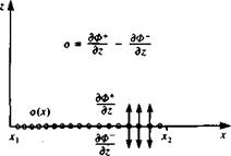
SOURCE DISTRIBUTION. Consider the source distribution of strength per length o(x) along the x axis as shown in Fig. 3.19. The influence of this distribution at a point P(x, z) is an integral of the influences of all the point elements: . fX2

Ф(х, 2) = 2л J 0(<X^ ІП “ *o)2 + z2 dxо (3.130)

(ЗШ)

z^“ <3132)

In order to investigate the properties of such a distribution for future modeling purposes, the type of discontinuity across the surface needs to be

image112FIGURE 3.19

Source distribution along the x axis.

Подпись:image113Гк, зф +

[Note—-

w(x, 0+) = lim

z—*-0+

, (x – *o)2 + Z

SURFACE DISTRIBUTION OF THE BASIC SOLUTIONS Подпись: dx0 Подпись: (3.133)

examined. Since each source emits fluid in all directions, intuitively we can see that the resulting velocity will be away from the surface, as shown in Fig. 3.19. From the figure it is clear that there is a discontinuity in the w component at 2 = 0. Note that as z-»0 the integrand in Eq. (3.132) is zero except when x0 = x. Therefore, the value of the integral depends only on the contribution from this point. Consequently, o(x0) can be moved out of the integral and replaced by a(x). This suggests that the limits of integration do not affect the value of the integral and for convenience can be replaced by T®. Also, from the z dependence of the integrand in Eq. (3.132), the velocity component when approaching z = 0 from above the x axis, w+, is in the opposite direction to w~, which is the component when approaching the axis from below. For the velocity component w+, Eq. (3.132) becomes

To evaluate this integral it is convenient to introduce a new integration variable A,

л._*!

z z

SURFACE DISTRIBUTION OF THE BASIC SOLUTIONS

and the integration limits for z—*0+ become ±®. The transformed integral becomes

FIGURE 3.20

image114Doublet distribution along the x axis.

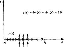
distribution, pointing in the z direction [p = (0, ft)], at a point P(x, z) is an

integral of the influences of the point elements between де,-»

*2 (Fig. 3.20).

ч 1 f*2 z

Ф(Х’І)= 2*1 ^

(3.137)

, x 1 Г2 / ч (x-x0)z

U(X’Z)-*l "Ы((x-r^ + zT*”

(3.138)

/ ч 1 Г2 / ч (X-Xof-Z2 ,

W<-X’X)‘ 2ЯІ,

(3.139)

Ф(*, 0±) = T

Подпись: 2 Подпись: (3.140)

Note that the velocity potential in Eq. (3.137) is identical in form to the w component of the source (Eq. (3.132)). Approaching the surface, at z = 0±, this element creates a jump in the velocity potential. This analogy yields

SURFACE DISTRIBUTION OF THE BASIC SOLUTIONS
Подпись: (3.141)

This leads to a discontinuous tangential velocity component given by

Since the doublet distribution begins at the circulation Г(дс) around a path surrounding the segment is

Подпись:Подпись: (3.143)Г(дс) = f и(дс„, 0+) dx0 + f ы(х0, 0-) dx0 = – fi(x)

Лі Jx

which is equivalent to the jump in the potential

Г(дг) = Ф(дс, 0+) – Ф(*, 0—) = – fi(х) = ДФ(дс)

VORTEX DISTRIBUTION. In a similar manner the influence of a vortex

FIGURE 3.21

image115Vortex distribution along the x axis.

distribution at a point P(x, z) is an integral of the influences of the point elements between xx—*x2 (Fig. 3.21).

Ф(дс, z) = -— f y(x0) tan-1 – — dx0 (3.144)

•’xj Др — X0

(3145)

"<*• гЫ Tx s <3146>

Here the и component of the velocity is similar in form to Eqs. (3.132) and (3.137) and there is a jump in this component as z = 0±. The tangential velocity component is then

u(x, 0±) = — (x,0±) = ±?y (3.147)

The contribution of this velocity jump to the potential jump, assuming that Ф = 0 ahead of the vortex distribution is

ДФ(дг) = Ф(дс, 0+)-Ф(дг, 0-) = J ^~dx0-j – y-~dx0

The circulation Г is the closed integral of u(x, 0) dx which is equivalent to that of Eq. (3.142). Therefore,

Г(х) = Ф(х, 0+) – Ф(х, 0-) = ДФ(х) (3.148)

Note that similar flow conditions can be modeled by either a vortex or a doublet distribution and the relation between these two distributions is

Подпись: Г=-д(3.149)

Подпись: y(x) = - Подпись: dx Подпись: (3.150)

Comparing Eq. (3.141) with Eq. (3.147) indicates that a vortex distribu­tion can be replaced by an equivalent doublet distribution such that

SOME REMARKS ABOUT THE FLOW OVER THE CYLINDER AND THE SPHERE

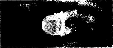
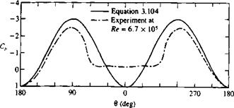
The examples of the flow over a cylinder and a sphere clearly demonstrate the principle of superposition as a tool for deriving particular solutions to Laplace’s equation. From the physical point of view, these results fall in a range where potential flow-based calculations are inaccurate owing to flow separation. The pressure distribution around the cylinder, as obtained from Eq. (3.104), is shown in Fig. 3.14 along with some typical experimental results. Clearly, at the frontal stagnation point (0 = л) the results of Eq. (3.104) are close to the experimental data, whereas at the back the difference is large. This is a result of the streamlines not following the surface curvature and separating from this line as shown in Fig. 3.13; this is called flow separation.

The theoretical pressure distribution (Eq. (3.125)) for the sphere, along with the results for the cylinder, are shown in Fig. 3.17. Note that for the three-dimensional case the suction pressures are much smaller (relieving

SOME REMARKS ABOUT THE FLOW OVER THE CYLINDER AND THE SPHERE

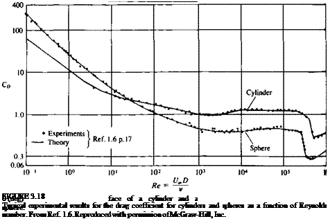
effect). Experimental data for the sphere shows that the flow separates too but the low pressure in the rear section is smaller. Consequently, the actual drag coefficient of a sphere is less than that of an equivalent cylinder, as shown in Fig. 3.18 (for Re > 2000). This drag data is a result of the skin friction and flow separation pattern, which is strongly affected by the Reynolds number. Clearly, for the laminar flows (Re < 2000) the drag is large owing to larger flow

separation behind the body, which is being reduced as the turbulent flow momentum transfer increases (Re > 10s, see Schlichting,16 p. 17). Note that the inviscid flow results do not account for flow separation and viscous friction near the body’s surface and therefore the drag coefficient for both cylinder and sphere is zero. This fact disturbed the French mathematician d’Alembert, in the middle of the seventeenth century, who arrived at this conclusion that the drag of a closed body in two-dimensional inviscid incompressible flow is zero (even though he realized that experiments result in a finite drag). Ever since those early days of fluid dynamics this problem has been known as the d’Alembert’s paradox.

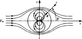
SUPERPOSITION OF A THREE – DIMENSIONAL DOUBLET AND FREE STREAM: FLOW AROUND A SPHERE

The method of the previous section can be extended to study the case of the three-dimensional flow over a sphere. The velocity potential is obtained by the superposition of the free stream potential of Eq. (3.51) with a doublet pointing in the negative x direction (Eq. (3.34)). The combined velocity potential is

image107

image108

(3.114)

image109(3.116)

1 Подпись: (3.117)ЭФ r sin в дер

At the sphere surface, where r = R, the zero normal flow boundary condition is enforced (qr = 0),

4r = (cL – ^3) cos 0 = 0 (3.118)

This condition is met at 0 = я/2, Зя/2 and in general, when the quantity in the parentheses is zero. This second condition is used to determine the doublet strength,

H = Ua*R3 (3.119)

which means that qT = 0 at r = R, which is the radius of the sphere. Substituting the strength p into the equations for the potential and the velocity components results in the flowfield around a sphere with a radius R:

Ф = f/oo cos d(r +

(3.120)

/ R3

q, = cos 0^1 —

(3.121)

/ R* qe = sin 0^1 + ^5)

(3.122)

To obtain the pressure distribution over the sphere, the velocity components at r = R are found:

qr = 0 qe = -|f/» sin 0 (3.123)

The stagnation points occur at 0 = 0 and 0 = я, and the maximum velocity at 0 = я/2 or 0 = Зя/2. The value of the maximum velocity is which is smaller than in the two-dimensional case.

The pressure distribution is obtained now with Bernoulli’s equation

p – p=o = – 4 sin2 0)

(3.124)

and the pressure coefficient is

c’-w=(1-?sin! e)

2PVoc,

(3.125)

It can be easily observed that at the stagnation points 0 = 0 and я (where q = 0) Cp = 1. Also the maximum velocity occurs at the top and bottom of the sphere (в = я/2, Зя/2) and the pressure coefficient there is —5/4.

Because of symmetry, lift and drag will be zero, as in the case of the flow over the cylinder. However, the lift on a hemisphere is not zero (even without introducing circulation); this case is of particular interest in the held of road-vehicle aerodynamics. The flow past a sphere can be interpreted to also represent the flow past a hemisphere on the ground since the x axis is a streamline and can be replaced by a solid surface.

The lift force acting on the hemisphere’s upper surface is

Подпись: (3.126)p„o) sin 0 sin <p dS

and the surface element dS on the sphere is

dS = (R sin 0 dq>){R dd)

Substituting dS and the pressure from Eq. (3.124), the lift of the hemisphere is

L = – f f 2P^(1 _ 4 sin2 sin2 0 sin qj dd dcp Jo Jo

= – Ipulf (1 – 3 Sin2 0)2R2 sin2 0 de = – PR2Ui – ^) = %npR2Ul

(3.127)

The lift and drag coefficients due to the upper surface are then

Подпись:L 11

8

Подпись: ■ = 0Подпись: Cn =D

PUI lR2

For the complete configuration the forces due to the pressure distribution on the flat, lower surface of the hemisphere must be included, too, in this calculation.

SUPERPOSITION OF DOUBLET AND FREE SYSTEM: FLOW AROUND A CYLINDER

image96,image97,image98

Consider the superposition of the free stream potential of Eq. (3.51), where x = r cos 0 in cylindrical coordinates, with the potential of a doublet (Eq. (3.68)) pointing in the negative x direction [ц = (~ц, 0)]. The combined flow, as shown in Fig. 3.11, has the velocity potential

1 ЗФ / U

<395)

If this flow combination is thought of as a limiting case of the flow in Section 3.10 with the source and sink approaching each other, it is expected that the oval will approach a circle in this limit. To verify this, note that qr = 0 for r = У/р/2лик for all 0 (from Eq. (3.94)) and the radial direction is normal to the circle. If we take r = R as the radius of the circle, then the strength of the doublet is

ft = UJ2nR2 (3.96)

Substituting this value of fi into Eqs. (3.93), (3.94), and (3.95) results in the flowfield around a cylinder with a radius R:

/ R2 Ф = U„ cos 0^r H—————- J

(3.97)

/ R2 qr = U„ cos 0^1 — – jjj

(3.98)

/ r2 qe = – U„sin e[l + ^jj

(3.99)

For the two-dimensional case, evaluation of the stream function can readily provide the streamlines in the flow (by setting 4* = const.). These results for the cylinder in a free stream can be obtained, too, by the superposition of the free stream and the doublet [with (-/i, 0) strength] stream functions:

4» = f/„rsin(9-^-— (3.100)

2я t

The stagnation points on the circle are found by letting qe = 0 in Eq. (3.99), and are at 0 = 0 and 0 = л. The value of V at the stagnation points 0 = 0 and 6 = л (and therefore along the stagnation streamline) is found from Eq. (3.100) to be V = 0. This is equivalent to requiring that qr(R, 0) = 0, and the strength of Ц again is given by Eq. (3.96). Substituting ц in terms of the cylinder radius into Eq. (3.100) yields

4> = U„sine(r-!yJ (3.101)

This describes the streamlines of the flow around the cylinder with radius R (Fig. 3.12). These lines are perpendicular to the potential lines of Eq. (3.97).

To obtain the pressure distribution over the cylinder, the velocity components are evaluated at r = R:

Подпись: (3.102)qr = 0 qe = —21/„ sin 0

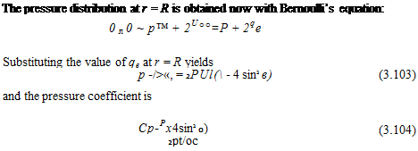
Подпись: The pressure distribution at r = R is obtained now with Bernoulli’s equation: 0 л 0 ~ p™ + 2U°°=P + 2qe Substituting the value of qe at r = R yields p -/>«, = 2PUl( - 4 sin2 в) (3.103) and the pressure coefficient is Cp-Px4sin2 0) 2pt/oc (3.104)

It can be easily observed that at the stagnation points 0 = 0 and л (where q = 0) Cp = 1. Also the maximum speed occurs at the top and bottom of the cylinder (0 = л/2, Зл/2) and the pressure coefficient there is —3.

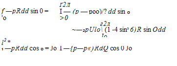
To evaluate the components of the fluid dynamic force acting on the cylinder, the above pressure distribution must be integrated. Let L be the lift per unit width acting in the z direction and D the drag per unit width acting in the x direction. Integrating the components of the pressure force on an element of length R dd leads to

Подпись: f —pRdd sin 0 = Ґ2Л I — (p — poo)/? dd sin 0 'o >0 г2л ~—2pUlo (1 -4 sin2 6)R sin Odd Jo l2* 1 —pRdd cos 0 = Jo I —{p—p«)RdQ cos 0 Jo Подпись:image99

Подпись: FIGURE 3.12 Streamlines due to the addition of a doublet and a uniform flow (flow around a cylinder).
image100

(3.105)

(3.106)

Here the pressure was replaced by the pressure difference p – term of Eq. (3.103), and this has no effect on the results since the integral of a constant pressure around a closed body is zero. A very interesting result of this potential flow is that the fore and aft symmetry leads to pressure loads that

image101

FIGURE 3.13

Hydrogen bubble visualization of the separated water flow around a cylinder at a Reynolds number of 0.2 x 10⁶ (Courtesy of K. W. McAlister and L. W. Carr, U. S. Army Aeroflightdynam – ics Directorate, AVSCOM).

cancel out. In reality the flow separates, and will not follow the cylinder’s rear surface, as shown in Fig. 3.13. The pressure distribution due to this real flow, along with the results of Eq. (3.104), are plotted in Fig. 3.14. This shows that at the front section of the cylinder, where the flow is attached, the pressures are well predicted by this model. However, behind the cylinder, because of the flow separation, the pressure distribution is different.

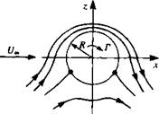
In this example, because of the symmetry in the upper and the lower flows (about the x axis), no lift was generated. A lifting condition can be obtained by introducing an asymmetry, in the form of a clockwise vortex with strength Г situated at the origin. The velocity potential for this case is

Ф = f/,0 cos в^г + — ~~ 0 (3.107)

image102

FIGURE 3.14

Theoretical pressure distribution (solid curve) around a cylinder compared with experimental data at Reynolds number of 6.7 x 10s (chain curve) from Ref 1.6.

image103 Подпись: (3.108)

The velocity components are obtained by differentiating the velocity potential

which is the same as for the cylinder without the circulation, and

Подпись: qe = -1/„ sin вПодпись: Г 2лг image104(3.109)

Подпись: 2 MR Подпись: qe = —2l/„ sin в — Подпись: and by solving for qe = 0,
Подпись: sin 0. = — Подпись: (3.110) (3.111)

This potential still describes the flow around a cylinder since at r = R the radial velocity component becomes zero. The stagnation points can be obtained by finding the tangential velocity component at r = R,

These stagnation points (located at an angular position 8S) are shown by the two dots in Fig. 3.15 and lie on the cylinder as long as Г < 4nRU„.

The lift and drag will be found by using Bernoulli’s equation, but because of the fore and aft symmetry no drag is expected from this calculation. For the lift, the tangential velocity component is substituted into the Bernoulli equation and

L = J -(p – p^)R d6 sin в = – J^ [^^_2 (2^«=sin в + j sin 8Rdd

= f sin2 8dd = pUJ (3.112)

Л Jo

This very important result states that the force in this two-dimensional flow is directly proportional to the circulation and acts normal to the free stream. A generalization of this result was discovered independently by the German mathematician M. W. Kutta in 1902 and by the Russian physicist N. E. Joukowski in 1906. They observed that the lift per unit span on a lifting airfoil or cylinder is proportional to the circulation, consequently the Kutta-

image105FIGURE 3.15

Streamlines for the flow around a cylinder with circula­tion Г.

Notation used for the generalized Kutta – Joukowski theorem.

Подпись: FIGURE 3.16image106Joukowski theorem (which will be derived in Chapter 6) states:

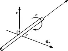
The resultant aerodynamic force in an incompressible, inviscid, irrotational flow in an unbounded fluid is of magnitude pQ_Г per unit width, and acts in a direction normal to the free stream. (Note that the speed of the free stream is taken to be since the stream may not be parallel to the x axis.)

Using vector notation, this can be expressed as

Подпись: (3.113)F = pQoo X Г

where F is the aerodynamic force per unit width and acts in the direction determined by the vector product, as shown schematically in Fig. 3.16. Note that positive Г is defined according to the right-hand rule.