Category Aircraft Flight

Flow in a supersonic wind-tunnel

The fact that radically different flows occur at sub – and supersonic speeds with objects having identical geometric features is also graphically illustrated by the flow in a duct of the type which is used in supersonic wind-tunnels (Fig. 5.4).

If the tunnel is run subsonically then, as would be expected from Chapter 1 the speed of flow increases until the narrowest portion (the throat) is reached and decreases again as the duct area increases. If, however, the tunnel is running supersonically, the speed continues to increase downstream of the throat, even though the cross-sectional area is getting larger.

At first sight it may seem that this is impossible because the same mass flow must pass each section in unit time. Thus it would appear that a lower speed of flow will be needed at a point in the duct where the cross-sectional area is high, and vice versa.

The solution to this dilemma lies in the fact that the density of the air reduces as the speed is increased. At low speed this effect is not very significant, but as the speed increases the effect becomes so pronounced that an increase in duct area is required to pass the mass flow in spite of the fact that the speed is also increasing (Fig. 5.4).

This change of density starts to become noticeable some time before the flow actually becomes supersonic in that pressures predicted by the Bernoulli equation (Chapter 1) become progressively less accurate. Thus one way of distinguishing between high and low speed flows is to ask the question whether the density changes within the flow are significant or not. For this reason flow at high speed is sometimes referred to as compressible flow. This distinction is valid for ‘external’ flows, such as the flow round the aerofoil discussed above, as well as ‘internal’ flows such as the supersonic wind-tunnel duct.

The gas turbine

The gas turbine was originally developed primarily as a practical device for providing jet propulsion, since it was realised that this would overcome the speed limitations imposed by propeller propulsion. The other factor that prompted its original development, was the realisation that it would operate satisfactorily at high altitudes. As with the high speed ducted fan described earlier, the air slows down as it enters a gas turbine in high speed flight, which means that the air pressure and density increase at inlet. This increase can com­pensate for the low atmospheric air density at high altitude. Both high speed and high altitude flight have obvious advantages for military aircraft.

A major feature of the gas turbine is the considerable amount of power that it can produce at high forward speeds. The effective power produced is the product of the thrust and the forward speed. For example, a large turbo-jet engine giving 250 kN (approx. 50,000 lb) of thrust would be producing around 60 megawatts (approx 80,000 bhp) at 240 m/s (approx 500 mph). The most powerful piston engines produced no more than about 2.5 megawatts (approx 3400 bhp). On the first experimental turbo-jet flight by the Heinkel He-178 (Fig. 6.17) in 1939, the engine was producing about as much equiva­lent power at maximum speed as the most powerful production piston engines of that time.

Other advantages of the gas-turbine engine compared to reciprocating engines are the high power-to-weight ratio, the virtual absence of reciprocating parts, and simpler less frequent maintenance.

The gas turbine

Fig. 6.17 The first turbo-jet aircraft

The Heinkel He-178 made its maiden flight in August 1939 (Photo courtesy of the Royal Aeronautical Society)

Endurance with turbo-jet propulsion

For a turbo-jet, the fuel flow rate is approximately proportional to the thrust produced by the engine, regardless of speed or altitude. The best endurance will thus occur at the minimum thrust setting because this will give the lowest fuel flow. The lowest possible thrust, and hence best endurance, will be obtained when the aircraft is flying at its minimum drag speed rather than the minimum power condition.

The maximum time for which the aircraft can be kept airborne will be approximately independent of both wing loading and altitude, because the magnitude of the minimum drag is not influenced by these parameters. How­ever the speed at which minimum drag is obtained, and hence the speed for best endurance, increases with both wing loading and altitude.

Some further non-aerodynamic considerations in wing design

We have mentioned structural problems and how they influence the final design of a wing. There are also a number of other considerations which we will discuss briefly here in order to remind ourselves that the aerodynamicist cannot have things all his own way in the design process.

As well as providing lift the wing usually has other important functions. One of these functions in most aircraft is to act as the main fuel tank. Using the wings for this has a number of advantages. Firstly it uses up an otherwise

Fig. 9.18 Area rule

The Rockwell B1 bomber has a narrow fuselage ‘waist’ at the junction with the wing in order to preserve the correct lengthwise distribution of overall cross­sectional area

unattractively shaped storage volume for a useful purpose. Secondly the fuel weight can be spread over the span of the wing, rather than concentrating it all in the fuselage. Thus we can get away with a lighter wing structure because of the reduced bending moments along the wing.

In many aircraft, particularly transport aircraft, it is very convenient to store all the fuel in the wings and this immediately leads to the requirement that the wing must have a certain minimum volume quite apart from the structural problems we have already mentioned. This may well mean that some comprom­ise had to be made in the aerodynamic performance of the wing. This sort of problem gives some idea of the complexity of the design process. Because the aerodynamic performance is reduced, more fuel will be required, and so the designer must go round the loop of choosing wing capacity and performance until a satisfactory solution is obtained.

Before we leave the subject let us look at a couple of less obvious design choices which must be made. The first of these concerns the question of where we put the main undercarriage legs. With a nose wheel undercarriage these must clearly be behind the aircraft centre of gravity, or the aircraft will topple onto its tail while at rest on the ground. To get a reasonable wheel separation and to keep the fuselage clear it is generally preferable to mount the undercarriage in the wings. However, with a swept wing, the centre of gravity may lie near the trailing edge where the wing is too thin to house the retracted gear, and too weak locally to support the weight of the aircraft. One solution which is commonly employed is to use a cranked trailing edge (Fig. 9.19). This, fortunately, fits in quite well with some of the other requirements which have

Fig. 9.19 Cranked trailing edge

This may be necessary to get the undercarriage in the right place. It also provides a convenient place for engine pylons

already been seen to apply at the centre section. Furthermore, extending the wing chord in this region enables a thick physical section to be used, which is needed for the structure and to house the undercarriage; alternatively the thickness-to-chord ratio can be reduced to give an aerodynamically thinner wing. This again can be helpful in keeping the local Mach number down at the centre section where the local flow speed has been raised by the presence of the fuselage. Another important advantage is that the use of a straight trailing edge close to the fuselage makes it much easier to fit trailing-edge flaps close to the wing fuselage junction.

Another unexpected factor may enter into the design of the cranked inboard portion of the wing. There will clearly have to be a break in the trailing-edge flap to accommodate an underwing pylon-mounted engine. It is therefore con­venient to mount the engine at the junction between the swept and unswept trailing-edge regions (Fig. 9.19). The distance of the engines from the centreline has important implications from the point of view of aircraft controllability in the event of engine failure, particularly at take-off when full thrust is being employed. The further outboard the engine is mounted the larger the fin and rudder assembly needed to provide adequate control in these circumstances. This is one more factor which must be carefully considered, and so we see that we cannot just consider the wing itself in trying to achieve our optimum design for changes in the wing design can have important repercussions elsewhere on the aircraft.

Another factor which may limit the way in which we can achieve our desired wing geometry is the manufacturing process itself. If a conventional wing con­struction of light alloy is to be used, the complexity of the three-dimensional surface which can be achieved is limited, and it may not be possible to build in economically all the variations of twist and camber that we would like if given an entirely free hand. This is another potential advantage presented by more modern composite materials – they offer the possibility, not only of building in tailored stiffness characteristics, but the facility to make more complicated shapes than is possible with more conventional constructional materials (see Fig. 14.6).

Conditions for longitudinal static stability

It will be seen that the centre of gravity is further forward in the stable case of Fig. 11.5 than in the unstable one of Fig. 11.6. Also, in the stable case, the wing is set at a higher incidence than the tail. The difference between the incidence angles at which the wing and tail are set is called the longitudinal dihedral. By comparing Figs 11.5 and 11.6 it can be seen that the longitudinal dihedral influences the production of a favourable restoring moment. In the stable case of Fig. 11.5 the longitudinal dihedral angle is positive. In the unstable case of Fig. 11.6 the angle is negative. The A-10 Thunderbolt shown in Fig. 11.7 shows a noticeable degree of positive longitudinal dihedral.

In fact, it is not actually the longitudinal dihedral (the difference between wing and tail incidences) that matters, but the difference between wing and tail lift coefficients in the initial trimmed condition. From mathematical analysis we find that for stability, the tail lift coefficient in the trimmed condition should be less than that of the wing by a sufficient margin to overcome the destabilising effects of the camber etc. The longitudinal dihedral effect, though important, is only one of the many influences on stability that appear in a full analysis.

If the centre of gravity of the aircraft is moved forward, the tail down – force has to be increased, to keep the aircraft trimmed. This requires that the

Fig. 11.7 The Fairchild-Republic A-10 Thunderbolt, showing high thrust line and a noticeable longitudinal dihedral

tail incidence should be made more negative, or that the elevator should be raised. Either of these effects will increase the effective longitudinal dihedral, and increase the static stability. Thus, the further forward the centre of gravity position is moved, the greater will be the longitudinal static stability.

It should be noted that the centre of gravity does not have to be in front of the aerodynamic centre of the wing for stability, although this is a common condition for conventional aircraft.

The rearward CG position at which the aircraft is just on the verge of being unstable or is neutrally stable is called the neutral point.

For a conventional aircraft trimmed for steady level flight, the tailplane normally has to produce very little lift, or even a downforce. For this reason, a symmetrical aerofoil is often used for the tailplane.

In situations where the tailplane has to produce a downforce, the wing and tail are effectively fighting each other, so the overall lift is less than that produced by the wing. The tailplane, however, still produces positive drag, and thus serves no useful purpose other than as a means of controlling and stabil­ising the aircraft. The extra drag produced in this way is called trim drag.

Effects of wind on landing

The above picture looks deceptively simple in that we have ignored any need for lateral control. Ideally the aircraft should be landing directly into the wind, but unfortunately, although airports are built so that the runway is aligned with the prevailing wind wherever possible, the weather is seldom completely obliging! Because of this it is necessary for the side wind to be allowed for dur­ing the approach so that the flightpath remains aligned with the runway.

This can be achieved in one of two ways. In the first of these ways the aircraft is flown with one wing low and the rudder is used to prevent a turn developing. In this way a steady sideslip can be used to counteract the side wind while keeping the aircraft aligned with the runway. In the second method the aircraft heading is altered to compensate for the wind and the resulting mis­alignment with the runway is corrected, largely by rudder control, just before touch-down in a process known as ‘kicking off drift’. These two methods are illustrated in Figs 13.9 and 13.10.

Sidewards drift is not the only problem posed by the wind on landing. Because the earth has its own, rather thick, boundary layer, the wind speed

Fig. 13.9 Effect of wind

Aircraft must be headed into wind to compensate for the component causing drift. Rudder is used to align aircraft axis with runway just before touch-down (‘kicking off drift’)

will reduce rapidly as the aircraft height reduces. This is known as ‘wind shear’ (Fig. 13.11). Not only this, there may be substantial gusts as well. This will obviously complicate the process of flying an accurate rate of descent on the glide. Also, if the air speed has been allowed to come too close to the stall there is a real danger of a stall being initiated.

Trailing vortex formation

The physical mechanism by which the trailing vortices are formed may be understood by reference to Fig. 2.6. On the underside of a wing, the pressure

Trailing vortex formation

Fig. 2.5 Trailing vortex formation

Flow visualisation using helium-filled microscopic soap bubbles. The flow spirals around a stable core originating from just inboard of the wing tip (Photo courtesy of ENSAM, Paris)

Trailing vortex formation

Fig. 2.6 Spanwise flow on a wing

(a) The air flows inwards on the upper surface and outwards on the lower. This is the source of the trailing vortices

(b) View from just downstream of the trailing edge

is higher than the surrounding atmosphere, so the air flows outwards towards the tips. On the upper surface, the pressure is low, and the air flows inwards. This results in a twisting motion in the air as it leaves the trailing edge. Thus, if we look at the air flow leaving the trailing edge from a viewpoint just downstream, as in Fig. 2.6(b), it will appear to rotate. Near each wing tip, the air forms into a well defined concentrated vortex, but a rotational tendency or vorticity occurs all along the trailing edge. Further downstream, all of the vorticity collects into the pair of concentrated trailing vortices (as shown in Fig. 2.10).

If the wing is completely constrained between the walls of a wind-tunnel, the outflow will not occur, and trailing vortices will not form. This ties up with the theory of vortex behaviour mentioned above: the vortices must either form a closed loop, or terminate in a wall. It also points to one of the problems of wind-tunnel testing; the fact that the presence of the tunnel walls influences the flow behaviour.

Effect on wind-tunnel testing

A major problem in wind-tunnel model testing arises if we rely solely on increasing the speed to correct the Reynolds number. Since the chord c of the model is smaller, we must make (pV )/u larger. This in turn means that, unless we do something about the density and viscosity, a 1/10 scale model would need to be run at 10 times the full-scale speed.

Unfortunately aircraft are large objects, and we often wish to make models of 1/10 scale or less. To simulate 100 m/s at 1/10 scale, we would need to

run the tunnel at 1000 m/s which is nearly three times the speed of sound at sea level! Clearly, the resulting supersonic conditions would ensure that the flow around the model was nothing like that for the full-size aircraft.

One way to avoid this difficulty, is to use a pressurised wind-tunnel. By increasing the pressure in the tunnel, the density and hence the Reynolds num­ber may be increased at any given air speed. A similar effect can be obtained by using a so-called cryogenic tunnel where the air is cooled (usually with liquid nitrogen) to decrease the viscosity coefficient p. Gases, unlike liquids, become less viscous as they are cooled. The density is also increased.

In order to obtain similar flow characteristics between model and full scale (a condition known as dynamic similarity), it turns out that there are other quantities that need to be matched in addition to the Reynolds number. For aeronautical work, the other really important one is the Mach number, the ratio of the relative flow speed (or aircraft speed) to the speed of sound. As we shall see, the speed of sound depends on the temperature, and thus quite a bit of juggling with speed, pressure and temperature is required, in order to get both the Reynolds and the Mach numbers in a test simultaneously matched to the full-scale values.

Although less important, we should really try to match the levels of tur­bulence in the oncoming air stream, which can be difficult, because in full scale, the aircraft can sometimes be flying through still, and hence non-turbulent air.

For fundamental investigations, and exploratory test programmes, it is still customary to use simple unpressurised tunnels. When the low speed character­istics of the aircraft are being investigated, the Mach number mismatch is un­important. The Reynolds number error can sometimes be reduced by sticking strips of sandpaper on the surface to provoke transition at the correct position, which can either be estimated, or determined from flight tests.

For tests at supersonic speeds the Mach number must be matched, which is quite easy, and the Reynolds number effect is often less important. Unfortunately, most airliners, and quite a few military aircraft spend most of their time flying faster than 70 per cent of the speed of sound, where both the Mach and Reynolds numbers are important. Wind-tunnels in which the pressure, temperature and Mach number can be controlled accurately to suit the size of model are expensive to build and run, especially for speeds close to the speed of sound, but they are essential for accurate development work.

Thrust and propulsion

Propulsion systems

It is tempting to try to divide the conventional aircraft propulsion systems into two neat categories; propeller and jet. Real propulsion devices, however, do not always fall into such simple compartments. In particular, gas-turbine propulsion covers a wide range from turbo-props to turbo-jets. To simplify matters, we shall look first at the two ends of this spectrum; by considering propeller propulsion at one end, and simple turbo-jet propulsion at the other. Later on, we shall look at the intermediate types such as turbo-fans and prop – fans, and also some unconventional systems.

Propeller propulsion

At one time, it looked as though the propeller was in danger of becoming obso­lete. Since the early 1960s, however, the trend has been reversed, and nowa­days nearly all subsonic aircraft use either a propeller or a ducted fan. Even the fan has lost some ground to advanced propellers, and we shall therefore pay more attention to propeller design than might have seemed appropriate a few years ago. It is worth noting, that in 1986, half a century after the first successful running of a jet engine, 70 per cent of the aircraft types on display at the Farnborough Air Display were propeller driven.

The blades of a propeller like those of the helicopter rotor can be thought of as being rotating wings. Since the axis of rotation of the propeller is hori­zontal, the aerodynamic force produced is directed forwards to provide thrust rather than upwards to generate lift. The thrust force is therefore related to the differences in pressure between the forward – and the rearward-facing surfaces of the blades.

Thrust and propulsionRelative flow

Surrounding

Подпись: stream-tube Thrust and propulsion Подпись: Surrounding

Fig. 6.1 The flow past a propeller in flight

In the process of producing this pressure difference, the propeller creates a slipstream of faster-moving air. In Fig. 6.1, the dashed lines represent the streamlines that pass through the tips of the propeller. In three dimensions we have to imagine a stream-tube that encloses or surrounds the propeller disc. Downstream of the propeller, this surrounding stream-tube roughly defines the boundary of the slipstream. The rate of change of momentum of the air within this stream-tube gives a good indication of the overall thrust.

Propulsion for supersonic flight

Intake design

Existing turbo-jet and turbo-fan designs will not accept supersonic flow at inlet, but by placing the engine in a suitably-shaped duct, it is possible to slow the air down to subsonic speeds before entry.

Propulsion for supersonic flight

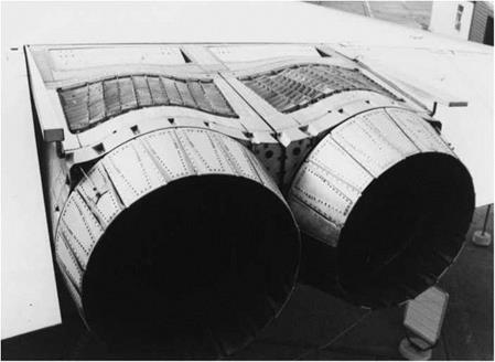
Fig. 6.32 The variable-geometry outlet nozzles and the louvres of the thrust reversers are seen in this view of the hot end of the Concorde engine installation

At supersonic speeds, with the simple tubular ‘pitot’ type air intake, the flow has to decelerate through a detached normal shock. This results in considerable losses. Much higher efficiency is obtained if the flow is compressed through a series of oblique shocks. Figure 6.33 shows the intake system used on Concorde. The flow is compressed, and the speed reduced through a series of oblique shock waves, a region of shockless compression, and a weak normal shock. The intake geometry has to be varied in flight to match the Mach number of the approaching flow, and to capture the shock. Movable ramps are used for this purpose. Extra intake area is provided for flight at low sub­sonic speeds. Intakes of this type are classified as two-dimensional, and are used on a number of combat aircraft.

Note that part of the compression is provided by the shock wave produced by the wing. This shows the importance of integrating the design of the engine intake with that of the wing.

An alternative axi-symmetric arrangement is to use an axially movable or variable-geometry central bullet, as shown in Fig. 6.39. In the design depicted in this drawing, a combination of external and internal shock waves is shown. Axi-symmetric bullet-type intakes are used on the SR-71 Blackbird shown in

Подпись: Thrust

Propulsion for supersonic flight Propulsion for supersonic flight

Propulsion for supersonic flightBoundary layer Movable ramp

Подпись: SubsonicOblique

shock waves shock system flow

Fig. 6.33 A two-dimensional type variable geometry intake for supersonic flight

This form of intake is used on Concorde. In supersonic cruise, the air is slowed down to subsonic speed and compressed through a series of oblique shocks and a region of shockless compression produced by the curved movable ramp (a) Subsonic configuration (b) Supersonic configuration

Fig. 6.40. Aircraft with side intakes may use two half axi-symmetric intakes, as on the F-104 (Fig. 8.8), or quarter versions, as on the F-111 (Fig. 6.35).

The design of supersonic intakes is an extremely complex subject, and further information will be found in Seddon and Goldsmith (1985) and Kuchemann (1978).

Although the variable geometry intake reduces losses due to shocks, it results in an increase in weight and complexity. A variety of fixed and variable intakes may be seen on modern combat aircraft. The Tornado (Fig. 3.15), and F-14 (Fig. 8.2) use two-dimensional variable geometry intakes, whereas a simpler fixed pitot type is used on the F-16.

The choice depends largely on the main combat role intended. The Tornado is designed for multi-role use which includes sustained supersonic flight, so that efficient supersonic cruising is necessary.

In the interests of avoiding strong radar reflections, ‘stealthy’ aircraft may have unusual inlet and exhaust arrangements, as shown in Fig. 6.34. These are not necessarily aerodynamically optimised.

Fig. 6.34 Design for stealth

On the F-117A stealth fighter/bomber the intakes are concealed behind a radar absorbent grid. Thin two-dimensional exhaust nozzles are used, with the lower lip protruding so as to conceal the exhaust aperture. The use of flat-faceted surfaces helps to reduce the radar signature. The resulting shape, which has the appearance of being folded from a sheet of cardboard, must have presented a considerable challenge to the Lockheed aerodynamicists