Category Aircraft Flight

Best speed for economy and range

As we mentioned earlier in this chapter, the ‘best’ operating speed for an air­craft depends on the particular role it is designed to fulfil. If the object of the exercise is to carry passengers from A to B, then an important consideration is the amount of fuel used, which will normally be kept close to the minimum for the job in hand. Achievement of maximum range is a very similar problem. In this case instead of having a requirement to travel a fixed distance using the minimum amount of fuel, we need to travel the maximum distance for a given fuel load.

If we take a very simplified view of things, and assume constant engine efficiency, the requirement, both for best range and economy, is that the total amount of work done as the aircraft moves from A to B should be kept as low as possible.

The total work done is the force times the distance through which it is moved. In this case the only force which is moved through a significant distance is the drag (Fig. 7.6) and the distance through which it is moved is equal to the distance the aircraft flies between its starting and stopping points. Thus, we can see that for the best economy, on this simplifed view, the aircraft should be

Fig. 7.6 Economic cruise

Total energy expended as aircraft flies from A to B is equal to the drag times distance flown

flown at its minimum drag speed. It should be noted that this speed will change during the flight as the aircraft weight will reduce as fuel is used up.

Approximately at least, changes in wing loading and altitude only alter the speed at which the minimum drag occurs and not its value. Thus as far as the airframe is concerned the total energy which must be expended for a given journey is independent of both wing loading and altitude.

We know from Chapter 6 that in reality engine efficiency is not constant and that the different types of powerplant have their distinctive characteristics. Consequently we shall consider the problems of operating the complete air- frame/engine combination for optimum economy under headings appropriate to the type of installed powerplant.

Supercritical aerofoils for transonic flow

The conventional section, as we have seen, relies heavily on the leading-edge suction peak to develop lift. This means that most of the lift is developed at the front of the section and relatively little at the rear. One way of improving the situation, without incurring the penalty of high local Mach numbers, is to ‘spread’ the load peak and load up the rear of the aerofoil thus producing the type of distribution shown in Fig. 9.5, the so-called ‘roof top’ distribution.

The way in which this is done is to reduce the camber at the front of the aerofoil (the camber may even be negative here) and to increase it towards the rear. This gives the typical section shown in Fig. 9.5. In this way the locally high Mach numbers and strong shock waves associated with a conventional section can be avoided.

In Chapter 5 we saw that a region of shock-free compression can exist in a flow provided Mach lines drawn within the compressive region do not con­verge. An example of this was given in Fig. 5.15 where a shock-free (so-called isentropic) compression region is shown near a smooth corner on a surface. The same technique can be used to avoid the formation of shock waves in the recompression of the flow over a supercritical aerofoil.

In this case the process is complicated by the existence of the subsonic flow outside the local supersonic ‘patch’. Complex wave reflections will occur both at the sonic boundary between the two areas as well as from the aerofoil

Pressure lower than surrounding atmosphere

Pressure greater than surrounding atmosphere

Fig. 9.5 ‘Roof top’ pressure distribution

Local surface Mach number is close to 1.0 between A and B

Fig. 9.6 Shock-free recompression

Weak compression waves in supersonic region reach sonic boundary before forming shock wave

surface itself (Fig. 9.6). The local surface slope in the compression region must therefore be carefully designed to suppress any tendency for the compressive wave to coalesce into a shock wave within the supersonic ‘patch’.

In Fig. 5.15 the formation of the shock wave away from the surface is inevitable because the flow is supersonic everywhere. The waves generated in the supersonic region over our aerofoil can, however, reach a region of sub­sonic flow before they run together, if we get the design right. In this case no shock wave will be formed.

The process of design is much more complicated than may appear from the above account. While a satisfactory solution may be obtainable for a single design point it will be necessary to ensure that the off design flow is both stable and not subject to large drag rises. Careful design will also be required to prevent adverse shock/boundary layer interactions in the off design condition. Because of this such aerofoils do not usually run with entirely shock-free recompression but the supersonic region of flow is terminated by a near normal

atmosphere

Fig. 9.7 Peaky pressure distribution

Flow on top surface is supersonic up to weak shock wave shock wave of low strength. This feature may well improve buffet behaviour which will be discussed shortly.

With improved computational methods the design of supercritical aerofoils is advancing rapidly. Figure 9.7 shows the pressure distribution over a modern supercritical aerofoil similar to that used on the A320 Airbus. A large area of supersonic flow is employed over the top surface ending with an almost shock – free compression so that losses are kept low. This means that the local loading in this area can be higher, leading to a somewhat more ‘peaky’ distribution than the ‘roof top’ distribution shown in Fig. 9.5.

The aerodynamic problems involved in designing supercritical sections with suitable ‘off-design’ performance are severe. They are an example of one area in which the use of computers in the solution of the basic equations of the air flow has produced dramatic results.

Aircraft control at low speed

Control problems at low speed stem from three major factors; weak aero­dynamic control forces, the danger of provoking a stall, and the immersion of control surfaces in a slow-moving separated or wake flow, which may be highly turbulent.

The weakness of the aerodynamic control forces is one of the major factors limiting the minimum speed of short take-off and landing (STOL) aircraft. Very large surfaces must be installed. Note the very large fin in the photograph of the C-17 shown in Fig. 10.20. Such large surfaces, however, represent a source of drag and weight, and detract from the cruise performance. In gliders, where cruise performance is all important, the tail surfaces are normally very small.

At low speeds, the wing is fairly close to its stall angle of attack. Downward deflection of an aileron could cause the wing tip to stall, and drop instead of rising, thus giving rise to control reversal, as well as the possibility of provok­ing a spin (described in Chapter 12). The geared aileron in which the down­going surface moves less than the rising one can help to overcome this problem, but the use of spoilers for low speed roll control is sometimes a better solution.

For very low speed flight, and vertical take-off and landing (VTOL), the aerodynamic forces are too small to be used for control purposes. Some form

Fig. 10.20 The C-17 has a STOL (short take-off and landing) capability

The large vertical tail surface is necessary to provide stability and control at low speeds. The very high mounting position of the horizontal tail surface helps to keep it out of the wake of the wing at high angles of attack

of reaction control has to be used, as on the Harrier, where ‘puffer’ jets are located at each wing tip, and on the nose and tail, as illustrated in Fig. 10.21. The jets are fed by compressed air from the engines. A reaction control arrange­ment is also used for controlling and stabilising spacecraft.

When an aircraft is flown under reaction control, its safety is totally depend­ent on an uninterrupted supply of compressed air, which makes the idea of civil VTOL aircraft, other than helicopters, unattractive to civil airworthiness authorities. However, operational experience with the Harrier indicates that because of the low speeds involved, serious accidents on landing and take-off are, if anything, less frequent than with conventional aircraft.

The spin

We have previously mentioned the control problems which may be caused by the stall occurring at the wing tip before the root. If the aircraft is not flying perfectly symmetrically when such a stall occurs, one tip will stall before the other resulting in a rolling moment because of the reduction of lift on the stalled tip. This will also be accompanied by a yawing moment because of the locally increased drag (Fig. 12.14). The result of this is that the aircraft will enter a spiral path and is then said to be spinning. Figure 12.15 shows how the aircraft can get ‘locked’ into the spin. Although the rising wing is at a lower angle of attack its lift coefficient may be the same as the stalled falling wing which is operating ‘over the hump’ of the lift curve. Thus there will be no over­all rolling moment and the rolling rate becomes constant.

The overall motion is a mixture of roll, sideslip and yaw (Fig. 12.16). If the spin is steep, roll is more important than yaw. If it is flat the reverse is true as can also be seen from Fig. 12.17.

The presence of the rolling component causes the incidence of the stalled wing to increase and the unstalled wing to decrease, thus strengthening the basic aysmmetry of the flow which ‘locks in’ as described above. Similarly the yawing motion will cause the fin to supply a yawing moment which balances that due to the stalled wing. The yaw then settles at a steady rate.

Fig. 12.14 Asymmetric stall

Stall on one wing results in roll and yaw

Fig. 12.17 Steep and flat spins

In steep spin rotation is primarily in roll, in flat spin primarily in yaw

Fig. 12.18 Effect of mass distribution on spin

Masses at nose and tail tend to move outwards under rotation thus flattening the spin

Once established, the spin will thus persist and in some cases correction can be difficult. For example recovery is not possible from an inverted spin on many swept-wing fighters.

The inertial properties of the aircraft have an important bearing on its spin­ning characteristics. Figure 12.18 shows that the spin will tend to be flattened by the presence of mass concentrations towards the nose and tail.

Spin recovery, like recovery from a simple stall, requires the separated flow over the stalled wing to be reattached. In the spin this is done by first removing the yaw by applying rudder in the opposite sense to the direction of rotation, and when the aircraft is established in a steady dive, pulling out by means of the elevators. For difficult cases other techniques, such as a tail parachute, may be employed.

Recommended further reading

Abzug, M. J. E. and Larrabee, E., Airplane stability and control: a history of the tech­nologies that made aviation, Cambridge University Press, Cambridge, 1997, ISBN 0521809924.

Cook, M. V., Flight dynamics principles, Arnold, London, 1997, ISBN 0340632003. A good standard undergraduate text.

Nelson, R. C., Flight stability and automatic control, 2nd edn, McGraw Hill, Boston, Mass., 1998, ISBN 0070462739. An integrated treatment of aircraft stability, flight control, and autopilot design, presented at an accessible mathematical level, using standard terminology and nomenclature.

Nickel, M. W., Tailless aircraft in theory and practice, (Eric M. Brown translator), Edward Arnold, London, 1994, ISBN 1563470942. A well known standard work which originally appeared in German.

Other methods of lift generation

Controlled separation – conical vortex lift

On aircraft with straight unswept wings, flow separation results in a poor ratio of lift to drag, and buffeting due to instability of the flow. However, if the wings are swept back at a sharp angle, the separated flow will roll up into a pair of stable cone-shaped vortices, as shown in Fig. 1.21. Unlike the bound vortex of a conventional wing, which merely represents a circulatory tendency, these are real vortices; swirling masses of air, as in a whirlwind.

The presence of these leading-edge conical vortices is revealed in Fig. 1.20 by the vapour condensation clouds that they produce. Their influence is also evident in the surface flow patterns shown in Fig. 1.22.

This type of separated vortex flow represents an alternative method of lift generation. The air speed in the vortex is high, and so the pressure is low. Thus,

Other methods of lift generation

Fig. 1.20 Conical vortex lift

The strong conical vortex that forms over the leading edge of a slender delta wing can sometimes be seen by the vapour condensation that it produces. Because of the high angle of attack required on landing and take-off, the nose of concorde had to be lowered to enable the pilot to see the runway (Photo courtesy of British Aerospace (Bristol))

lift is still produced by exposing the upper surface to a lower pressure than the underside, but the low pressure on the upper surface is now produced mainly as a consequence of the vortex motion above it.

At low angles of attack, the flow on a slender delta or highly swept wing may remain attached, and lift can be generated in the conventional way. As separation takes place, and the vortices form, an extra contribution to lift occurs, as shown in Fig. 1.23. It will be seen that the CL to angle of attack curve is not a straight line.

The slender delta-winged Concorde was designed to fly with separated conical vortex flow in normal flight conditions. The leading edge is sharp to encourage leading edge separation at moderate angles of attack.

This conical vortex flow may be thought of as being a form of controlled separation. When lift is generated in this way, the wing will not stall in the con­ventional sense, and the lift will continue to increase for angles of attack up to 40 degrees or so. At higher angles, the vortices start to break down, and the lift falls off.

Other methods of lift generation

Fig. 1.21 Controlled separation on a slender delta

The flow separates along the leading edges and rolls up into a pair of conical vortices. The low pressure in the vortices contributes to the production of lift

Other methods of lift generation

Fig. 1.22 Surface flow patterns on a delta and a highly swept wing

The model wings have been painted with a suspension of white powder (titanium dioxide) in paraffin. The scouring effect of the separated leading edge conical vortices can be seen

Other methods of lift generation

Fig. 1.23 Variation of lift coefficient with angle of attack for a slender delta

At high angles of attack, the leading edge vortices make a significant extra ‘non-linear’ contribution to lift

Slender delta and highly swept wings have advantages in supersonic flight, as we shall describe in later chapters. This method of lift generation is, there­fore, most frequently used on aircraft designed for supersonic flight. Separated vortex flow has, however, kept generations of paper darts flying across class­rooms; a fact that demonstrates that this is also a suitable method of producing lift; even at low subsonic speeds.

Interestingly, a slender delta aircraft, based no doubt on the paper dart, was proposed in the nineteenth century; it was to be propelled by a steam jet!

Separated vortex lift is sometimes used in conjunction with conventional lifting surfaces to prevent stalling locally. A strake in front of a fin or tailplane helps to prevent stalling of these surfaces during manoeuvres especially at low speeds. A fin strake may be seen on the Dash-8, in Fig. 13.4. The design of wings for separated vortex flow is dealt with in more detail in the next chapter.

More boundary layer problems on swept wings

When air flows over a swept wing, the chordwise component of velocity changes in much the same way as the flow speed over an unswept wing, but the spanwise component remains more or less constant. This means that the local flow angle varies across the chord, and streamlines are consequently curved. Also, since the flow velocity varies with depth through the boundary layer, the amount of curvature will vary through the layer. This and other complex distorting effects hasten the transition to turbulence and increase the level of turbulence after transition. A further problem is that at the leading edge, the air is not brought to rest along a stagnation line as on a straight wing. On a swept wing, it is only the normal component that slows down to zero when the flow

meets the leading edge. The spanwise velocity component is little changed and with a strong spanwise component of velocity, there can be a turbulent boundary layer right at the leading edge.

The above features mean that on swept wings there is often little or no lami­nar boundary layer flow, and this creates a penalty in terms of the amount of surface friction drag generated. One way of improving the situation is to suck the boundary layer away through slots or small holes in the surface, as described previously. A significant benefit can be obtained even if only a small portion near the leading edge is made porous, since this can enable a region of laminar layer to become established. The reduction in drag thus obtained might be enough to offset the cost and complexity of such an approach. The technology for producing very small holes economically now exists, and there is renewed research interest in such boundary layer suction systems.

Mach waves and the Mach cone

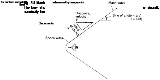
Figure 5.8 shows that the bow shock wave becomes progressively more oblique with increasing distance from the aircraft. As its angle to the free stream flow direction reduces so the shock weakens and the changes in pressure, density, flow direction etc. become less.

At very large distances from the aircraft the wave becomes very weak indeed, like a sound wave. The angle it makes with the free stream direction tends to a particular value known as the Mach angle (Fig. 5.9) and the very weak shock wave is known as a Mach wave. When this happens the velocity component at right angles to the wave is equal to the speed of sound.

The idea of the Mach wave as a line is very important in supersonic flow as it establishes the region of the flow field which can be influenced by a given point on the aircraft surface. For example, if we consider the supersonic flow past a surface (Fig. 5.10), we can imagine a very small irregularity at point A generating a very weak local shock wave, or Mach wave. The flow up­stream of this Mach wave will be uninfluenced by the presence of the surface irregularity.

Подпись: Flow unaffected

Mach waves and the Mach cone

Mach waves and the Mach coneFlow behind Mach wave

Fig. 5.10 Surface irregularity

In supersonic flow only the area downstream of the Mach wave will be influenced

The angle of the Mach wave to the local stream direction depends only on the upstream Mach number (Fig. 5.9); the Mach wave becomes more swept back as the Mach number increases. Only the downstream flow is affected by the change in geometry. Had the flow been subsonic then the whole of the flow field would have been altered.

For a three-dimensional flow the region which can be influenced by a par­ticular point is given by a surface made up from Mach lines, and this is known as a Mach cone (Fig. 5.11).

Mach waves and the Mach cone

Fig. 5.11 Mach cone

The effect of the irregularity can only be felt within the 3-D Mach cone which has a surface made up of Mach lines

Gas turbine development

The idea of using a gas turbine to produce jet propulsion was developed quite independently by Whittle in England and von Ohain and others in Germany in the 1930s. Neither Whittle nor the other pioneers actually invented the gas turbine; the concept had been around for some time. Their genius lay in realis­ing that such an apparently unpromising and inefficient form of engine would provide the basis for high speed and high altitude flight.

Whittle filed his original jet-propulsion patent in 1930, and his experi­mental engine first ran in April 1937. Von Ohain’s records were lost during the war, but it is thought that a von Ohain/Heinkel engine actually ran in the previous month. This engine was however a preliminary experimental arrange­ment running on gaseous hydrogen.

The first jet-engined aircraft was the Heinkel He-178 shown in Fig. 6.17. Using a von Ohain engine, its maiden flight was on 27th August 1939, some 21 months before that of the British Gloster/Whittle E28/39.

Some gas turbines use a centrifugal compressor as shown in Fig. 6.18. This form was used on early British jet engines and is similar to the type used in superchargers. Air enters the rotating disc at the centre and is spun to the outside at increased pressure and a considerable whirl speed. A diffuser down­stream, consisting of fixed curved blades or passages, is used to slow the flow down by removing the whirl component. The reduction in speed is accom­panied by a further rise in pressure.

Both the Whittle and the von Ohain engines used a centrifugal compressor, but by 1939 rival British and German teams were already working on axial compressors which offer higher efficiency and reduced frontal area.

As shown in Fig. 6.19, an axial compressor consists of a series of multi – bladed fans separated by rows of similar-looking fixed stator blades. The mov­ing blades are used to increase the pressure and density rather than the speed. The stator blades remove the swirl and produce a further pressure rise.

The rise in pressure obtainable through a single row or stage is not as great as for a centrifugal compressor, and many stages are required. Despite a trend to higher overall pressure ratios, modern engines are able to use fewer stages because of improved design.

The earliest successful turbo-jet with an axial compressor was the Junkers Jumo 004 which was developed by a team led by the little-known Anselm Franz. In 1942 this engine was used to power the Messerschmitt Me 262, the

Gas turbine development

Fig. 6.18 A centrifugal compressor

Air enters at the centre, and is spun to the outside


Main shaft

Intake casing Stator vane Rotor blade drive from turbine

Gas turbine development

Fig. 6.19 An axial compressor

Many rows of alternate moving ‘rotor’ and fixed ‘stator’ blades are required (Illustration from Rolls-Royce The Jet Engine)


Turbine

driving

compressor


Turbine

driving

propeller


Gearbox


Gas turbine development

Подпись: DriveПодпись:Centrifugal

compressor

Fig. 6.20 A turbo-prop engine

The design illustrated uses centrifugal compressor stages. For turbo-prop engines, it is still common practice to use at least one centrifugal compressor stage.

The gearbox and accessory drives represent a significant proportion of the total engine weight (Illustration courtesy of Rolls-Royce pic)

world’s first jet-propelled combat aircraft (Fig. 2.18). The Jumo engine, with its axial compressor and annular combustion chamber, was much more like a modern engine than the Whittle or von Ohain engines, and was developed quite independently, with no knowledge of Whittle’s work.

Whittle’s heroic efforts are well documented in his book Jet (1953) and in a later book by Golley (1987). A full account of the early jet engines is given by Glyn Jones in The Jet Pioneers (1989).

Although the axial compressor is always used for large turbo-jet engines, smaller engines and those designed for turbo-prop propulsion often have at least one centrifugal stage (see Fig. 6.20, and Fig. 6.21). The centrifugal compressor is simpler, and considerably cheaper than the axial type, and in applications such as helicopter propulsion, the increased diameter is of little significance.

Rate of climb

When we consider rate of climb we are primarily concerned with increasing the potential energy of the aircraft as quickly as possible, and we will assume that we do not wish to change the forward speed at the same time so that the kinetic energy remains unaltered in the steady climb (Fig. 7.16).

Horizontal velocity

Rate of increase in potential energy
climb velocity x aircraft weight

Fig. 7.16 Rate of climb

Increased potential energy must be provided by excess engine power over that required for level flight

If we have a piston-engined aircraft, the required operating conditions are now quite clear. All we need to do is to make the difference between the power produced by the engine and the power required to overcome the drag as large as possible. This will provide the largest possible excess power to increase the aircraft potential energy at the highest possible rate (Fig. 7.17).

If we make the simplifying assumption that the engine power is constant, then we should operate at the forward speed corresponding to the minimum required power – the same speed that we found was required for maximum endurance in level flight.

For a turbo-jet engine, the power increases with speed and so we shall, once more need to compromise between the engine and airframe requirements. To get the maximum excess power we must operate at a speed in excess of the minimum required power speed (Fig. 7.18).

RATE OF CLIMB 211

Fig. 7.17 Maximum rate of climb – piston engine

Because available power is nearly constant, aircraft speed for best rate of climb occurs near the speed for minimum required power

Speed

Fig. 7.18 Maximum climb rate – jet engine

Because engine power increases with speed, maximum power for climb is obtained at a speed in excess of minimum power required speed and minimum drag speed

Some concluding remarks

So far our discussion of aircraft with a subsonic cruising speed in the transonic range has been concerned a great deal with transport aircraft which are not required to indulge in violent manoeuvres and whose cruising altitude can, within the restrictions imposed by air traffic control, be selected to give the most economical performance. Before we leave the subject, it is, however worthwhile to remind the reader that other types of transonic aircraft also exist, with different design requirements.

One such aircraft is shown in Fig. 9.2. The Hawk is, for example, required to fly transonically at low altitude and to carry a wide range of under-wing mounted missiles and bombs for ground attack purposes. The requirement of high manoeuvrability means that a relatively stiff wing of restricted span is required. Another example of a military transonic aircraft having specialised operational requirements is the Harrier, which has been previously mentioned. The use of jet lift derived from the engine nozzles means that a comparat­ively small wing can be used since the landing requirement is no longer such a powerful influence on the design. The use of downward directed nozzles also dictates the high wing configuration.

Recommended further reading

Jenkinson, L. R., Simpkin, P. and Rhodes, D., Civil jet aircraft design, Arnold, 1999, ISBN 0340631708. An excellent account of the practicalities of transonic transport design.