Category Airplane Stability and Control, Second Edition

Aileron-Reversal Flight Experiences

The World War II Japanese Zero fighter airplane had very low roll performance at high airspeeds, due to wing twist. U. S. combat pilots took advantage of this weakness. They avoided circling combat and established high-speed, single-pass techniques. At high airspeeds, the roll rates of the U. S. airplanes could not be followed by the Zeros, which were operating near their aileron-reversal speeds.

The role of aileron reversal due to torsional flexibility on missions of the Boeing B-47 Stratojet is mentioned in Chapter 3, “Flying Qualities Become a Science.” Boeing engineers attempted to deal with the roll reversal problem when designing the B-47 (Perkins, 1970). They knew there was a potential roll reversal problem since the B-47’s wing tips deflected some 35 feet between maximum positive and negative loads. Using the best approach known at the time, strip integration, torsional airloads were matched to stiffness along the wing span. This method predicted an aileron-reversal speed well above the design limit speed. Unfortu­nately, this approach didn’t take into account wing bending due to aileron loads. Wing bend­ing on long swept wings results in additional twist. The actual aileron-reversal speed turned out to be too low for low-altitude missions. Quoting from Perkins’ von Karman lecture:

A complete theoretical solution to the problem was undertaken at the same time [as the strip method application] and due to its complexity and the lack of computational help, arrived at the right answer two years after the B-47 first flew. A third approach to the problem was undertaken by a few Boeing experimentalists who put together a crude test involving a makeshift wind tunnel and a steel sparred balsa wood model that was set on a spindle in the tunnel with ailerons deflected and permitted freedom in roll. The tunnel speed was increased until the model’s rate of roll started to fall off and then actually reverse. This was the model’s aileron reversal speed and came quite close to predicting the full-scale experience. The test was too crude to be taken seriously and again results came too late to influence the design of the B-47.

According to William H. Cook, the B-47 not only had excessive wing torsional deflection due to aileron forces, but also slippage in the torsion box bolted joints. The wings would take a small permanent shape change after every turn. These problems led to a test of spoiler aileronsona B-47, although the production airplane wasbuilt with normal flap-type ailerons.

Decoupled Controls

Airplane stability augmentation must be rethought when designers choose to add direct normal and side force control surfaces. For example, with direct lift control through a fast-acting wing flap, pitch attitude can be controlled independently of the airplane’s flight path, and vice versa. The utility of such decoupled controls for tracking, defensive maneuvers, and for landing approaches is reviewed by David J. Moorhouse (1993).

20.4 Integrated Thrust Modulation and Vectoring

An airplane’s propulsion system can be integrated into a stability augmentation system that uses aerodynamic control surfaces. The total system would operate while the airplane remains under the control of the human pilot, qualifying as a stability-augmentation system rather than as an automatic flight control system.

For comparison, the previous coverage of propulsion systems in this book included:

Chapter 4 the effects of conventional, or fixed-configuration, propeller-, jet-, and rocket-propulsion systems on stability and control;

Chapter 10, Sec. 8 thrust vector control to augment aerodynamic surfaces in supermaneuvering;

Chapter 11, Secs. 14 and 15 propulsion effects on modes of motion and at hypersonic speeds;

Chapter 12, Sec. 1 carrier approach power compensation systems, for constant angle of attack approaches;

Chapter 20, Sec. 11 Propulsion-controlled aircraft, designed to be able to return for landing after complete failure of normal (aerodynamically implemented) control systems.

Depending on the number of engines under control, thrust modulation and vectoring systems can supply yawing, pitching, and rolling moments, as well as modulated direct forces along all three axes. Thus, thrust modulation and vectoring integrated into a stability – augmentation system can augment or replace the aerodynamic yawing, pitching, and rolling moments provided by aerodynamic surfaces. The situation is similar to aircraft like the Space Shuttle Orbiter, which carries both aerodynamic and thruster controls. However, in the context of stability augmentation, thrust modulation and vectoring would be used normally at the low airspeeds of approach and landing, rather than in space.

While in principle thrust modulation and vectoring can take the place of aerodynamic control surfaces at the low airspeed where the aerodynamic surfaces are least effective, it is reasonable to ask whether thrust stability-augmentation systems could satisfy flying qualities requirements. In a simulation program at DERA, Bedford (Steer, 2000), integrated thrust vector control was evaluated at low airspeeds on the baseline European Supersonic Commercial Transport (ESCT) design. The nozzles of all four wing-mounted jet engines were given both independent pitch and yaw deflections, providing yawing, pitching and rolling moments. Nozzle deflections were modeled as first-order lags. Conventional pitch rate, pitch attitude, velocity vector roll rate and sideslip command control structures were programmed.

Pitch control by thrust vectoring at approach airspeeds was as good as aerodynamic or elevon control, for a reason peculiar to the very low wing-aspect-ratio ESCT configuration. That is, the airplane has high induced drag at approach angles of attack, requiring large levels of thrust to maintain the glide path, thus making available large pitching moments with thrust deflection. Low airspeed roll and sideslip thrust vector control were positive and suitably damped but did not satisfy MIL-STD-1797A criteria.

Catching Up to the Wright Brothers

Two public demonstrations of perfectly controlled mechanical flight in 1908 by Wilbur Wright in France and by Orville Wright in the United States were clarion calls to the rest of the aeronautical community to catch up with and surpass their achievements. The airplane builders – Curtiss, Bleriot, Levavasseur, the Voisins, Farman, Bechereau, Esnault – Pelterie, and others – responded; by 1910 they flew faster and almost as well; by 1911 they flew better. However, even after these momentous achievements, neither the Wrights nor their competitors still had any real understanding of aerodynamic theory.

1.2 The Invention of Flap-Type Control Surfaces and Tabs

Flap-type control surfaces, in which a portion of the wing or tail surface is hinged to modify the surface’s overall lift, are at the heart of airplane control. Airplanes designed to fly at supersonic speeds often dispense with flap-type longitudinal controls, moving the entire horizontal surface. Also, some airplanes use spoiler-type lateral controls, in which a control element pops out of the wing’s upper surface to reduce lift on that side. Aside from these exceptions, flap-type controls have been the bread-and-butter for airplane control since a few years after the Wright brothers.

It was in 1908 that the aviation pioneer Glenn Curtiss made the first flight of his June Bug airplane, which was equipped with flap-type lateral controls. This was an early, if not the first, advance in lateral control beyond the Wright brothers’ wing warping. The Curtiss lateral controls were attached to the interplane struts between the biplane wings and were all-moving. Curtiss evidently saw them as lateral trim devices, since the wheel was connected to the rudder. The French called the flap-type lateral controls ailerons – little wings – and the name has persisted in the English language. The Germans call them querrudern, or lateral rudders.

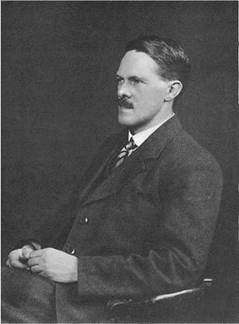
The first true flap-type aileron control appears to have been on the French Farman biplane a year or two later. An aerodynamic theory for flap-type controls was needed, but it wasn’t until 1927 that Hermann Glauert (Figure 1.2) supplied this need. Control surface tabs are small movable surfaces at the trailing edge, or rear, of a flap-type control. Tabs generate aerodynamic pressures that operate with a long moment arm about the control surface hinge line. Tabs provide an effective way to deflect main control surfaces in a direction opposite to the deflection of the tab itself relative to the main surface.

Catching Up to the Wright Brothers

Figure 1.2 Hermann Glauert (1892-1934). In Glauert’s short career he made important airplane stability and control contributions, in control surface, downwash, airfoil, wing, and propeller theory, and in the equations of motion. (From Obit. Notices of Fellows of the Royal Soc., 1932-1935)

The tab concept is due to the prolific inventor Anton Flettner, who first applied it to steamboat rudders. One may still find references in the literature to “Flettners,” meaning tabs. Flettner received a basic German patent for the tab in 1922. This was for its application to aeronautics. Flettner’s patent includes a description of a spring tab device (see Chapter 5), which was promptly forgotten. Glauert’s aerodynamic theory for flap-type controls was extended to the tab case in 1928 by W. G. Perrin.

Direct-Thrust Moments in Yaw

For a multiengine airplane whose engines are mounted on the wings, when all engines are running and developing about the same power, there is no unbalanced yawing moment due to power. Failure of a wing-mounted engine of course sets up a thrust-caused yawing unbalance that must be counteracted by an equal and opposite aerodynamic yawing moment. The more engines on a multiengine airplane, the less effect will the failure of a single one have on yawing moments. Flight crews of Boeing B-29 and B-50 four-engine airplanes had the strange experience of losing engines during normal cruise flight and being unaware of it for many seconds. RPM for the dead engine would drop very little at first because of propeller windmilling. The directional stability of both airplanes was high enough to keep the ships close to course, initially.

Current Boeing Company design practice requires that a twin-engine jet transport be able to continue a climbout after takeoff, rudder-free, with one engine failed. This accounts for the generously sized vertical tails on the 737, 757, 767, and 777 models.

Safety Issues in Fly-by-Wire Control Systems

Although fully fly-by-wire flight control systems have become common on very fast or large airplanes, questions remain as to their safety. No matter what level of redundancy is provided, one can always imagine improbable situations in which all hydraulic or electrical systems are wiped out. Because of the very high-power requirements of hydraulic controls, their pumps are driven by the main engines. This makes necessary long high-pressure tubing runs between the engines and the control surfaces. The long high-pressure hydraulic lines are subject to breakage from fatigue; from wing, tail, and fuselage structural deflections; and from corrosion and maintenance operations.

The dangers of high-pressure hydraulic line breakage or leaking, with drainage of the system, could be avoided at some cost in weight and complexity with standby emergency electrically driven hydraulic pumps located at each control surface. An additional safety issue is hydraulic fluid contamination. Precision high-pressure hydraulic pumps, valves, and actuators are sensitive to hydraulic fluid contamination.

In view of rare but possible multiple hydraulic and electrical system failures, not to mention sabotage, midair collisions, and incorrect maintenance, how far should one go in providing some form of last-ditch backup manual control? Should airplanes in passenger service have last-ditch manual control system reversion? If so, how will that be accomplished with side-stick controllers?

In the early days of hydraulically operated controls and relatively small airplanes the answer was easy. For example, the 307 Stratoliner experience and other hydraulic power problems on the XB-47 led Boeing to provide automatic reversion to direct pilot control following loss in hydraulic pressure on the production B-47 airplanes. Follow-up trim tabs geared to the artificial feel system minimized trim change when the hydraulic system was cut out. Also, when hydraulic power was lost, spring tabs were unlocked from neutral.

Manual reversion saved at least one Boeing 727 when all hydraulic power was lost, and a United Airlines Boeing 720 made a safe landing without electrical power. The last-ditch safety issue is less easily addressed for commercial airplanes of the Boeing 747 class and any larger superjumbos that may be built. Both Lockheed L1011 and Boeing 747 jumbos lost three out of their four hydraulic systems in flight. The L1011 had a fan hub failure; the 747 flew into San Francisco approach lights. A rear bulkhead failure in Japan wiped out all four hydraulic systems of another 747, causing the loss of the airplane.

In another such incident the crew, headed by Delta Airlines Captain Jack McMahan, was able to save a Lockheed 1011 in 1977 when the left elevator jammed full up, apparently dur­ing flight control check prior to takeoff at San Diego (McMahan, 1983). There is no cockpit indicator for this type of failure on the 1011, and the ground crew did not notice the prob­lem. McMahan controlled the airplane with differential thrust to a landing at Los Angeles. This incident was a focus of a 1982 NASA Langley workshop on restructurable controls.

Workshop attendees discussed the possible roles of real-time parameter identification and rapid control system redesign as a solution for control failures.

Thus, although fully mechanical systems can also fail in many ways, such as cable misrig or breakage, jammed bellcranks, and missing bolts, questions remain as to the safety of modern fly-by-wire control systems. The 1977 Lockheed 1011 incident, a complete loss in hydraulic power in a DC-10 in 1989, and other complete control system losses led to the interesting research in propulsion-controlled aircraft described in Sec. 20.11.

Changing Spin Recovery Piloting Techniques

The 1916-era prescription for spin recovery, “thrust the control stick forward and apply rudder in the sense opposed to the rotation,” held good for many years afterwards. It was not until airplane mass distributions changed appreciably from those of early airplanes that not only design criteria, but also pilot manipulations, changed for spin recovery.

One interesting change has to do with airplanes with heavy weights along their wings. While early four-engine bombers and transports are in this category, these airplanes are not expected to be spun, even unintentionally, and indeed could fail structurally in spins. Modern light twin airplanes fall somewhat into the wing-heavy weight distribution category, and appropriate spin recovery procedures are less academic. The key result is that down-elevator

Changing Spin Recovery Piloting Techniques

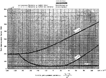
Figure 9.5 NACA tail design requirements for satisfactory spin recovery of personal-owner-type airplanes. The symbol і is the airplane relative density factor, with typical values of 4.0 forthe Cessna 150 and 8.6 for the Grumman/American Yankee. (From Neihouse, NACA TN 1329, 1947)

becomes of primary importance in spin recovery, reducing greatly the need for opposite rudder.

In at least one case, this finding was ignored in the design of a popular light twin airplane (Abzug, 1977). Nominal down-elevator travel of the Rockwell Aero Commander is small, at only 10 degrees. In addition, the elevator stops are located in the cockpit area, rather than at the control surface. This allows control cable stretch at spin attitudes and airspeeds to reduce available down-deflection to an estimated 3 degrees, almost certainly insufficient for spin recovery.

An equally dramatic and significant change in pilot spin recovery techniques is required by the opposite extreme in loadings, or heavy weights along the fuselage. For this loading, representative of all modern thin-wing jet fighters, aileron with the spin becomes the primary spin recovery control, supplemented by the usual rudder against the spin. One of this book’s authors (Abzug) briefed the spin test pilot for the Douglas XF4D-1 Skyray at a time when the aileron-with recovery technique had just become known to engineers. Spin tunnel graphs and tables seemed to be getting nowhere in the pilot’s ready room at Edwards Air Force Base. Then the pilot perked up. “I see,” he said, “Ailerons with the spin will give anti­spin yawing moments because of adverse yaw. Adverse yaw must be large because of the low-aspect-ratio wing” [aspect ratio was just 2.0]. The matter was allowed to rest there, since as long as the controls were to be applied correctly, the misunderstanding would not matter.

Although ailerons with the spin is an accepted spin recovery technique for heavy fuselage loadings and modern power controls ensure that the controls can be applied, spin recovery problems with these airplanes are far from overcome. Heavy fuselage loadings also bring about oscillatory spins and the rather wild departure motions discussed in a later section.

Spin oscillations can be so extreme as to cause erect spins to go inverted or to confuse the pilot as to the actual direction of spin rotation.

Trim Changes Due to Compressibility

One compressibility effect on airplane stability and control that was not done away with by wing sweepback or thin wings was the longitudinal trim change when accelerating or decelerating through the speed of sound, or Mach 1. This was a much more severe problem for the Lockheed P-38 and its contemporaries. But along with swept wings designers began to have the hardware available for electronic trim change compensation. Ideally, this is done either on a different longitudinal control surface than the one hooked up to the pilot’s cockpit controller or by a series connection for the compensation system between the artificial feel system in the cockpit and the actuator at the control surface.

The nose-down longitudinal trim change or “tuck under” near Mach 1 was a particular problem for the Douglas F4D-1 Skyray, used by the U. S. Navy in 1953 for an assault on the world’s speed record. The F4D-1, later called the F-6, had fully powered elevon controls but no Mach trim change compensation.

The speed record flights were made by test pilot Robert O. Rahn at very low altitudes over a measured course at Edwards Air Force Base in California. The low altitudes at which the compressibility trim change occurred exaggerated its effect. At Mach 1, sea level, the F4D-1 changed load factor or g by about 1.5 for each degree change in angle of attack. At the highest speed attained, Rahn used a pull force to overcome the nose-down trim change. At the end of the runs, turning to return to the course, speed dropped off and a push force was required. This of course was contrary to the usual pull control forces required in turns.

When the F4D-1 was fitted with a higher powered engine, the J57-P-2, Rahn flew the new version to maximum speed at low altitude. The airplane reached a Mach number of 0.98, 500 feet over the ocean. This time Rahn used the F4D’s trim surfaces in the nose-up direction to overcome the diving tendency near Mach 1. This provided more precise path control at that tremendous speed close to the water. However, when Rahn cut off the afterburner to decelerate the airplane, the nose-up trim setting produced an uncontrollable pullup to 9.1 g. The airplane was overstressed and badly buckled but landable.

Flight tests of a well-instrumented North American F-86 Sabre provide an unusually good look at the transonic trim change problem (Anderson and Bray, 1955). The measurements show marked increases in longitudinal static stability and decreases in elevator control power as the Mach number increases from 0.94 to 0.97. The record of a dive pullout (Figure 11.12) shows a trim change when the F-86 traversed the same Mach number range, slowing down in a dive pullout.

The transonic trim change problem also was experienced with the North American F-100 Super Sabre, although less dramatically In unpublished correspondence Paul H. Anderson recalls these events:

The first complaint was that the airplane could not be trimmed at cruise speed. Much time and effort was spent redesigning and flight testing modifications to the trim system (with no improvement) until we finally recognized what was happening. The answer, of course, was to feed back Mach number to the flight control system. . . .

Prior to that, the slope of stabilizer position versus speed was called static longitudinal stability. When the aerodynamic center shift [with Mach number] was encountered some people said that the airplane was statically unstable, when it was actually more stable than before. We finally changed the name of [the] stabilizer position versus speed to Speed Stability and the problem went away.

Mach trim compensators as separate systems continued to be features of transonic airplanes for many years, up to the advent of integrated fly-by-wire control systems. As an

Trim Changes Due to Compressibility

Figure 11.12 Transonic trim change of the North American F-86 Sabre. At time equal to 5 seconds, normal acceleration continues to increase although the elevator is moving down. This is because the Mach number is reducing from 0.97 to 0.94 and the airplane is becoming less stable. (From Anderson and Bray, NACA Rept. 1237, 1955)

example of one of the older separate Mach trim compensators, the Boeing 707 transport has an automatic Mach trimmer that puts in 2 degrees of nose-up stabilizer trim starting at Mach number 0.82. In modern integrated fly-by-wire control systems Mach trim change compensation is just one of the many stability augmentation programs in a flight control computer.

Safe Personal Airplanes

Over the years there have been many innovations that were meant to make airplanes as easy and as safe to fly as cars are to drive. The Guggenheim Safe Airplane Competition (1926-1929) was an early organized attempt to have safe airplanes. Ever since that time, personal airplanes have benefitted from stability and control research that had been directed at larger, heavier airplanes. However, the designers of personal airplanes have not always taken advantage of this body of knowledge.

The prospects for safe personal airplanes is clouded by rapid performance advances, which require the application of advanced stability and control techniques to be safe.

15.1 The Guggenheim Safe Aircraft Competition

In June 1926, the philanthropist and aviation enthusiast Harry Guggenheim funded a Safe Aircraft Competition with the sum of $150,000 to $200,000. The competition was open to airplane manufacturers in any part of the world. Leading aviation personalities of the day helped draft rules for the competition. They included Majors R. W. Schroeder and R. H. Mayo, Professor Alexander Klemin, Lieutenants E. E. Aldrin and James H. Doolittle, airplane designers Anthony H. G. Fokker and G. M. Bellanca, veteran builders and flyers J. D. Hill and Charles Day, and Edward P. Warner, who was then Assistant Secretary of the Navy for Aeronautics.

An extensive set of demonstrations was agreed upon, the main thrust of which was the ability to land in a confined space. Twenty-seven entries came in: five from Great Britain, one from Italy, and the balance from the United States. In the end, 15 airplanes showed up at Mitchell Field, New York, for testing, and 10 were actually demonstrated. The tests and demonstrations took place in 1929.

The competition came down to two biplanes, one built by Handley Page, the other the Curtiss Tanager, designed by a team headed by Dr. Theodore P. Wright. The Tanager had full-span flaps and leading-edge slats, with lateral control provided by isolated or floating ailerons. The leading-edge slats were automatically operated, opening by air loads at a high angle of attack (Figure 15.1). The Handley Page machine, also equipped with flaps and automatic leading-edge slats, was a close second; but the Tanager won with a minimum gliding speed of 37 miles per hour, excellent lateral control, and a total distance from a 35-foot obstacle to a full stop of less than 300 feet.

The Tanager was eventually destroyed in a fire caused by leaking fuel. The thinking and developments initiated by the 1926-1929 Guggenheim Safe Aircraft Competition had results that went far beyond those years. The most obvious benefit was the demonstration of full-span flaps and automatic slats and the longitudinal and lateral control power required for their use.

Glauert’s and Later Nondimensional Forms

Hermann Glauert’scontribution to the evolution of the equationsof airplane motion was to introduce a dimensionless system based on the time unit т = p 1/V. In the expression for т, p is the airplane relative density m/pS1, and p is the air density. 1 and S are the airplane’s characteristic length and area, respectively. Typically 1 is the wing span and Sthe wing area. V is the airspeed. The relative density p is the ratio of airplane mass to the mass of air contained in a volume S x 1, determined by airplane size. Under Glauert’s system, time solutions come out in units of т seconds.

When the Glauert process is carried out, the numerical values of all symbols that appear in the equations (except for pi) depend only on the airplane’s shape, mass distribution, attitude, and angles of attack and sideslip. Airplane size, velocity, mass, and the air density, or altitude of flight, are all represented by the single parameter p.

Glauert defined new boldfaced dimensionless symbols such as t, w, q for time, vertical velocity, and pitching velocity, and k with an appropriate subscript for moment of iner­tia divided by 12 times m. The stability derivatives are likewise nondimensionalized. For example, xw stands for (dX/dw)/pVS. As B. Melvill Jones (1934) says:

When it is desired to convert the solutions so as to apply to a specified flight of a specified aeroplane in terms of specified units, it is merely necessary to multiply u, v, w, by V/p; p, q, r, by V/p1, and t by т (or m /pVS); where p, V, 1, S relate to the specified flight and are expressed in terms of the specified units.

If this is confusing to the reader, it was also confusing to the generation of stability and control engineers who practiced their art before electronic analog and then digital computers transformed the picture. Airplane time history calculations are now easy to make, so that there is no longer a premium on allowing a single dimensionless computation to represent many altitude, velocity (but not Mach number), size, and mass cases.

Glauert’s and Later Nondimensional Forms

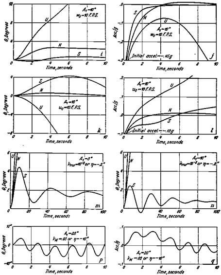
Figure 18.5 Examples of equation of motion solutions forthe Bristol F.2b (Bristol Fighter) produced in the 1930s for B. Melvill Jones’ section in Durand’s Aerodynamic Theory. The pitch attitude and normal acceleration solutions are for initial airspeed and vertical velocity perturbations and step elevator angles, at different equilibrium angles.

Aerodynamic data are generated in dimensionless form as the computed output of wind – tunnel tests and are so presented to the engineers that use equations of airplane motion. However, the special time unit т has all but disappeared from the scene. Airplane motions are calculated in terms of actual, rather than dimensionless, velocity units, except for the angles of attack and sideslip. In Glauert’s day dimensionless aerodynamic coefficients in Britain were based on pV2, not (p/2)V2. Thus, Glauert’s dimensionless stability derivatives were half as big as NACA dimensionless stability derivatives, except for the pitching moment rate derivatives mw and mq, based on the time to fly a chord, not a half-chord.

It is hard to avoid the impression that Glauert’s ingenious nondimensional form of the equations of airplane motion put the dynamic stability and control field on a side track that ultimately led nowhere. This particular contribution of the brilliant Hermann Glauert was undone by the digital computer.

Special notation for the equations of airplane motion actually started before Glauert (see Bryant and Gates, 1937). Notation for the equations of airplane motion remains an interest in Britain, the country where it all began. As part of its “Engineering Sciences Data” series, the Royal Aeronautical Society issued in 1967 a review of airplane dynamics notation and a recommended new set of standards. This work built on an impressive five-part RAE Technical Report (Hopkin, 1966). Hopkin’s point of view is

Notation is an extension of language, and a Tower of Babel should not be allowed to grow.

By the time of Hopkin’s work, the growth in applications of the equations of airplane motion had produced a great number of possible notational methods. In order to accommo­date them all without ambiguity, Hopkin was obliged to use unusual symbols, such as little half-moons over symbols. These seem not to have caught on, at least in the United States. Authors apparently are content to define symbols that are clear enough in the context of their work.

A dimensional form of the stability derivatives has become popular especially for lin­earized analysis, in which the derivatives are divided by either airplane mass or a moment of inertia function. This form provides airplane state vectors that are physically measur­able, such as velocities and angular velocities. In this system the derivative Zu stands for (dZ/дu)/m, for example. This particular form of the stability derivatives is found in the reports of the influential Systems Technology, Inc., group.

Reduced-Order Elastic Airplane Models

A complete aeroelastic airplane model incorporating states for unsteady aerody­namic effects can have well over 100 states. There are two problems with using such extended plant models in controller system design. A practical difficulty is that when control actuator, instrument, and feedback laws are added, the resultant state matrix would be too large and cumbersome for analysis. A second problem arises when some optimization methods are used to design the controller. The resultant optimal controller could require at least as many states as the plant model, an unacceptable result.

Methods have been developed that reduce the number of states to manageable levels, while at the same time preserving dominant modal characteristics over a sufficiently wide frequency band. These methods are referred to as residualization. A simple partial fraction residualization approach is described by Stevens (1992), based on work by Michael Athans. This consists of examining the plant eigenvalues and deciding which ones, usually high – frequency elastic modes, are to be dropped. A partial fraction expansion of the complete system is replaced by that of the reduced system, giving new state equations.

A more advanced residualization method is described by Newman (1994), an extension of a Stanford PhD dissertation by D. F. Enns. This is called residualization with weighted balanced coordinates.