Category Airplane Stability and Control, Second Edition

Directional Stability and Control in Ground Rolls

The modern light plane tricycle landing gear has main wheels behind the center of gravity and a steerable castering, or freely swivelling, nose wheel ahead of the center of gravity. This arrangement, invented and applied by Fred C. Weick (1936), put an end to the ground loop. The ground loop is a rapid yaw from the runway heading and a swerve off the runway. It is a problem for tail wheel landing gears, which were still used by some designers for many years after Weick’s invention.

Directional Stability and Control in Ground Rolls

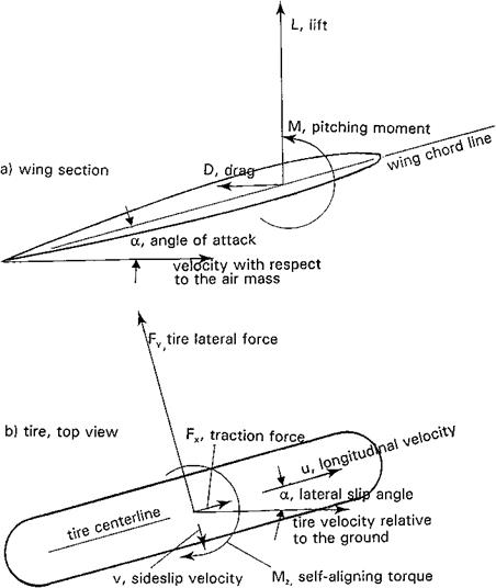
Figure 14.8 Forces and moments acting in wing sections and rolling tires. (a) Wing section. (b) Tire, top view. (From Abzug, 1999).

Directional Stability and Control in Ground Rolls

Figure 14.9 Ground roll eigenvalues for Cessna 182 at 3 airspeeds. (From Abzug, 1999)

The physical mechanism by which the main wheels of a tricycle landing gear cre­ate yaw stability during ground roll is explained in Weick’s 1936 paper. However, it is possible to model mathematically the landing rollout process in the same way we model flight dynamics (Abzug, 1999). The model produces either eigenvalues or roots for ground rollout small perturbations or nonlinear equations suitable for 6-degree-of-freedom transient analysis.

The keys to mathematical modeling of ground rolls are models for the forces and mo­ments applied to the airframe by tires in contact with the ground and for landing gear oleo struts. Both are available in the literature from automotive and aviation research. There is an interesting analogy between the forces and moments acting on wing sections and on rolling tires, as shown in Figure 14.8. Tire lateral force exhibits a linear relationship, up to a stall, with tire lateral slip angle, a sort of tire lift curve. Tire lift curve slope with slip angle is used to generate tire stability derivatives, which are added to the normal airplane small-perturbation equations of motion to produce eigenvalues in ground roll. Figure 14.9 has calculated eigenvalues for a Cessna 182 rollout at three airspeeds, as func­tions of main gear longitudinal distance from the center of gravity. Positive eigenvalues, indicating directional instability, occur for main gear locations just ahead of the center of gravity.

Linearized ground roll analysis can be applied to large airplanes with complex wheel arrangements and power-steered nose wheels, with less assurance of meaningful results. In those cases, linearized analysis may show ground handling trends, but one should plan
on full nonlinear 6-degree-of-freedom analysis, including tire forces. An extended analysis and simulation of ground roll was made for the Navy/Boeing T-45 trainer by the NASA Langley Research Center (Chambers, 2000). With proper tire dynamic models and inclusion of aircraft roll attitude, a pilot-induced yaw oscillation was reproduced.

The Penalty of Wing Sweepback on Low Subsonic Airplanes

Extra vertical tail length is obtained in canard configurations with wing-tip – mounted vertical tails by using wing sweepback. While we have learned how to provide good stall characteristics and a stable pitching moment stall break on sweptback wings,

The Penalty of Wing Sweepback on Low Subsonic Airplanes

Figure 17.1 Drawings of the tail-last Beech Super King Air B200 (above) and canard Starship 1 (below). The two airplanes are of similar size and gross weight, but the B200’s vertical tail length is 40 percent greater than the Starship’s. (From Jane’s AH the World’s Aircraft, 1987-1988)

these come at a cost in wing twist, special airfoil sections, or stall control devices such as slats, fences, and slots. Thus, wing sweepback used on a canard configuration to im­prove directional stability and control brings cost and weight penalties relative to tail-last configurations.

Aeroelastic Effects on Static Longitudinal Stability

There had been several published studies of the effects of aeroelasticity on static longitudinal stability, going back to 1942. But the subject really came to wide attention with the appearance of the very advanced, and flexible, Boeing B-47 Stratojet, first flown in 1947. Richard B. Skoog of NACA reported on the details of the stability and control static aero­elastic effects on this airplane (Skoog, 1957) based on classified work done six years earlier.

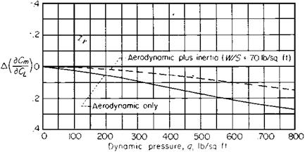
Strangely, while some individual effects are large, Skoog found that the overall aeroelastic modification to longitudinal stability and control is small (Figure 19.6). Wing symmetric bending causesthe wing tipsto wash out at increasing anglesof attack. Thismovesthe airload

Aeroelastic Effects on Static Longitudinal Stability

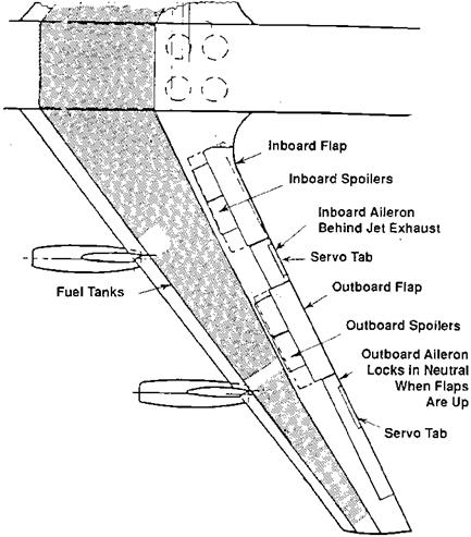
Figure 19.3 Arrangement of ailerons, spoilers, and flaps on the Boeing 707 airplane. The outboard and inboard flap-type ailerons are manually controlled, with the help of internal aerodynamic balance and balancing or geared tabs (here called servo tabs). The spoilers are of the slot-lip variety, located just ahead of the flaps. (From Cook, The Road to the 707, 1991)

relatively inboard, resulting in a forward, or destabilizing, shift of the wing aerodynamic center. However, there is a net loss in lift at positive angles of attack, a reduction in the lift curve slope. This is stabilizing, increasing the relative effect of the tail lift.

Fuselage bending under tail aerodynamic loads is destabilizing. That is, for upward tail loads, the fuselage bends upward at the rear, decreasing the tail angle of attack and the restoring moment of the tail. However, this effect is largely canceled by the downward bending of the aft fuselage under its own weight and the weight of the tail assembly, at the lower airspeeds associated with higher angles of attack. Just as wing torsion leads to aileron reversal at a sufficiently high airspeed, so does vertical bending of the aft fuselage lead to elevator or longitudinal control reversal. In the case of elevator controls, stabilizer twist adds to the problem (Collar and Grinsted, 1942).

The basic static aeroelastic analysis methods used up to the time when finite-element methods were introduced was the method of influence coefficients. Early expositions of the

Aeroelastic Effects on Static Longitudinal Stability

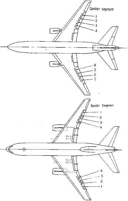
Figure 19.4 Two airplanes with slot-lip spoiler lateral controls to minimize loss in control power at high airspeeds due to wing twist: the McDonnell-Douglas DC-10 (above) and the Lockheed 1011 (below). In each case small outboard flap-type ailerons are used only at low airspeeds. (From NASA TN D 8373 and TN D 8360, 1977)

Aeroelastic Effects on Static Longitudinal Stability

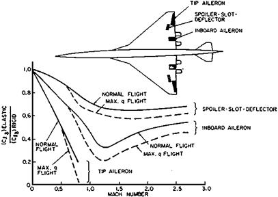
Figure 19.5 Effects ofMach number and dynamic pressure (q) on the effectiveness of three alternate aileron designs for the Boeing 2707 SST. The spoiler-slot-deflector is effective at all airspeeds, while the tip aileron reverses in effectiveness around a Mach number of 1.0. (From Perkins, Jour. of Aircraft, July-Aug. 1970)

Aeroelastic Effects on Static Longitudinal Stability

Figure 19.6 The overall effect of flexibility on static longitudinal stability ofthe Boeing B-47 airplane. The net effect is moderate, a forward neutral point shift of only 7 percent at a dynamic pressure of 500 pounds per square foot. (From Skoog, NACA Rept. 1298, 1957)

influence coefficient method were given in Pai and Sears (1949) and in a classified NACA Research Memorandum of 1950, written by Richard Skoog and Harvey H. Brown.

As early as 1954 an important relationship was stated between frequency response and static aeroelastic characteristics. If aeroelasticity were a branch of pure mathematics, this relationship would be stated as a theorem, in these terms:

Airplane frequency response at frequencies below the lowest structural bending or tor­sional modes should agree with calculated rigid-body transfer functions when quasi-static aeroelastic effects are included.

This relationship, proved experimentally with the Boeing B-47 (Cole, Brown, and Holleman, 1957), provides an important check on static aeroelastic methods. In the 1980s, this relationship provided the basis for a comparison of alternate quasi-static aeroelastic methods for the Northrop B-2 Stealth Bomber.

Empirical Approaches to Pilot-Induced Oscillations

Figure 21.1 is a time history of the pilot-induced oscillation that occurred during landing of the Space Shuttle Orbiter Enterprise in 1977. Pilot-induced oscillations (PIO), or airplane-pilot coupling (APC) incidents, in which pilot attempts at control create instability, are a natural subject for pilot-in-the-loop analysis and a major motivating factor for the method’s development. However, pilot-induced oscillations appeared long before advanced pilot-in-the-loop methods were in place. Engineers were obliged to improvise solutions empirically, so that airplane programs could proceed.

One cause of pilot-induced oscillations was apparent without much deep study If con­trol surface rate of movement is restricted for any reason, such as insufficient hydraulic

Empirical Approaches to Pilot-Induced Oscillations

Figure 21.1 Time history of pilot-induced oscillations that occurred during landing of the space shuttle Enterprise, on October 26, 1977. Time lags in the longitudinal control system are considered to have been the primary cause. (From Ashkenas, Hoh, and Teper, AIAA Paper 82-1607-CP, 1982)

fluid flow rate into actuation cylinders, the pilot is unable to reverse control motion quickly enough to stop an airplane motion, once started. A late correction drives the airplane too far in the reverse direction, requiring ever-increasing control motions. Describing func­tion analysis of rate limiting does indeed show destabilizing phase lag. Thus, one empir­ical design rule for pilot-induced oscillation avoidance is high available control surface rates.

In unpublished correspondence W. H. Phillips comments on other empirical findings on pilot-induced oscillations:

We found that very light control forces together with sensitive control were very likely to lead to pilot-induced oscillations. Viscous damping on the control stick was not the answer as this put lag in the response to control force as well as the recovery. What was needed was a large force in phase with deflection for rapid stick movements, which could be allowed to wash out quite rapidly. This could be obtained with a spring and dashpot in series. Grumman

called this a “sprashpot” and used it successfully in the feel system of the F-11F________________ The

negative Cha of flap-type controls causes the control force to fall off after the airplane responds.

An additional empirical approach to solving longitudinal pilot-induced oscillation prob­lems is the double bobweight system described in Chapter 5. An aft bobweight provides heavy stick forces to start a pitch maneuver, by applying pitching acceleration forces to the stick. Stick force falls off as the airplane responds.

Wright Controls

In the Wright brothers’ 1902 glider and their 1903 Flyer the pilot had a vertical lever for the left hand that was pulled back to increase foreplane incidence. The pilot lay on a cradle that shifted sideways on tracks to cause wing warp. To roll to the left the pilot decreased the incidence of the outer left wings and increased the incidence of the outer right wings. The rudder motion was mechanically connected to the wing warp mechanism to turn the nose left when the pilot wished to lower the left wing, and vice versa for lowering the right wing, thereby overcoming the adverse yaw due to wing warp.

When they began to fly sitting up in 1905, the Wrights retained the left-hand vertical lever for foreplane incidence but added a right-hand vertical lever for wing warp and rudder. They moved the new right-hand lever to the left for left wing down and forward for nose – left yaw. The right-hand lever was moved to the right for right wing down and aft for nose-right yaw. Turn coordination required the pilot to phase control motions, leading with yaw inputs. These unnatural control motions had to be learned and practiced on dual control machines or simple simulators. Bicyclists to the last, they never used their feet for control. They retained this scheme until 1909. Since wing warping involved considerable elastic deformation of the wing structure, they later changed the fore-and-aft motion of the right – hand lever to wing warp and mounted a new, short lever on its top for side-to-side movement to control the rudder. When the Wrights abandoned the all-moving foreplane array for an all-moving rear horizontal tail in 1911, the left-hand lever still controlled its incidence, but now reversed.

The Wrights’ patent was for mechanically linked roll and yaw controls. Other airplane builders, notably Curtiss, built airplanes with ailerons, rudders, and elevators, providing independent three-axis control. Curtiss and others asserted that the Wright machine now had independent three-axis control, but U. S. courts upheld the Wright patent against them. The courts maintained that the coupling of roll and yaw controls in the Curtiss machines existed in the mind of the aviator and was essential to the art of flying. Therefore, the Curtiss independent three-axis control infringed on the Wright patent!

Modern Light Twin Airplanes

The situation is different again in the case of the modern light twin airplanes. The first of these planes was the five-to-seven place Aero Commander 520, introduced by the Aero Design and Engineering Corporation of Culver City, California, in 1950. A year or so later Beech introduced its Model 50 Twin Bonanza, Piper its Model PA-23 Twin Stinson (later called Apache), and Cessna its Model 310 twin. These aircraft and their successors have a great deal of appeal to aviators who regularly fly on instrument flight plans into bad weather and those who want the extra safety of a second engine.

Yet by the early 1980s the safety records compiled by the modern light twins did not bear out this expectation. Writing in the AOPA Pilot of January 1983, Barry Schiff pointed out that the fatality rate following engine failure in light twins was four times that for engine failures in single-engine airplanes. It seems that relatively low-time private pilots were being trapped by the yaw and roll caused by the failure of one engine at low speeds and altitudes.

The Beech Model 95 Travelair and its higher power military derivative, the U. S. Army’s T-42A, are good examples of what could happen. After several fatal stall-spin accidents following power loss on one engine a courageous Army pilot made a series of T-42A stall tests, with symmetric and antisymmetric power. His report told of moderate wing drop in symmetric stalls, but of vicious behavior in stalls with one engine idling. The airplane would roll nearly inverted, clearly headed for a spin.

The response of the Federal Aviation Administration (FAA) to this generic light twin hazard was not to require design changes, but to warn pilots and to stress recognition and compensation for single-engine failure during training and flight tests for multiengine pilot ratings. Pilots are drilled to instantly recognize the failed engine by the mantra “Dead foot, dead engine.” Since accidents occur during the incessant single-engine drills in training, there is a special minimum airspeed for “intentionally rendering one engine inoperative in flight for pilot training.”

This is Vsse, the fourth of the special airspeeds the poor pilot has to memorize in order to legally operate multiengine airplanes. The others are Vmc or Vmca, the minimum airspeed for control with the critical engine’s propeller windmilling or feathered, the other delivering takeoff power; and Vxse and Vyse, the best angle of climb and rate of climb airspeeds with one engine inoperative. Vyse has its own marking on the airspeed dial, a blue line usually used as the landing approach airspeed under normal conditions. Evidently, if an engine fails on landing approach, one wants the airplane to be already at its best airspeed to climb away or to lose as little altitude as possible. The four special airspeeds for multiengine airplane operation are added to nine other special airspeeds (six if the airplane has no wing flaps or retractable landing gear) to be remembered.

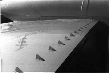
In spite of the FAA’s apparent disinterest in obliging light twin builders to design safe single-engine behavior into their airplanes, there have been some attempts made in this direction. There is an FAA-approved design retrofit of vortex generators for the upper wing surfaces of some light twins. The installation reduces Vmca, the minimum airspeed for control with an engine out (Figure 4.3). Vortex generators are tiny (about 2 inches square)

Modern Light Twin Airplanes

Figure 4.3 Vortex generators fitted to the upper wing surface of a Piper PA-31-3 50 Chieftan light twin-engine airplane, to reduce minimum single-engine control speed Vmca. This installation of 43 generators on each wing was designed by Boundary Layer Research, Inc., of Everett, WA.

low-aspect ratio wings that stick out of a surface. The tip vortices from a spanwise row of generators set at angles of attack energize the surface’s boundary layer by mixing in with it high-energy air from the surrounding flow. The energized boundary layer tends to remain attached, avoiding separation or stall.

According to John G. Lee (1984), vortex generators were invented by “an introspective and rather unapproachable loner” named Hendrik Bruynes, who used eight vortex generators to correct separation from the walls of the diffuser in a new 18-foot United Aircraft Research Department wind tunnel. While Bruynes was named in the vortex generator patent, Lee credits Henry H. Hoadley with the key idea of reversing the angles of alternate generators. The Forty-Second Annual Report of the NACA, dated 1956, flatly credits H. D. Taylor of United Aircraft as the developer of vortex generators; no mention is made of either Bruynes or Hoadley.

Stability and Control at the Design Stage

In the preliminary layout of a new airplane, the stability and control engineer is generally guided by some well-known principles related to balance and tail sizing, for example. Once a preliminary design is laid out, its main stability and control characteristics can be predicted entirely from drawings. This includes the neutral point (center of gravity for zero-static longitudinal stability), static directional (weathercock) and lateral (dihedral effect) stability, and assurance that the airplane can be trimmed to zero-pitching moment over its lift coefficient and center of gravity ranges.

In the best of circumstances, the new design has a family resemblance to an earlier design. Then the estimations resemble extrapolations from known, measured characteristics. All airplane manufacturers seem to maintain proprietary aerodynamic handbook collections and correlations of stability and control data from previous designs. This is a great help if the extrapolation route is indicated. Aside from these private collections, there is a large body of theory and correlations from generalized wind-tunnel data that can be called upon for prediction or estimation.

A closely related subject to the prediction of stability and control characteristics entirely from drawings is the problem posed at the next stage in an airplane’s development, when wind-tunnel test data have been obtained. In former times, one was often asked to prepare a complete set of predicted flying qualities using the wind-tunnel data and any flight control details that may have been available at the time. Instead, current practice is to plug wind- tunnel test and control system data into a flight simulator, for pilot flying qualities evaluation. Radio-controlled flying scale models are an alternate stability and control source for projects that cannot afford wind-tunnel tests.

The three design-stage topics – layout principles, estimation from drawings, and estima­tion from wind-tunnel data – are treated in this chapter.

The Role of Rotary Derivatives in Spins

The rotary derivatives are the force and moment coefficient derivatives with respect to dimensionless angular velocity The rotary derivatives appear in the airplane equations of motion for normal unstalled flight, as well as for spinning flight. However, at the relatively low airspeeds and high angular velocities for spinning flight, the rotary derivatives are much more important than they are for unstalled flight. Physically, under spinning conditions there will be large differences in local flow angles of attack at different parts of the airplane, and possibly local separated flows.

Stated otherwise, the rotary derivatives are generally of secondary importance to flight simulation and flight control design for normal unstalled flight. If the airplane has stability augmentation systems that drive the control surfaces to provide artificial damping, this is even more true; artificial damping swamps out the rotary derivatives that supply natural aerodynamic damping. Thus it is that, at least in modern times, the drive to refine analytic and measurement techniques for the rotary derivatives has come from spinning studies.

The early 1950s saw a rush of 5- and 6-degree-of-freedom inertial coupling computer simulations, as told in Chapter 8, “The Discovery of Inertial Coupling.” It is interesting that some of the same investigators, such as Cecil V Carter, John H. Wykes, and Leo Celniker, who helped crack inertial coupling with their simulations moved on to spin simulation using analog or digital computers. The motivation was there, because the same airplane loading characteristics that lead to inertial coupling also lead to post-stall gyrations and departures, motions not easily studied in free-spinning wind tunnels.

The problem was that this period coincided with a shutdown of rotary balance testing at NACA. The NACA rotary balance was updated in the late 1950s, but it was not used for analytical studies until several years had passed. Thus, the spin computer analysis results reported at the 1957 Wright Air Development Center Airplane Spin Symposium (Westbrook and Doetsch, 1957), made without the benefit of current rotary balance data, came under criticism for using inadequate rotary derivatives by knowledgeable people such as Dr. Irving C. Statler and Ronald F. Sohn.

Supersonic Directional Instability

A rather simple static directional instability problem first appeared in a test flight of the North American F-100 Super Sabre. It is simple because the problem has one well-known cause, the loss in lifting surface effectiveness as Mach number increases be­yond 1. The instability of bodies of revolution, on the other hand, remains essentially invariant with Mach number. Static directional stability is to a first order the balance be­tween the unstable fuselage and the stabilizing vertical tail. The vertical tail is supposed to

Supersonic Directional Instability

Figure 11.15 A North American XB-70 airplane in flight. The wing tips are deflected downward for increased directional stability at supersonic speeds. (From Bilstein, Orders of Magnitude, 1989)

dominate, but as its effectiveness, or lift curve slope, drops off neutral stability is eventually reached.

The point of neutral directional stability on any supersonic airplane evidently should be beyond the attainable flight envelope. However, supersonic directional instability actually occurred in a dive on an early F-100 before an enlarged vertical tail was adopted, leading to a tragic accident. On the F-100 vertical tail, bending contributed to the loss in effectiveness. Modern stability augmentation techniques can provide artificial directional stability at su­personic speeds, if it is impractical or economically undesirable to have a large enough vertical tail.

The North American XB-70 bomber used a configuration change to return directional stability to acceptable levels at high supersonic Mach numbers. The wing outer panels folded down 65 degrees for flight at a Mach number of 2 and a larger angle above (Figure 11.15). Unfortunately, this made the dihedral effect negative, resulting in poor flying qualities. This was corrected on the second XB-70 prototype by a triangular wedge welded between the fuselage and wing, producing 5 degrees of geometric dihedral.

There was concern that if the XB-70’s wing tips ever stuck down in the folded position, the airplane could not be landed because of lack of ground clearance. Fortunately, this never happened. An additional benefit of the folded-down wing tips was reduction in excess static longitudinal stability at supersonic speeds, due to the change in planform. Also, compression lift was generated at supersonic speeds by shock waves from the folded tips producing positive pressures on the bottom of the wing and fuselage.

The British Aircraft Corporation’s TSR-2, designed for a Mach number of 2.0, had neutral directional stability at a Mach number of 1.7. The vertical fin was made small to

reduce tail loads in high-speed flight at low altitudes. The airplane was canceled for other reasons before a directional stability augmenter could be installed for flight faster than a Mach number of 1.7.

Early Safe Personal Airplane Designs

Aeromarine-Klemm As imported from Germany, it had unsafe spin character­istics. The wing was modified to have less taper and thicker tip sections. Control movement was restricted, and the center of gravity range was moved forward. All of these modifications, apparently arrived at empirically, were in a direc­tion to improve spin resistance, and this airplane became one of the very first to be called incapable of spinning. Actually, a spin could be forced, but the airplane had to be held into the spin; and with free controls it would recover. Aeromarine-Klemm models were produced with several different engines from the late 1920s to 1932.

Stout Sky Car Designed in 1931, the Sky Car was one of the first two-control airplanes. It had floating wing tip ailerons that were weight overbalanced, mak­ing them float symmetrically with slight negative lift. When deflected for a roll, proverse yaw, or yaw in the direction of the roll, resulted. No rudder control was needed to coordinate the roll. The Sky Car had a tricycle landing gear and limited up-elevator travel. It was a stubby, odd-looking machine, a biplane with a small vertical tail.

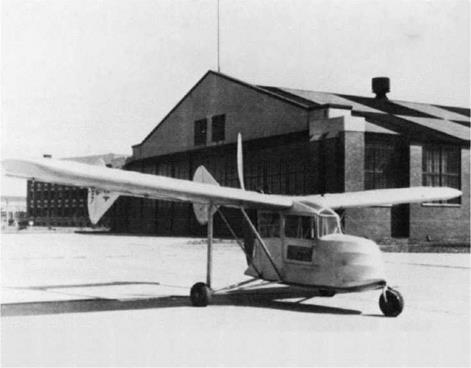
Weick W-1A In 1935 and 1936, this airplane was a test bed for several safety innovations. It had full-span flaps that could be deflected to 80 degrees to make steep descents into small fields. Slot lip spoilers provided lateral control (Figure 15.2). The not-yet-famous Robert T Jones studied two-control oper­ation and told Weick that the W-1A’s spoiler ailerons would be ideal for the purpose, as they turned out to be. As in the Stout Sky Car, elevator control was limited to prevent stall.

Stearman-Hammond Model Y and the Gwinn Aircar Both of these airplanes were designed with features of the Weick W-1A. The Model Y won a safe airplane competition sponsored by the Department of Commerce. The Aircar had no rudder at all. Its interior looked like an Oldsmobile, with Oldsmobile steering wheel and instruments.

ERCO Model 310 and the Ercoupe Fred Weick’s Ercoupe was the only one of the early safe airplanes to make it into production, which started in 1940 (Figure 15.3). The Ercoupe has the two-control, restricted elevator control and tricycle landing gear features ofthe W-1 A. The U. S. Civil Aeronautics Authority certified the Ercoupe as “characteristically incapable of spinning” and cut the dual time required to solo from 8 to 5 hours and the time for private pilot cer­tification from 35 to 25 hours.

With the yoke hard back, rapid full aileron control deflections from side to side produce nothing more exciting than falling-leaf motions. Cross-wind touchdowns are made with the airplane headed into the relative wind. When the pilot releases the controls the Ercoupe straightens out for its ground roll.

Early Safe Personal Airplane Designs

Figure 15.2 The 1935 Weick W-1A airplane, photographed in front of an NACA Langley Field hangar. This innovative airplane had full-span flaps and spoiler ailerons, limited up-elevator travel, and two-control operation. (From Weick, From the Ground Up, 1988)