Category Airplane Stability and Control, Second Edition

Irreversible Powered Controls

An irreversible power actuator for aerodynamic control surfaces is in principle much simpler than hydraulic control boost. There is no force balancing linkage between the pilot and the hydraulic cylinder to be designed. Irreversible powered controls are classic closed loops in which force or torque is applied until a feedback signal cancels the input signal. They are called irreversible because aerodynamic hinge moments have no effect on their positions.

An easily comprehended irreversible power control unit is that in which the control valve body ishard-mounted to the actuation or power cylinder. Pilot control movement or electrical signals move the control valve stem off center, opening ports to the high pressure, or supply hydraulic fluid and low pressure, or sump hydraulic fluid. Piping delivers high-pressure fluid to one side of the piston and low-pressure fluid to the other. The piston rod is anchored to structure and the power cylinder to the control surface. When the power cylinder moves with respect to structure in response to the unbalanced pressure it carries the control valve

body along with it. This centers the control valve around the displaced stem, stopping the motion. The airplane’s control surface has been carried to a new position, following up the input to the control valve in a closed-loop manner.

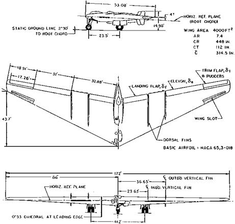
The first irreversible power controls are believed to have been used on the Northrop XB-35 and YB-49 flying wing airplanes. Irreversibility was essential for these airplanes because of the large up-floating elevon hinge moment at high angles of attack, as the stall was approached. This was unstable in the sense that pilot aft-yoke motion to increase the angle of attack would suddenly be augmented by the elevon’s own up-deflection. One of the N9M flying scale models of the Northrop flying wings was lost due to elevon up-float (Sears, 1987). The YB-49’s irreversible actuators held the elevons in the precise position called for by pilot yoke position, eliminating up-float. Other early applications of irreversible power controls were to the de Havilland Comet; the English Electric Lightning P1.A, which first flew in 1954; and the AVRO Canada CF-105 Arrow, which first flew in 1958.

Howard (2000) believes that the Comet application of irreversible powered controls was the first to a passenger jet. The U. K. Air Registration Board “made the key decision to accept that a hydraulic piston could not jam in its cylinder, a vital factor necessary to ensure the failure-survivability of parallel multiple-power control connections to single surfaces.”

While irreversible power controls are simple in principle, it was several years before they could be used routinely on airplanes. The high powers and bandwidths associated with irreversible power controls, as compared with earlier boosted controls, led to system limit cycling and instabilities involving support structures and oil compressibility. These problems were encountered and solved in an ad hoc manner by mechanical controls engineer T. A. Feeney for the Northrop flying wings on a ground mockup of the airframe and its control system, called an iron bird. An adequate theory was needed for power control limit cycle instability, to explain the roots of the problem. This was presented by D. T McRuer at a symposium in 1949 and subsequently published (Bureau of Aeronautics, 1953).

The post-World War II history of gradual improvements in the design of irreversible power controls is traced by Robert H. Maskrey and W. J. Thayer (1978). They found that Tinsley in England patented the first two-stage electromechanical valve in 1946. Shortly afterwards, R. E. Bayer, B. A. Johnson, and L. Schmid improved on the Tinsley design with direct mechanical feedback from the second-stage valve output back to the first stage.

Engineers at the MIT Dynamic Analysis and Controls Laboratory added two improve­ments to the two-stage valve. The first was the use in the first stage of a true torque motor instead of a solenoid. The second improvement was electrical feedback of the second-stage valve position. In 1950, W. C. Moog, Jr., developed the first two-stage servovalve using a frictionless first-stage actuator, a flapper or vane. Valve bandwidths of up to 100 cycles per second could be attained. The next significant advance was mechanical force feedback in a two-stage servovalve, pioneered by T. H. Carson, in 1953. The main trends after that were toward redundancy and integration with electrical commands from both the pilot and stability augmentation computers.

In general, satisfactory irreversible power control designs require attention to many details, as described by Glenn (1963). In addition to the limit cycling referred to previously, these include minimum increment of control, position and time lags, surface positioning accuracy, flexibility, springback, hysteresis, and irreversibility in the face of external forces.

Spinning and Recovery

Spins are uncontrolled rotations of a fully stalled airplane. In aviation’s early years, when spins were first encountered, spinning airplanes descended more or less straight down. The motion was mainly yawing and quite stable. Stability and control engineers were concerned only with recovery from spins into unstalled flight.

The coming of jet airplanes saw mass distribution changes that caused spins to be oscillatory. Emphasis shifted somewhat to the entry phase of spins and design features that made spin entry less likely during flight operations. This chapter traces the changing nature of airplane spinning from the early days and the corresponding engineering responses.

9.1 Spinning Before 1916

The spinning experience in the early days of aviation is described by B. Melvill Jones (1943):

In the early days of flying – before 1916 – the spin generally ended fatally, because what later proved to be the most effective means of checking it was in some respects contrary to the natural reaction of the pilot to the realization that he was diving towards the earth. About 1916 it was discovered that an effective way of checking the type of spin which was common in those days was to thrust the control stick forward and apply rudder in the sense opposed to the rotation. For some time after this knowledge had become general, relatively few fatalities due to spinning occurred, provided that there was enough air-room for the spin to be checked and the resulting steep dive converted into horizontal flight; the spin then became an ordinary manoeuvre.

Jones goes on to tell of the first flat spins, which occurred around 1919. Previously, spins had been steep in pitch attitude, with corresponding low stalled angles of attack of 25 to 35 degrees. On the other hand, the new flat spins had low pitch attitudes and high angles of attack, 45 degrees or higher, and high rotation rates. The flat spins were more dangerous than the early variety. An interesting speculation is that the invention of the parachute increased the number of survivors who could give reports of spins that had become uncontrollable, thus accounting for a seeming increase in the number of flat spins.

Transonic Aerodynamic Testing

Aerodynamics engineers, including stability and control designers, were baffled in their attempts to get reliable wind-tunnel measurements at transonic speeds, near a Mach number of 1.0. High-speed wind tunnels suffered from the choking phenomenon, in which normal shocks originating on models under test spread across the test section as speed was increased, preventing further increases.

W. Hewitt Phillips credits Robert R. Gilruth with the invention of one method to circum­vent this problem, the wing flow method. Figure 11.6 shows how small wing or complete configuation models are mounted normal to the wing upper surface of an airplane, in a

Transonic Aerodynamic Testing

Figure 11.6 A sweptback-wing half-model mounted on the upper wing surface of a North American P-51, for wing flow testing during dives. The model is transonic, while the airplane is not. (From Phillips, Jour, off theAmer. Avia. Histor. Soc., 1992)

region where the local Mach number is much higher than the airplane’s flight speed. Phillips describes the method as follows:

A special glove is built on the wing to give a more uniform flow region. As the airplane [P-51 Mustang] goes through its dive and pullout, the model is oscillated back and forth at a frequency of about one cycle per second, to vary either the angle of attack or flap deflection. The forces on the model are continuously recorded with a strain gage balance and a recording oscillograph. The dive lasts about 30 seconds and in this period the Mach number at the model increases from about 0.7 to 1.2… .A vacuum-operated windshield wiper motor was usually used to oscillate the model (Phillips, 1992).

The wing flow method and data from small drop models were both effectively obso- leted with the invention of the porous or slotted-throat transonic wind tunnel by Ray H. Wright, of the NACA Langley laboratory, around 1948. The slotted-throat wind tunnel allows measurements to be made through a Mach number of 1.0.

14.8.2 Knob Twisting

Informal and rather elementary stability and control derivative extraction took place starting in the early 1950s, when the first electronic analog computers, such as the Reeves Instrument Company’s REAC, were used to get time histories of airplane motions. Numerical values of individual dimensionless stability derivatives, such as C„e, are represented by potentiomenter settings on analog computers. Computed airplane motions appear on pen-type recorder records. The experimenter can try to match an actual flight record for a given control input by resetting potentiometers and rerunning cases over and

over. Since potentiometer settings are controlled by knobs on the face of the analog computer cabinet, this trial-and-error process is known familiarly as knob twisting.

Knob twisting is not altogether a random process, since an experimenter is guided by approximations to the modes of airplane motion. We know, for example, that the period of the Dutch roll oscillation is controlled by the directional stiffness derivative Cn. The amplitude of the roll oscillation relative to that of sideslip or yawing velocity is controlled by the dihedral effect derivative Clp, and so on.

Modern Canard Tactical Airplanes

The canard disadvantages enumerated above either do not apply or are over­whelmed by other considerations in the case of tactical airplanes designed for superma­neuverability, or for controllable flight beyond the stall. The stability and control of tactical airplanes in the supermaneuverability regime are covered in Chapter 10, “Tactical Airplane Maneuverability.”

Control of the vortex system shed from the fighter nose is known to be critical for controllable flight beyond the stall. Forebody strakes have been found valuable for this purpose. Canards offer another means for shaping the forebody vortex system. They are used in some modern fighter designs, such as the Sukhoi Su-35, the Saab JAS 39 Gripen (Figure 17.3), the IAI Lavi, the Rockwell/MBB X-31A Enhanced Fighter Maneuverability (EFM), and the Eurofighter 2000.

CHAPTER 18

Mean and Structural Axes

Even after the advent of panel methods, there remain controversial aspects of the quasi-static aeroelastic problem, related to the choice of axes. Structural distortions must be referred to some set of reference axes. There are essentially two sets of reference axes that will serve. One choice, called structural axes, corresponds to a natural reference for laboratory structural deflection tests or their analytical equivalent. Structural axes are aligned with a central hard section of the airplane, such as the wing interspar structure at the airplane’s centerline.

The second choice, which is the only one that is consistent with the ordinary pitch – plunge equations of airplane motion, are mean axes. Mean axes are a familiar concept in normal mode analysis. They correspond to the midpoint of normal mode oscillations, the point at which all transverse deflections are momentarily zero. While structural influence coefficients may well be measured or calculated in an arbitrarily chosen structural axis system, pitch and plunge motions of the aeroelastic airplane must be calculated in mean axes, to avoid systematic error (Milne, 1964, 1968). A refinement of mean axes is the use of principal axes in which distributed moments of inertia are accounted for in addition to longitudinal mass distributions.

John H. Wykes and R. E. Lawrence used both mean and structural axes in a 1965 study of aerothermoelastic effects on stability and control, but they noted the difficulties involved in relating airplane angle of attack in the two systems. The angle of attack difficulty found by Wykes and Lawrence is resolved in an offline transformation of the results, such as pitch attitude and angle of attack time histories, from mean to structural axes (Rodden and Love, 1984). The transformation is feasible at the end of the dynamics calculations. The Rodden and Love paper, corrected in Dykman and Rodden (2000), also presents transformation equations from mean to structural axes.

The Rodden papers have an interesting proof of the fallacy of using the more convenient structural axes for dynamics studies in place of mean axes, as has been done by investigators unwilling to face angle of attack difficulties. In a simple swept-forward airplane example using structural axes, load factor and pitching acceleration time histories depend on the fixity choice of the axes, an evidently incorrect result. This error is avoided with mean axes. Mean axes are used in the FLEXSTAB program.

The Crossover Model and Pilot-Induced Oscillations

The crossover model has proved to be of great value in understanding pilot-induced oscillations. The way has been opened for validating empirical corrections for the phe­nomenon, such as described by Phillips, and for the development of new concepts in the area and superior flying qualities designs.

Duane McRuer provides a comprehensive survey of pilot-induced oscillations in a report for the Dryden Flight Research Center (McRuer, 1994). Having been experienced by the Wright brothers, pilot-induced oscillations qualify as the senior flying qualities problem. Recent dramatic flight experiences, combined with the availability of advanced analysis methods, have given the subject fresh interest. Between the years 1947 and 1994, there were over 30 very severe reported cases, in airplanes ranging from a NASA paraglider to the space shuttle Orbiter. McRuer proposes three pilot-induced oscillation categories, as follows:

essentially linear;

quasi-linear, with surface rate or position limiting;

essentially nonlinear, including pilot or mode transitions.

The Crossover Model and Pilot-Induced Oscillations

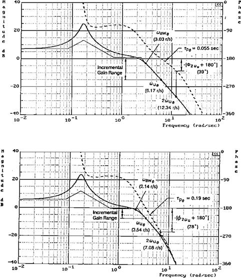
Figure 21.4 Pilot-airplane open-loop frequency responses for two configurations of the USAF/ Calspan variable-stability T-33. The upper case, with no pilot-induced oscillations, has the ideal integrator shape in the vicinity of crossover. The lower case, with severe pilot-induced oscillations, has a steeper slope and more phase lag at high frequencies. (From McRuer, STI Technical Rept. 2494-1, 1994)

An important validation of the crossover model approach to the first category was furnished by analysis of fully developed pilot-induced oscillations on the USAF/Calspan variable-stability NT-33 (Bjorkman, 1986). In six severe cases there were large effective open-loop system delays, departing from the ideal integrator-type airframe transfer func­tion in the region of crossover (Figure 21.4). The required pilot dynamics for compensatory operation thus required

a great deal of pilot lead as well as exquisitely precise adjustment of pilot equalization and gain to approximate the crossover law and to close the loop in a stable manner.

Linear pilot-induced oscillations include complex interactions with airplane flexible modes. Mode-coupled oscillations have been experienced on the F-111, the YF-12, and the Rutan Voyager. Control surface rate-limiting pilot-induced oscillations were discussed previously.

Essentially nonlinear pilot-induced oscillations have arisen chiefly in connection with pilot and mode transitions. In one such case, weight-on-wheel and tail strike switches changed the stability augmentation control laws on the Vought/NASA fly-by-wire F-8, presenting the pilot with a rapid succession of different dynamics (McRuer, 1994). The pilot was unable to adapt in time. Mode transitions, either as a function of pilot input amplitude or automatic mode changes, are a particular source of pilot-induced oscillations in modern fly-by-wire flight control systems. The importance of avoiding pilot-induced oscillations on fly-by-wire transport airplanes led to the study discussed in Sec. 11.

G. H. Bryan and the Equations of Motion

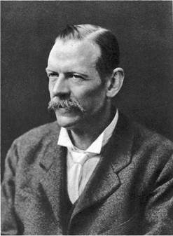
The mathematical theory of the motion of an airplane in flight, considered as a rigid body with 6 degrees of freedom, was put into essentially its present form by Professor George Hartley Bryan (frontispiece) in England in 1911. In an earlier (1903) collaboration with W. E. Williams, Bryan had developed the longitudinal equations of airplane motion only. Bryan’s important contribution rested on fundamental theories of Sir Isaac Newton (1642-1727) and Leonhard Euler (1707-1783). Today’s stability and control engineers are generally

Figure 1.7 The perturbation form of Bryan’s equations of airplane motion. The longitudinal equations are above, the lateral equations below. Note the absence of control derivatives. (From Bryan, Stability in Aviation, 1911)

astonished when they first see these equations (Bryan, 1911). As his book’s (Bryan, 1911) title indicated, he focused on airplane stability, not control. Aside from minor notational differences, Bryan’s equations are identical to those used in analysis and simulation for the most advanced of today’s aircraft (Figures 1.6 and 1.7).

Not surprisingly, at this early date he does not cover in detail control force and moments, nor does he treat the airplane as an object of control. The perturbation equations in Fig. 1.7 include stability but not control derivatives. The influence of external disturbances such as gusts is also not addressed, although he recognizes this and other problems by presenting a summary of questions not covered in his book that set an agenda for years of research.

Bryan calculated stability derivatives based on the assumption that the force on an airfoil is perpendicular to the airfoil chord. W. Hewitt Phillips points out that while this theory is not the most accurate for subsonic aircraft, it is quite accurate for supersonic aircraft, particularly those with nearly unswept wings, such as the Lockheed F-104. Thus, Bryan might be considered even more ahead of his time than is usually acknowledged.

Bryan obtained solutions for his equations and arrived at correct modes of airplane longitudinal and lateral motion. At the end of Stability in Aviation, Bryan reviews earlier stability and control theories by Captain Ferber, Professor Marcel Brillouin, and MM. Soreau and Lecornu of France; Dr. Hans Reissner of Germany; and Lieutenant Luigi Crocco of Italy.

Little progress was made at first in the application of Bryan’s equations because of the difficultiesof performing the calculationsand the uncertaintiesin estimating the airloadscor – responding to airplane motions. The airloads associated with rolling, pitching, and yawing motions, the so-called rotary loads, were a particular problem. Early efforts were made at the National Physical Laboratory in England to measure these rotary airloads in a wind tunnel.

The evolution of Bryan’s equations of airplane motion into an indispensable tool for stability and control researchers and designers is traced in Chapter 18 of this book.

Special VTOL Jet Inflow Effects

Deflected jet VTOL airplanes such as the Hawker-Siddeley Harrier and the McDonnell Douglas AV-8B Harrier II can have troublesome jet inflow effects on static

Special VTOL Jet Inflow Effects

Figure 4.7 The low tail position that produces good stability at high lift coefficients for swept-wing airplanes can destabilize the airplane as a deflected jet VTOL. The left-hand diagram shows stability with jet power off; the right-hand diagram shows instability for a jet deflection angle of 60 degrees. (Reprinted with permission from SAE Paper No. 864A, © 1964, Society of Automotive Engineers, Inc.)

longitudinal stability. Problems can arise at jet deflection angles that are intermediate between hovering and normal flight.

As shown in Figure 4.7, jet deflection angles of about 60 degrees can put the horizontal tail in an effective high position relative to the jet flow field. This causes large downwash angles over the tail (McKinney, Kuhn, and Reeder, 1964). This occurs in spite of an actual low tail position relative to the wing chord plane, which is necessary on swept wings to avoid transonic pitchup. In other words, finding a single horizontal tail vertical position to give good static longitudinal stability under all flight conditions may be difficult for swept-wing deflected-jet VTOL airplanes of the Harrier type.

An additional inflow problem occurs with tilt-rotor VTOL airplanes at high descent rates at low airspeeds. This problem is shared with rotary-wing aircraft. High descent rates can lead to asymmetric loss in lift and uncontrollable roll, because of upflow through propeller disks due to the descent rate. The upflow interferes with the downflow required for lift.

Downwash and Sidewash

The flow behind wing-body combinations is deflected from the free-stream values, affecting the stabilizing contributions of the tail surfaces. Downwash is the downward deflection of the free stream behind a lifting surface, a momentum change consistent with the lift itself. Sidewash is a sideward deflection of the free stream, related to the side force on the wing-fuselage combination in side-slipping flow. Sidewash at the vertical tail is dominated by vortices that accompany the downwash when sideslip distorts the pattern.

Wing downwash charts for the symmetric flow (no sidewash) case suitable for preliminary design became available in 1939 from Silverstein and Katzoff. Later investigators broadened the design charts to include the effects of landing flap deflection, ground plane interference, wing sweep, and compressibility.

An interesting sidewash effect is the loss in directional stability experienced by receiver aircraft in close trail to tanker aircraft. Following reports of directional wandering of receiver aircraft, Bloy and Lea (1995) tested tanker-receiver model combinations in a low-speed wind tunnel. These results, together with vortex lattice modeling, confirm the loss in receiver directional stability. Rolled-up tanker wing tip vortices acting on the receiver vertical tail in a low position cause the problem.