Category Airplane Stability and Control, Second Edition

Very Large Aircraft

It is not at all certain that the supersonic Concorde will be followed by fleets of new supersonic cruise civil transports. However, the prospect of subsonic commercial jet transports larger and heavier than the Boeing 747-400 is almost a certainty, with some Airbus A380 superjumbo jets already on order. Thus, it is reasonable to review the expected stability and control problems for very large airplanes.

23.1 The Effect of Higher Wing Loadings

Higher wing loadings than on airplanes of the Boeing 747-400 and advanced 777 classes seem inevitable for commercial airplanes of the 1,000-seat category, if these air­planes are to fit into current airport terminals, runways, taxiways, and maintenance facilities that have had reasonable modifications. Folding wings, tandem main wings, or some other radical departures from current technology would get around the necessity of higher wing loadings, but radical innovations are unlikely in airplanes that will be as expensive as super­jumbo jets. All-wing superjumbo jets have been studied by several groups, but the Boeing and Airbus designs for superjumbo jets show quite conventional arrangements.

Some of the stability and control consequences of using high wing loadings in very large airplanes can be predicted. Higher wing loadings than current practice imply higher fuel weights relative to the aerodynamic forces generated by the wings and stabilizing surfaces. Dynamic fuel slosh effects, a nonproblem for 747-class airplanes, will require a fresh analytical look.

G. H. Bryan and the Equations of Motion

The mathematical theory of the motion of an airplane in flight, considered as a rigid body with 6 degrees of freedom, was put into essentially its present form by Professor George Hartley Bryan (frontispiece) in England in 1911. In an earlier (1903) collaboration with W. E. Williams, Bryan had developed the longitudinal equations of airplane motion only. Bryan’s important contribution rested on fundamental theories of Sir Isaac Newton (1642-1727) and Leonhard Euler (1707-1783). Today’s stability and control engineers are generally

Figure 1.7 The perturbation form of Bryan’s equations of airplane motion. The longitudinal equations are above, the lateral equations below. Note the absence of control derivatives. (From Bryan, Stability in Aviation, 1911)

astonished when they first see these equations (Bryan, 1911). As his book’s (Bryan, 1911) title indicated, he focused on airplane stability, not control. Aside from minor notational differences, Bryan’s equations are identical to those used in analysis and simulation for the most advanced of today’s aircraft (Figures 1.6 and 1.7).

Not surprisingly, at this early date he does not cover in detail control force and moments, nor does he treat the airplane as an object of control. The perturbation equations in Fig. 1.7 include stability but not control derivatives. The influence of external disturbances such as gusts is also not addressed, although he recognizes this and other problems by presenting a summary of questions not covered in his book that set an agenda for years of research.

Bryan calculated stability derivatives based on the assumption that the force on an airfoil is perpendicular to the airfoil chord. W. Hewitt Phillips points out that while this theory is not the most accurate for subsonic aircraft, it is quite accurate for supersonic aircraft, particularly those with nearly unswept wings, such as the Lockheed F-104. Thus, Bryan might be considered even more ahead of his time than is usually acknowledged.

Bryan obtained solutions for his equations and arrived at correct modes of airplane longitudinal and lateral motion. At the end of Stability in Aviation, Bryan reviews earlier stability and control theories by Captain Ferber, Professor Marcel Brillouin, and MM. Soreau and Lecornu of France; Dr. Hans Reissner of Germany; and Lieutenant Luigi Crocco of Italy.

Little progress was made at first in the application of Bryan’s equations because of the difficultiesof performing the calculationsand the uncertaintiesin estimating the airloadscor – responding to airplane motions. The airloads associated with rolling, pitching, and yawing motions, the so-called rotary loads, were a particular problem. Early efforts were made at the National Physical Laboratory in England to measure these rotary airloads in a wind tunnel.

The evolution of Bryan’s equations of airplane motion into an indispensable tool for stability and control researchers and designers is traced in Chapter 18 of this book.

Special VTOL Jet Inflow Effects

Deflected jet VTOL airplanes such as the Hawker-Siddeley Harrier and the McDonnell Douglas AV-8B Harrier II can have troublesome jet inflow effects on static

Special VTOL Jet Inflow Effects

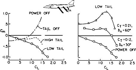
Figure 4.7 The low tail position that produces good stability at high lift coefficients for swept-wing airplanes can destabilize the airplane as a deflected jet VTOL. The left-hand diagram shows stability with jet power off; the right-hand diagram shows instability for a jet deflection angle of 60 degrees. (Reprinted with permission from SAE Paper No. 864A, © 1964, Society of Automotive Engineers, Inc.)

longitudinal stability. Problems can arise at jet deflection angles that are intermediate between hovering and normal flight.

As shown in Figure 4.7, jet deflection angles of about 60 degrees can put the horizontal tail in an effective high position relative to the jet flow field. This causes large downwash angles over the tail (McKinney, Kuhn, and Reeder, 1964). This occurs in spite of an actual low tail position relative to the wing chord plane, which is necessary on swept wings to avoid transonic pitchup. In other words, finding a single horizontal tail vertical position to give good static longitudinal stability under all flight conditions may be difficult for swept-wing deflected-jet VTOL airplanes of the Harrier type.

An additional inflow problem occurs with tilt-rotor VTOL airplanes at high descent rates at low airspeeds. This problem is shared with rotary-wing aircraft. High descent rates can lead to asymmetric loss in lift and uncontrollable roll, because of upflow through propeller disks due to the descent rate. The upflow interferes with the downflow required for lift.

Downwash and Sidewash

The flow behind wing-body combinations is deflected from the free-stream values, affecting the stabilizing contributions of the tail surfaces. Downwash is the downward deflection of the free stream behind a lifting surface, a momentum change consistent with the lift itself. Sidewash is a sideward deflection of the free stream, related to the side force on the wing-fuselage combination in side-slipping flow. Sidewash at the vertical tail is dominated by vortices that accompany the downwash when sideslip distorts the pattern.

Wing downwash charts for the symmetric flow (no sidewash) case suitable for preliminary design became available in 1939 from Silverstein and Katzoff. Later investigators broadened the design charts to include the effects of landing flap deflection, ground plane interference, wing sweep, and compressibility.

An interesting sidewash effect is the loss in directional stability experienced by receiver aircraft in close trail to tanker aircraft. Following reports of directional wandering of receiver aircraft, Bloy and Lea (1995) tested tanker-receiver model combinations in a low-speed wind tunnel. These results, together with vortex lattice modeling, confirm the loss in receiver directional stability. Rolled-up tanker wing tip vortices acting on the receiver vertical tail in a low position cause the problem.

The Break with the Past

The 1947 NACA tail design requirements for satisfactory spin recovery stood relatively unchallenged until a series of NASA spin tunnel tests and some experiments at the Cessna Company in the late 1970s. Motivated somewhat by the Grumman/American AA-1B Yankee experience, NASA started a broad-based review of light airplane spin re­covery. W. H. Phillips credits Joseph R. Chambers with initiating this work. The centerpiece of the program was a flight test fleet of four airplanes: a Cessna 172 Skyhawk, a modified Beech C23 Sundowner, a nonproduction Piper PA-28R T-tail Arrow, and a modified Yankee. Initial results from the review represent a distinct break with past NACA work, in particular, the 1947 TDPF tail design criterion. Nine tail configurations were tested on a model of the Yankee in the 20-foot Langley Spin Tunnel. Six of the nine designs were predicted to have satisfactory spin recovery characteristics according the 1947 TDPF criterion, yet only four showed satisfactory recovery in the spin tunnel (Burk, Bowman, and White, 1977). The investigators concluded:

On the basis of the results of the present investigation, the tail design criterion for light airplanes, which uses the tail damping factor (TDPF) as a parameter, cannot be used to predict spin recovery characteristics.

According to Burk, Bowman, and White, TDPF was intended to serve only as a conser­vative guideline for tail design, not as a criterion. Having made this decisive break with 30 years of stability and control design practice, the statement is softened somewhat in words that followed those quoted above, as follows:

However, certain principles implicit in the criterion are still valid and should be considered when designing a tail configuration for spin recovery. It is important to provide as much damping to the spin as possible (area under the horizontal tail), and it is especially important to provide as much exposed rudder area at spinning attitudes (unshielded rudder volume coefficient (URVC)) in order to provide a large antispin moment for recovery.

The real thrust of the NASA review of the 1970s lies in the investigation of factors for light-plane spin recovery other than tail design. The NASA and contractor investigators, including H. Paul Stough III, William Bihrle, Jr., James M. Patton, Jr., Steven M. Sliwa, Joseph Chambers, and Billy Barnhart, found that wing and aft fuselage design details affected the results in ways that cannot be ignored. According to John C. Gibson, British spin tests in the 1930s had already disclosed the importance of rear fuselage design.

The evidence on fuselage aft details is not completely clear, because it is bound up in scale effects, or Reynolds number. Side forces, contributing to damping, of square or rectangular fuselage cross-sections appear to be particularly sensitive to Reynolds number. Thus, results from small-scale spin model tests that pin flat, unrecoverable spins to flat-bottomed rear fuselages (Beaurain, 1977) must be considered only tentative. On the other hand, the recent NASA findings on wing design effects on spins are conclusive and important, as detailed in a following section.

Having seen the NASA spin experts make a decisive break with the past, represented by NACA 1946 and 1947 tail design criteria, what advice can one give to designers of new general-aviation airplanes? Well-funded military programs present no problem, since modern spin testing techniques, such as drop models and rotary-balance tests, that are recommended by NASA are available to them. The concern is with light-airplane designers who have been cast adrift, so to speak, with NASA’s abandonment of the TDPF design criteria.

The most reasonable course to take for designers of new light airplanes who have no budget for extensive spin model testing probably is as follows:

1. Follow the 1947 TDPF criteria. The evidence is that the criteria deal with the right design details, even if the numerical values are incorrect in some cases because of the influence of other parameters.

2. Avoid the design details that are implicated in flat, unrecoverable spins: flat – bottomed rear fuselages and wings with full-span leading-edge droop.

3. Design the outer wing panels to be able to accommodate a drooped leading edge, if spin problems appear during flight test.

4. Check with NASA on the possibility of doing spin tunnel, rotary balance, or model drop tests for the new design. NASA is able to consider such tests if the results would be of general scientific interest, covering new ground.

Naval Aircraft Problems

Airplanes operating from aircraft carriers have stability and control problems not present in land-based airplanes. Some problems arise from the size constraint, to allow airplanes to fit on the elevators of as many carriers as possible. For stability and control engineers this translates into restrictions on tail length, since wings can be folded. Good pilot visibility over the nose is needed for nose-high landing approaches, affecting the airplane’s design at many points. Waveoffs or missed approaches must be made starting from more adverse airspeed and attitude conditions than from field landings. This means positive, safe control near the stall and careful integration with the airplane’s performance design.

Finally, there is the matter of carrier landings. From the moment of starting a final approach to either field or carrier landings an airplane’s path and airspeed must be controlled. Path control is needed to make a touchdown in the correct area, with a reasonable vertical velocity. Airspeed control is needed to keep the touchdown speed within limits. Depending on the on-board avionic equipment, weather conditions, and pilot training and preferences, path and airspeed control for field landings use a variety of visual cues and instrument readings. The important point is that touching down at a precise point is seldom required for field or airport runway landings.

In contrast to the airport runway case, touchdown point precision to within a very few feet is necessary for successful landings on aircraft carriers. Carrier landings are made without flare. Thus, low approach speeds are desirable to reduce touchdown vertical velocity and landing gear loads. There is little tolerance for errors in touchdown airspeed between stalling and excessive speed, leading to hard landings. As a result, carrier landing accidents, mainly due to hard landings and undershoots, are statistically more common than airport landing accidents.

The Oblique or Skewed Wing

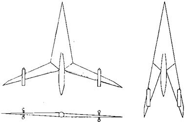
Another rotation-only variable-sweep concept was invented by the late Robert T. Jones at the NACA Ames Aeronautical Laboratory, around 1945 (Figure 16.3). This is the oblique or skewed wing, in which wing sweepback (and sweepforward) is achieved by rotating the wing at its center, sweeping one side back and the other side forward. With the oblique wing rotated back into symmetry, the configuration avoids the tip stalling and low-speed stability and control problems associated with ordinary wing sweepback. Jones’ invention seems to have paralleled other rotating-wing sweep concepts, those of Lachmann of Handley Page and Richard Vogt of Blohm and Voss. Jones expected an additional advantage for the oblique wing as compared with conventionally swept wings, that of higher supersonic lift-drag ratio.

Had the unorthodox oblique-winged configuration been proposed by someone without Jones’ immense prestige, it might have been dismissed at once. But, for one thing, Robert Jones was credited with the invention of wing sweepback to alleviate compressibility ef­fects during World War II, independently of the Germans. He also contributed largely to stability and control theory, in all-movable controls, lateral control, two-control airplanes, and in solutions of equations of motion. Like the Wright brothers, Edward Heinemann, and John Northrop, Jones was not university-trained. His considerable mathematics were self-taught.

With the wing rotated, the oblique-wing configuration is that rarest of heavier-than-air machines, one without bilateral or mirror-image left-right symmetry Birds, dragonflies, and our own flying creations all have bilateral symmetry, as we ourselves do. It seems obvious that the flying qualities of an oblique-winged airplane would be strange, if not dangerous. For one thing, pulling up the airplane’s nose to increase angle of attack would create inertial rolling and yawing moments, quite absent in symmetrical airplanes. These moments arise from pitching velocity and acceleration acting on a nonzero product of inertia term Ixy.

The Oblique or Skewed Wing

Figure 16.3 Robert T. Jones, ahead of his time in many areas of aeronautics. He was the inventor in the United States of wing sweepback and of the oblique-winged airplane. Jones contributed to stability and control theory in lateral control, in two-control airplanes, and in all-movable controls. (From Hansen, Engineer in Charge, 1987)

The effectiveness of trailing-edge flap-type controls is seriously reduced at large sweep or skew angles. Control deficiencies can be made up if the airplane carries conventional tail surfaces. Control problems are more critical if an oblique wing airplane is always operated in the skewed position, but this would obviate the need for rotating engine pods and vertical tail surfaces.

Wing torsional divergence on the sweptforward panel, discussed in Chapter 19, “The Elastic Airplane,” has been raised as an issue for the oblique wing. Jones quite early predicted that rigid-body roll freedom would tend to raise the divergence speed to safe values outside of the flight range. That is, when the leading or sweptforward panel starts to bend upward under high airloads, the lift on that panel would increase, causing a large rolling moment. Airplane roll response to that moment would alleviate the airload and the wing would be safe.

However, the case must be considered in which automatic roll control operates to hold the airplane at zero bank. If the control rolling moment that holds the zero-bank angle comes from a horizontal tail, the wing torsional divergence speed could be close to the body-clamped case. A free-free analysis that includes autopilot loops would seem to be needed. On the other hand, if control rolling moment comes from ailerons on the leading panel, the panel loads would be reduced, as in the case of free-body roll. This would raise torsional divergence speed above the body-clamped value.

Some detailed stability and control data on oblique wings were obtained in NASA Ames Research Center wind-tunnel tests and in a NASA-Navy funded study begun in 1984. The

The Oblique or Skewed Wing

Figure 16.4 Zero-sideslip variations of rolling moment and side force coefficients for an oblique wing tested on a model of the NASA-Vought F-8 research airplane. Sizable, nonlinear values appear for wing skew angles of 30 degrees and above. (From Kroo, AIAA Short Course Notes, 1992)


study was on the feasibility of converting NASA’s F-8 Digital Fly-By-Wire Airplane to an oblique wing configuration. A key problem surfaced in the unusual nonlinear variations at zero sideslip angle in side force, and rolling and yawing moments with angle of attack, at wing skew angles as low as 30 degrees (Figure 16.4). These are trim moments, which would have to be trimmed out by control surface deflections for normal, nonmaneuvering flight. The nonzero side force could be equilibrated by flying at a steady bank angle, or possibly by wing tilt with respect to the fuselage.

Other possibilities to deal with nonzero side forces, yawing, and rolling moments at zero sideslip include wing plan form adjustments, unsymmetrical tip shaping, wing pivot selection, antisymmetric wing twist, and variable tip dihedral (Kroo, 1992). One is left with the impression that the aerodynamic design of a practical oblique-wing airplane will be far more complex than for its swept-wing counterpart.

There have been a number of oblique-wing flight tests, starting with a test in the Langley Research Center’s Free Flight Wind Tunnel. R. T. Jones also built and successfully flew a

The Oblique or Skewed Wing

Figure 16.5 The R. T. Jones invention in flight, the Ames-Dryden AD-1 oblique-wing testbed, flying with its adjustable wing in the fully swept 60-degree position. (From Hallion, NASA SP-4303, 1984)

The Oblique or Skewed Wing

Figure 16.6 The Vickers-Armstrong “Swallow” variable-sweep concept, tested at NASA’s Langley Laboratory and found to be longitudinally unstable with wings unswept. (From Polhamus and Toll,

NASA TM 83121, 1981)

series of small free-flying oblique-winged model aircraft, culminating in a radio-controlled two-meter span model whose wing andtailplane skew angle could be systematically changed in flight. A considerable number of oblique-wing design studies followed. NASA eventually contracted to have a full-scale oblique-wing test airplane built for low-speed flight tests. This airplane, the AD-1, a single-engine jet, was flown successfully at the NASA Dryden Flight Research Center at Edwards, California (Figure 16.5). Ten degrees of bank angle on the AD-1 are required to cancel the side force produced by a 60-degree wing skew angle (Kroo, 1992).

The Dryden flight tests were followed by a NASA design research contract for an oblique­wing supersonic transport. The contract was awarded to Boeing, McDonnell-Douglas, and Kansas University, around 1992. The study revealed arrangement problems with that partic­ular arrangement. An all-wing version of the oblique-wing eliminates the need for hinging the wing to a fuselage, although engine pods and any vertical tails still require hinging. Another NASA design research contract to Stanford University is for a flying model of a 400-foot-span all-wing supersonic transport, operated as an oblique wing. Stability and control for the all-wing versions of the oblique wing are problematic because of the problem of nonzero side forces, rolling, and yawing moments in oblique cruising flight.

The Semirigid Approach to Wing Torsional Divergence

In the semirigid approach to wing torsional divergence and related problems a reference section of the wing is selected to represent the entire three-dimensional wing. This simplification works quite well for slender wings, that is, wings of high-aspect ratio.

Semirigid analyses of wing torsional divergence are given in a number of textbooks (for example, Duncan, 1943; Fung, 1955). Fung shows a wing section that rotates about a pivot and is acted upon by a lift load. The pivot represents the chordwise location in the section of the wing’s elastic axis, or location where lift loads will not produce twist. The lift load can be taken as acting through the section’s aerodynamic center. The aerodynamic center, near the section’s quarter-chord point, is the point about which section pitching moments are invariant with angle of attack (Figure 19.1).

The wing section will come to a static equilibrium angle at some angle of attack under the combined action of the lift load and a spring restraint about the pivot. The spring restraint represents the wing’s elastic stiffness. If the pivot, representing the elastic axis, is behind

The Semirigid Approach to Wing Torsional Divergence

Figure 19.1 Semirigid model forwingtorsional divergence. Thewingis replacedby atypical section, pivoted aboutapoint that represents the wing’s elastic axis. The spring represents elastic stiffness. Inthis illustration, the wing’s aerodynamic center, where the lift acts, is forward of the pivot point. Increasing airspeed eventually leads to a torsional divergence. The angle of attack a increases without limit. (From Fung, The Theory of Aeroelasticity, Dover, 1969)

the wing’s aerodynamic center, the equilibrium angle of attack increases with increasing airspeed, which gives higher wing lift loads.

For any eccentricity, or distance of the aerodynamic center ahead of the pivot, and for given spring constants and wing lift curve slopes, or variations of wing lift with angle of attack, there is an airspeed at which the semirigid model diverges. That is, the equilibrium solution fails. Twist angle and angle of attack increase without limit. This is the calculated wing torsional divergence speed.

Wing torsional divergence problems were encountered on the Republic F-84 and Northrop F-89 airplanes, both equipped with large tip tanks (Phillips, 1998). Fixed fins on the outside rear of the F-84’s tanks moved the wing’s aerodynamic center aft, eliminating the problem.

Linear Quadratic Gaussian Controllers

Linear quadratic Gaussian (LQG) controllers add to the linear quadratic (LQ) designs random disturbances and measurement errors. LQG designs are discussed at length in a 1986 text and a 1993 IEEE paper by Professor Robert F. Stengel. The form taken by

Linear Quadratic Gaussian Controllers

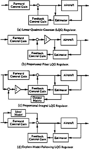
Figure 20.8 Various control system forms that can be represented with the structured linear quadratic regulator(LQG)method. (FromStengel, IEEE Trans. onSystems, Man, andCybernetics, © 1993 IEEE)

the discrete-time LQG optimal controller is

uk = CFyk* – CBxk,

where yk * is the desired value of an output vector and xk is the Kalman filter state estimate.

The LQG design approach is very flexible because of the number of parameters that can be chosen arbitrarily. At one extreme, a scalar one-input, one-output design can be produced. Measurement and control redundancies can be represented if measurement and control vector sizes exceed that of the state vector. Also, integral compensation and explicit model-following structures can be produced (Figure 20.8).

LQG designs are among the most advanced to be in use by stability-augmentation en­gineers, as this is written. Even more advanced control concepts continue to pour out of university and other research centers. The same 1993 paper by Stengel cited above provides a good survey of advanced control concepts, including expert systems, neural networks, and intentionally nonlinear controls.

20.3 Failed Applications of Optimal Control

The failure of optimal control methods to produce a satisfactory flight control system for the Grumman X-29A airplane was noted in Sec. 14. This failure is by no means an isolated event. Additional instances can be found in which optimal control methods in the hands of experienced engineers have failed to produce safe and satisfactory flight control systems. What has gone wrong? Several experts who have witnessed these failures discuss the problem:

Phillip R. Chandler and David W. Potts (1983), U. S. Air Force Flight Dynamics Laboratory “[T]he infinite bandwidth constant compensation elements which are required [for LQR] violate the very heart of the feedback problem. . . . LQR therefore is an elegant mathematical solution to a nonengi­neering problem SVT (Singular Value Theory) [Doyle, 1979] is a very crude

method of coping with uncertainty in the LQR or LQG procedure. It makes assumptions that are not valid for flight control_______________________________________ LQR with all its ramifica­

tions and refinements is totally unsuited for the flight control servomechanism problem.”

John C. Gibson (2000), formerly with English/Electric/British Aerospace

“[Robert J.] Woodcock told me that there have been several missile and aircraft projects in serious trouble due to the use of such [LQG] methods_______________________________________ While op­

timization methods are continually being improved, they cannot yet (and may never) guarantee a safe and satisfactory FCS [flight control system] design with­out the strictest guidance and detailed physical understanding of experienced control and handling qualities engineers. This is true for highly advanced and demanding types of aircraft. Every signal path must be clearly visible and eas­ily related to specific aerodynamic or inertial characteristics of the airframe. In simple aircraft without complexity, there is no advantage over straightforward engineering methods anyway.”

Michael V. Cook (1999, 2000), Senior Lecturer, Cranfield University “There exists an enormous wealth of published material describing the application of so-called, ‘modern control methods’ to the design of flight control systems for piloted aeroplanes. It is also evident, with the exception of a very small number of recent applications, that there is a conspicuous lack of enthusiasm on the part of the airframe manufacturers to adopt this design technology, especially for the design of command and stability augmentation systems for piloted airplanes. Having an industrial background I am well aware of the many reasons why modern control has not been taken onboard seriously by the manufacturers – academic control specialists don’t share my view, and in many cases probably don’t even understand it!… I know that my views are shared by the control

people in——- who, in private are not at all complimentary about the academic

control specialists in the UK. I am also aware that the Boeing view is similar to

that of—— . I’ve seen some appallingly bad control systems design theses (not

from Cranfield).”

Steven Osder (2000), Osder Associates, Arizona “We [Osder and Dunstan Graham] used to lament the absurdity of papers [on robustness theory] that were filling the journals and we amused each other by citing specific examples of such departures from reason and logic_____________________ At the [Boeing] helicopter com­

pany, we took each of those University of – [robust flight control] designs and tested them against more complete [nonlinear] models of the [Apache] aircraft.

In every case, these robust flight control designs always fell out of the sky. In one case [which used eigenstructure assignment], even testing against a lin­ear model, but with only a 10 percent variation in a single B [control] matrix term, our simulations resulted in a crash.”

Duane T. McRuer (2001), Chairman, Systems Technology, Inc. “At STI we have spent an enormous amount of time and effort searching for ways to make optimal control practical – at least 20 major reports and papers, with some tremendously capable folk (e. g., Dick Whitbeck, Greg Hofmann, Bob Stapleford, Peter Thompson, et al.). Our focus has been on finding performance indices, special schemes, etc., to make optimal control solutions jibe with good

design practice__ We have just never been happy with the results for stability

augmentation design.”

In the light of the foregoing comments, a design case (Ward, 1996) in which an LQG design for a pitch stability augmentation system was used only as a guideline for a more conventional approach suggests a reasonable use for optimal control techniques. The concept of using LQR optimal control synthesis as a guide or in conjunction with classical methods is also developed by Blight (1996). Blight also comments that LQR methods should be used only on “control problems that actually require modern multivariable methods for their solution.” For example, Blight recommends ordinary gain scheduling instead of attempting to design a single robust linear control law for all flight conditions.

World-Wide Flying Qualities Specifications

As mentioned earlier, the German air forces in World War II operated under a set of military flying qualities requirements related to the Gilruth set of 1943. The growth of civil aviation after the war led to a number of national and world-wide efforts to specify flying qualities requirements, in order to rationalize aircraft design and procurement in each country and the international licensing of civil aircraft. The goal of internationally agreed upon civil aircraft flying qualities standards is the responsibility of the International Civil Aviation Organization (ICAO), an arm of the United Nations. Annex 8 of the ICAO Standardsdealswith airworthiness, which includesadequate flying qualities(Stinton, 1996).

Standards have also been adopted by individual countries for both civil and military machines. An earlier section traced the evolution of U. S. flying qualities specifications for military aircraft. Similar evolutions took place all over the world. British military specifi­cations are in the UK DEF STAN publications. In particular, DEF-STAN 00-970, issued in 1983, is similar in style to MIL-F-8785C and provides much the same information (Cook, 1997).

British civil flying qualities requirements were embodied initially in the BCARs, or British Civil Airworthiness Requirements. European standards now apply, as found in the European Joint Aviation Requirements, or JARs, issued by the Joint Aviation Adminis­tration. The U. S. versions are the Federal Air Regulations, or FARs, parts 21, 23, 25, and 103 of which deal with airplanes. The wording of the stability and control airworthiness requirements of the FARs is similar to the Gilruth requirements of 1943, which were also concerned with minimum rather than optimum requirements.