Category Airplane Stability and Control, Second Edition

Wind, Body, Stability, and Principal Axes

One of the most distressing experiences for beginning stability and control en­gineers is to be faced with at least four alternate sets of reference axes for the equations of airplane motion. The original Bryan set, called body axes, is perhaps the most easily

Wind, Body, Stability, and Principal Axes

Figure 18.6 Representative lateral-directional stability boundaries. Spiral and directional divergence boundaries are given, along with approximations for Dutch Roll period and damping. The airplane relative density і is used in the chart coordinates. (From Zimmerman, NACA Rept. 589, 1937)

grasped. Orthogonal reference axes are fixed in the airframe as if they were painted on, remaining in place through all subsequent motions. To be fair, even body axes can migrate with respect to the airframe, since the most common form has its origin at the airplane’s center of gravity, which shifts about with different loadings.

Body axes have the practical virtue that the variables of motion that are calculated, such as the linear and angular velocities, are easily related to the readings of flight instruments, which are, after all, also fixed to the body. However, in the early days of stability and control analysis, there were advantages to wind axes (Zimmerman, 1935).

In wind axes, the forward or X-axis points into the wind during the entire motion, rotating about the center of gravity with respect to the airframe. The independence of translatory and rotational motions allows this to happen without affecting the calculation of pitching motions. An advantage of wind axes is that the X and Z forces are the exact negatives of the familiar drag and lift forces presented in wind-tunnel test reports and used in airplane performance calculations.

Stability axes came into the picture in the 1940s, as a device to simplify calculation of small-perturbation airplane motions. Stability axes are a special set of body axes. The X stability axis points into the relative wind in the equilibrium flight that precedes the disturbed motion, but remains fixed in the body during the calculated motions around equilibrium. All that is accomplished by stability axes is the elimination of a few terms in the equations that include initial angle of attack. With the advent of powerful new digital computers stability axes have become mostly a curiosity, except for the fact that the primed derivatives mentioned in Sec. 2 have their basis in stability axes. Duane McRuer notes that

Primed derivatives based on stability axes often have a remarkably simple connection with the basic motions of the aircraft…. [For example] the square of the Dutch roll undamped natural frequency is usually given to a high degree of accuracy by N^…. stability axes are appropriate for determining the characteristic modes [of motion] and their predominant constituents.

To complicate things, the term stability axes sometimes has quite another meaning than that of a special set of body axes for flight dynamics studies. Wind-tunnel data are quite often produced in what are called stability axes, but for clarity should be named wind-tunnel stability axes. The Z-axis is in the plane of symmetry and normal to the relative wind; the X-axis is in the plane of symmetry and is normal to the Z-axis; the Y-axis is normal to both X – and Z-axes.

Principal axes are another curiosity in present-day practice, since they are used only to eliminate the product of inertia terms in the equations of motion. As with stability axes, principal axes have been obsoleted by powerful digital computers. A few added terms in the equations seem to add nothing to computing time.

The hybrid case in which wind axes are used for the three force equations and body axes for the three moment equations can be found in some simulations. The first hybrid application the authors are aware of was made by Robert W. Bratt at the Douglas Aircraft Company’s El Segundo Division, about 1955, in connection with inertial coupling studies. A more recent example of hybrid axes is NASA’s SIM2, which actually uses three sets of axes, wind, wind-tunnel stability, and body (Figure 18.7). SIM2 was first put to use at the NASA Dryden Flight Research Center for real-time digital simulation of the McDonnell Douglas F-15. The aerodynamic data base was filled in to an angle of attack of 90 degrees, to allow simulation of stalls and spins. Later SIM2 applications were to the space shuttle Orbiter and to the Northrop B-2 stealth bomber.

With three axes systems carried along simultaneously in the solution, the angular rela­tionships among the SIM2 axes sets must also be continuously computed. The fundamen­tal force vector equation on moving axes used in SIM2 uses the vector cross-product of angular velocity of wind axes and the velocity vector. A key vector equation solves for the angular velocity of wind axes as the angular velocity of body axes minus two terms, the angular velocity of wind-tunnel stability axes with respect to wind axes and the angular velocity of body axes with respect to wind-tunnel stability axes.

Wind axes differ from wind-tunnel stability axes only by a positive sideslip angle rotation about the Z stability axis, so that the second of the three terms in the vector equation for wind axes angular velocity has only one nonzero element, the sideslip angle rate. Likewise, wind-tunnel stability axes are derived from body axes by a single angle of attack rotation

along the negative Y-body axis. The required vector transformations are made in component form, always taking care to add components in the same axis systems.

The sideslip and angle of attack variables that define the difference among the three axis sets in SIM2 have one of the two possible definitions. The SIM2 convention happens to agree with the most common definition, in which wind axes are derived from body axes by an initial negative angle of attack – a rotation followed by a positive sideslip angle rotation в (Figure 18.8). The reverse convention is rare but not unknown.

Extended airplane axes sets that allow for flight at extreme speeds and altitudes, taking into account the earth’s actual shape, are treated in Sec. 15.

Automatic Pilots in History

Stability augmentation goes back only to about 1945, while the history of airplane and missile automatic pilots, or autopilots (that word happens to be a trademark of a par­ticular manufacturer), actually begins before the Wright brothers, with Sir Hiram Maxim’s 1891 designs. That history has been told by several authors, including Bollay (1951) and the scholarly but very readable account of automatic pilot development in the first chapter of Aircraft Dynamics and Automatic Control by McRuer, Ashkenas, and Graham, dated 1973.

An additional historical account of airplane automatic pilots is that ofW. Hewitt Phillips, in his Dryden Lecture in Research (1989). All of these authors refer to the remarkable 1913— 1914 demonstration of the Sperry “stabilizer,” which provided full automatic control of a Curtiss Flying Boat. However, the present chapter deals only with stability augmentation.

Gust-alleviation systems are a specialized form of airplane automatic pilots, designed to reduce structural loads and to improve ride quality in rough air. These systems are of less interest now than formerly because modern airplanes can fly above turbulence or use weather radar to avoid storms. A complete historical review of gust-alleviation systems is available in a NASA Monograph (Phillips, 1998).

Faceted Airframe Issues

The Lockheed F-117A’s faceted airframe flies in the face of conventional aero­dynamic wisdom, which requires smooth surfaces to maintain attached flow under the widest possible ranges of angles of attack, sideslip, and angular velocities (Figure 22.1). On the other hand, the aerodynamic forces and moments of faceted airframes are reasonably linear functions of these variables for sufficiently small ranges.

Large-wing sweepback, 67 1/2 degrees in the case of the F-117A, extends the linear ranges somewhat, making facet edges into side edges instead of breaks normal to the flow direction. Still, the stability and control engineer who is faced with a faceted airframe such as the F-117A must expect to restrict flight parameters in order to avoid nonlinear and unstable aerodynamic moments that exceed available control power. The F-117A was originally called “The Hopeless Diamond” by Lockheed aerodynamicists.

Faceted Airframe Issues

Figure 22.1 Faceted structure of the Lockheed F-117A Stealth Fighter. (From Lockheed Advanced Development Company, J. W. Ragsdale)

On the F-117A, the angle of attack is hard-limited, but sideslip angles are unlimited with the landing gear down for cross-wind landings. With landing gear up, the sideslip angle is nulled by closed-loop control, a normal loop closure. F-117A longitudinal static margins are low or negative within the angle-of-attack limit range, but air combat maneuvers can be made within that range. Severe pitchups and pitchdowns occur outside of the angle-of-attack limit range (Farley and Abrams, 1990). Without augmentation, the airplane is directionally unstable over large parts of its operational envelope.

The four F-117A elevons have relatively large travels of 60 degrees up and down, which are necessary to deal with nonlinear and unstable moments within the angle-of-attack limit range. The two vertical tails are all-moving, for the same reason. The F-117A has quadruple fail-safe fly-by-wire controls, using F-16 technology. An 18-foot-diameter brak­ing parachute doubles as a spin chute, an unusual feature for a service airplane. Nominal landing speed is 160 knots, at an angle of attack of 9 1/2 degrees.

Bleriot and Deperdussin Controls

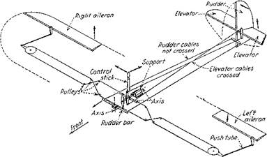
Louis Bleriot devised what has become the standard stick and rudder cockpit controls for small airplanes. A central stick between the pilot’s legs is moved forward for nose down, aft for nose up, to the left for left wing down, and to the right for right wing down. The pilot’s feet rest on a rudder bar from the ends of which a pair of cables run straight back to the rudder horns. Thus left foot forward deflects the rudder to the left and turns the machine to the left (Figure 1.3). Bleriot fitted a nonrotatable wheel to the top of the control stick, perhaps to give the pilot a firmer grip for wing warping.

The Bleriot rudder pedal convention, now quite standard, is just the opposite of bicycle or “Flexible Flyer” sled steering, where operators turn the handlebars or hand grips in the direction of the desired turn. Igor Sikorsky thought that the Bleriot convention was backward. Sikorsky crossed the rudder wires on all of his airplanes, to make them steer like bicycles. He warned conventionally trained pilots not to try to fly these particular machines.

Before the war, the company Societe pour Avions Deperdussin (SPAD) produced a series of military airplanes and racers that were designed by Bechereau. These streamlined airplanes were fitted with Bleriot-style rudder bars and a vertical wheel that could be moved fore and aft for pitch and turned sideways for wing warp. The wheel’s increased mechanical

Bleriot and Deperdussin Controls

Figure 1.3 Diagrammatic sketch of a simple airplane control system. When the controls are moved as shown by arrows on the stick and rudder bar, the surfaces move as shown by the arrows. (From Chatfield, Taylor, and Ober, The Airplane and Its Engine, McGraw-Hill, 1936)

advantage as compared with levers was needed to warp wings of increased torsional rigidity. The Deperdussin wheel is the ancestor of modern control yokes.

Propeller Slipstream Effects

Of all the propeller or jet power effects on stability and control, those due to the propeller slipstream or wake are the most difficult to deal with, analytically or in test. The British engineer William Froude (1810-1879) laid some initial groundwork in his application of momentum theory to establish propeller (or ship screw) slipstream veloc­ity. But the nominally cylindrical slipstream is distorted badly as it passes over wings and fuselages. As a result, slipstream effects on wings, tails, and fuselages are difficult to predict. The Smelt and Davies (1937) and Millikan (1940) papers are fair starts on pre­diction, but most designers still rely on educated guesses, based on test data from earlier projects.

A few generalities exist for propeller slipstream effects on static longitudinal stability. The relative increment in slipstream velocity over that of the free stream increases as airspeed is reduced, at fixed throttle setting. If the horizontal tail carries a net down load and is exposed to the slipstream, relative higher velocities as airspeed is reduced increases that down load, pitching the airplane nose up, a destabilizing effect.

Therefore, net down tail loads on propeller-driven airplanes, such as are required to trim out landing flaps, are destabilizing under power-on conditions. This effect is avoided only if the horizontal tail is mounted high enough on the vertical tail so as to be out of the propeller slipstreams at all angles of attack. Although down-load destabilization must have been known to designers before 1948, the first discussion of this effect published in the United States dates from that year (Phillips, 1948).

In addition to down tail load destabilization, increased downwash at the horizontal tail due to power is also a destabilizing factor. This factor was also first noted by Phillips. A semiempirical correlation of the increased downwash due to running propellers was made shortly afterwards by Weil and Sleeman, based on the power-off downwash and the propeller’s thrust coefficient (Figure 4.4).

Rotation of the slipstream behind propellers of single-engine airplanes creates side loads on vertical tails at low airspeeds, requiring that pilots apply counteracting rudder deflections to hold a straight course. This can be unnnerving at high power levels, such as in takeoff runs and in waveoffs from carrier landings. Some manufacturers offset fin leading edges to the left for U. S. right-hand propeller rotation when viewed from the rear, to minimize required rudder angles at high power levels and low airspeeds.

However, offset fins result in large and rapidly changing rudder pedal forces in high­speed dives, requiring high pedal forces to stay on a dive-bombing target. On the other hand,

Propeller Slipstream Effects

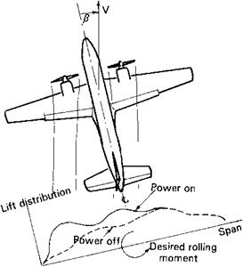
Figure 4.5 Unstable dihedral effect (forward-wing-down) due to slipstream loads.

lateral offset of an airplane’s center of gravity is effective in reducing the rudder deflections required for trim under high power conditions while causing only a constant, rather than a rapidly, increasing pedal force to trim in dives (Phillips, Crane, and Hunter, 1944). The U. S. Navy seems not to have asked builders of high-powered propeller carrier airplanes to offset their centers of gravity to the right, except for the carriage of unsymmetric loads. Phillips comments:

The interesting thing about this corrective measure is that all the effects produced (direct thrust moment, aileron yaw, fuselage side force, and rudder side force) are changed in the correct direction to reduce the rudder deflection for trim.

According to the publication WWI Aero, the center of gravity offset effect on rudder trim with high power seems to have been known to World War I airplane designers, such as Anthony Fokker.

An additional propeller slipstream effect on stability is a reverse dihedral effect at high angles of attack. This is an easily visualized geometric effect (Figure 4.5). Sideslip de­flects the slipstream toward the leeward or trailing wing, increasing its lift relative to the windward or leading wing. This creates a destabilizing rolling moment due to sideslip, or a negative dihedral effect. This phenomenon necessitated rebuilding the prototype Martin 202 airliner so that its original one-piece wing was cut apart outboard of the nacelles and reassembled with more dihedral in the outer panels, a modification that nearly bankrupted the company.

Layout Principles

6.1.1 Subsonic Airplane Balance

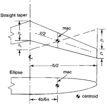
Subsonic tail-last (not canard) airplanes are generally balanced to bring their cen­ters of gravity near the wing-alone aerodynamic center. This is the point at which the wing’s pitching moment coefficient is invariant with angle of attack. For reasonably high wing aspect ratios, the wing-alone aerodynamic center is near the 25-percent point behind the leading edge of chord line passing through the wing’s center of area. This chord line is called the wing’s mean aerodynamic chord or mac. Figure 6.1 shows the simple geometric construction defining the mac for straight-tapered and elliptical wings.

Tailless airplanes must have their centers of gravity ahead of the wing aerodynamic center or 25-percent mac point to be inherently statically stable. If the wing is swept back, it can be trimmed at a reasonably high lift coefficient with trailing-edge-up deflections of its elevons. The degree of static stability desired and the maximum lift coefficient ob­tained are interrelated. Tailless airplanes can have their centers of gravity behind the wing

Layout Principles

Figure 6.1 Geometrical constructions for the mean aerodynamic chord (mac) on straight-tapered and elliptical wings.

aerodynamic center if static stability is provided by artificial means or stability augmentation (see Chapter 20). Longitudinal trim then requires trailing-edge-down elevon. This increases effective wing camber, with beneficial effects on performance (Ashkenas and Klyde, 1989).

The canard configuration, abandoned after 1910 by its inventors, the Wright brothers, has been revived in recent years, notably by Burt Rutan, in the belief that the arrangement provides natural stall prevention (see Chapter 17, Sec. 2). Also, trimming with an upload is thought to reduce induced drag, although this has been disputed. The neutral point, or center of gravity for neutral stability, of canard airplanes is considerably ahead of the 25-percent point of the wing mac. On the Rutan machines, fuel tanks are fitted in triangular leading-edge extensions to keep the fuel near the airplane’s center of gravity.

Rotary Balances and the Steady Spin

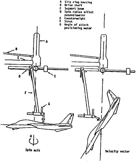
Rotary balances are designed to extract rotary derivatives from wind-tunnel tests. The model is typically held at some fixed angles of attack and sideslip to the relative wind and rotated by an electric motor at a fixed rate (Figure 9.6). Combined aerodynamic, gravity, and inertial forces and moments are measured by a six-component balance internal to the model. The desired aerodynamic forces and moments are obtained by subtracting the other components, as tares. Rotary balance tests in which angles of attack and sideslip remain constant are called “coning tests.” The spinning axis is aligned with the tunnel flow direction for coning tests.

Rotary balance testing actually predates the free-spinning tunnel, with E. F. Relf and T. Lavender’s 1922 and 1925 measurements in Britain. An earlier paper (Relf and Lavender,

Rotary Balances and the Steady Spin

Figure 9.6 The NASA Langley Research Center’s current spin tunnel rotary balance rig. The electric motor that spins the model is outside the tunnel. At the left, a model in a flat-spinning orientation; a normal spin orientation is at the right. This is believed to be the only rotary balance in current (early 1990s) use at Langley. (From Bihrle and Chambers, AGARD AR 265, 1990)

1918) described some of the first tests on autorotating wings. Autorotation is wing negative damping in roll, at angles of attack beyond the stall. Autorotation provides a driving or propelling moment in spins.

Until the coming ofthe jet airplane and the oscillatory spin, the chiefuse of rotary balance testing was in finding the steady spin modes of an airplane. That is, would spins be steep, or easily recoverable, or fast and flat, with problematic recoveries? The pioneering rotary bal­ance work of thistype wasdone by P. H. Allwork using the NPL 7-foot wind tunnel in Britain, and Millard Bamber and Charles Zimmerman in the NACA 5-foot vertical wind tunnel.

With simplifying assumptions, the three force equations of the ordinary 6-degree – of-freedom equations of airplane motion reduce to only two equations, which are not simultaneous with the three moment equations. Under steady conditions, angular accel­erations drop out. With aerodynamic data from rotary balance coning tests, the remaining three simultaneous moment equations are fairly readily solved for the equilibrium spin.

The groundwork for equilibrium spin analysis was laid in a remarkable 1926 report by Sidney B. Gates and L. W. Bryant. The Gates and Bryant report was far ahead of its time, and quite comprehensive. A modern explanation of the mechanics of the equilibrium spin solution is given in William Bihrle, Jr.’s paper in Sec. 9.1 of AGARD Advisory Report No.265, dated 1990.

Principal Axis Inclination Instability

Lateral-directional dynamic instability due to nose-down inclination of the princi­pal axis is not strictly a high Mach number or compressibility phenomenon. However, this type of instability is linked to high-speed flight, and so it is included in this chapter.

The symmetric principal axis is defined as that airplane body axis in the plane of sym­metry for which the product of inertia Ixz vanishes. Mathematically, Ixz = f xz dm, where x and z are the X – and Z-axis coordinates of each elementary mass particle dm. Weights high on the vertical tail, such as a T-tail, cause the principal axis to be inclined nose-downward with respect to normal body axes.

A nose-down inclination of the principal axis with respect to the flight path desta­bilizes the lateral-directional or Dutch roll oscillation (Sternfield, 1947). Actual lateral – directional dynamic instability due to a nose-down inclination was encountered dramati­cally in May 1951 by the NACA test pilot Bill Bridgeman. This was in a series of flight tests of the Douglas D-558-2 Skyrocket research airplane. In tests reaching a Mach number of 1.79 serious rolling instability occurred during pushovers after rocket-powered steep climbs. The principal axis inclination to the flight path becomes quite nose-down during pushovers.

The test team evidently failed to connect the rolling instability with the principal axis effect and concluded that even higher speeds could be reached safely. Bridgeman was asked to nose over from the climb to a very low factor of 0.25, in an effort to reach a Mach number of 2.0. According to Richard Hallion (1981):

the Skyrocket rolled violently, dipping its wings as much as 75 degrees. He cut power, but the motions, if anything, became even more severe. Finally he hauled back on the control column, for the Skyrocket was in a steep dive and getting farther and farther away from the lakebed. The plane abruptly nosed up and regained its smooth flying characteristics, and he brought it back to Muroc.

However, concerns about Dutch roll instability due to principal axis nose-down inclina­tion have been eliminated by the almost universal use of yaw damping stability augmentation on high-speed airplanes.

1948 and 1966 NACA and NASA Test Series

Robert Gilruth’s codified requirements for satisfactory flying qualities of 1941 opened the way to apply flying qualities technology to the safe airplane problem. Paul A. Hunter made the first NACA flying qualities measurements specifically on personal-owner airplanes in 1948. This was followed by a second test series on light airplane flying qualities (Barber, Jones, Sisk, and Haise, 1966).

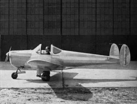
The seven light airplanes tested in 1966 were bigger, heavier, and more complex than the group of five looked at in 1948. Four of the seven were twin-engined; the single-engine ships were the straight and vee-tailed Beech Bonanza and a 285 HP Cessna Skylane RG. In keeping with NASA’s practice at that time, data presented are not identified as having come from specific airplanes.

Reported flying qualities problems ranged from rather trivial trim change difficulties to more serious issues. As in the case of the Spitfire and DC-3 (Chapter 3), static lon­gitudinal instability was present for some of these airplanes within their normal loading ranges, especially with flaps down and high power settings. Bobweights and downsprings provided stable force gradients in some cases, without improving stick-fixed stability. Low Dutch roll damping reduced the accuracy of instrument approaches in turbulence (Figure 15.4).

Dangerous stalling characteristics were encountered in the tests. Quoting from the Barber report:

1948 and 1966 NACA and NASA Test Series

Figure 15.3 The 1940 ERCO Ercoupe, as first produced. (From Weick, From the Ground Up, 1988)

Two of the aircraft tested have unacceptable power-on stall characteristics in the landing configuration. The lateral-directional trim changes of one aircraft show that the addition of power introduces a left yawing moment and that the pilot must use full right rudder to maintain heading when near the stall speed. The large yawing moment due to power coupled with the lack of rudder authority causes the aircraft to encounter an uncontrollable left roll/yaw motion at the stall. This motion places the aircraft in a spin that requires 600 to 1200 feet of altitude for recovery. All of the evaluation pilots exceeded the gear and flap placard speeds when recovering from this spin. Another aircraft has a rapid left rolloff in the power-on accelerated stall with landing flaps extended. The rolloff is difficult to stop in less than 60 to 70 degrees of left bank without anticipation and instantaneous recovery control on the part of the pilot. Such a stall may occur when a pilot tightens his final turn in the landing pattern to prevent overshooting the runway. From a left turn, the attendant rolloff, on occasion, proceeded to a nearly inverted attitude that required 200 to 300 feet of altitude to recover.

One is left to wonder how those two airplanes ever got to be certified as airworthy by the Federal Aviation Administration.

Stability and Control Issues with Variable Sweep

Variable wing sweepback is an attempt to combine the best performance, stability, and control characteristics of straight and swept wings. Straight wings have benign low – speed stability and control characteristics, good low-speed maximum lift, and low cruise drag, while sweptback wings have low transonic and supersonic drag and good high-Mach – number stability and control. In a variable-sweep airplane, wings are spread fully, orunswept, at low speeds and are swept back at high Mach numbers.

16.1 The First Variable-Sweep Wings – Rotation and Translation

The designers of the first variable-sweep airplanes, the Messerschmitt P1101, the Bell X-5, and the Grumman XF10F-1, found it necessary to move the wing inboard ends forward on the fuselage as the wing tips were moved aft. This was to keep the wing’s mean chord in about the same fore-and-aft position along the fuselage. This kept the distance from the airplane’s cg to the wing aerodynamic center about the same as the wing was swept back.

It can be imagined that the complication of a wing-fuselage attachment that translated as well as rotated was a powerful deterrent to aircraft designers. In fact, while this was the only available variable-sweep method, the concept turned up only in research aircraft.