Category Airplane Stability and Control, Second Edition

The F4D Skyray Experience

At the Douglas Aircraft Company’s El Segundo plant the F4D (later F-6) Skyray was being delivered in service test quantities at the height of the inertial coupling excitement. While it was becoming clear that the coupling problem could be eased, if not avoided, by artificial pitch and yaw damping, these devices were still heavy and unreliable. In any case, properly applied, they are placed in series into a control circuit. That is, artificial damping devices are not a parallel installation, as are many automatic pilots, but are an integral part of the control run from stick to control surface. A series-type artificial damping device cannot be easily retrofitted to a production airplane.

The F4D Skyray Experience

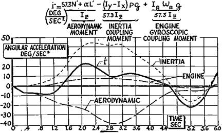
Figure 8.7 The relative importance of aerodynamic, inertial coupling, and engine gyroscopic terms in yawing acceleration during a rapid roll in the North American F-100. In this example, aerodynamic moment is the major factor initially; then inertial coupling overpowers it. (From Wykes, WADC Conf. 56WCLC-1041, 1956)

High levels of static longitudinal and directional stability were likewise known to be helpful, increasing the roll rates that would cause coupling to occur. In the case of the tailless F4D, high levels of static longitudinal and directional stability could hardly have been designed into the basic airframe, even if the need had been known when the ship was laid out.

The only remaining option for the F4D at that stage was to determine safe maneuver limits, the points at which inertial coupling effects did not cause problems. The airplane could then be restricted by placard, with its pilots depended upon to operate within these limits. The problem of determining F4D safe maneuver operating limits fell into the hands of Robert W. Bratt, who was able to collect the large body of numerical data needed on Douglas Accounting Department digital computers.

The analog computers belonging to the Douglas Flight Controls Department could have in principle run the problem, except for two factors. First, the inertial coupling equations of motion include a large number of mathematical nonlinearities, such as trigonometric functions, needed to resolve gravity along airplane axes, and multiplications, needed to solve the Euler, or moment, equations. But representing nonlinearities on the analog computers of those days was a severe problem. The best analog trigonometric function generators and multipliers were small electromechanical servomechanism devices that were costly and somewhat slow. A few systems boasted “quarter-square” multipliers, which had no moving parts but were inaccurate.

The second drawback to having used analog computers for the F4D inertial coupling problem was that accuracy and repeatability were poor. Bratt’s problem was to cover systematically in small increments all combinations of lateral and longitudinal stick throws, including phasing or sequence between the two, trimmer settings, and airspeeds and alti­tudes, in order to establish the points of coupling onset. Vacuum-tube analog computers were not only subject to frequent breakdowns, but also to drifts and gain changes that could make a hash out of a systematic study. These considerations led to using the digital computer, an early use for these machines in flight dynamics.

The First Dive Pullout Problems

The Lockheed P-38 Lightning, a powerful and effective fighter airplane of World War II, is believed to have been the first airplane to have experienced adverse compressibility

The First Dive Pullout Problems

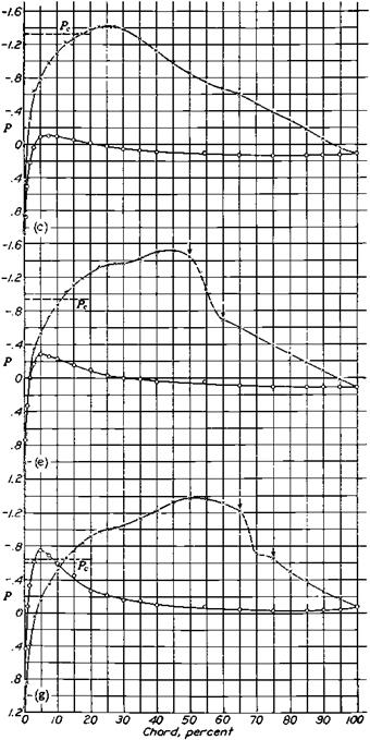
Figure 11.1 Pressure distributions on the NACA 4412 airfoil at an angle of attack of 1.9 degrees. From top to bottom, the Mach numbers are 0.60, 0.66, and 0.74. Separation, or the compressibility burble, starts at a Mach number of 0.66 on the upper surface areas between the arrows. (From Stack, Lindsey, and Littell, NACA Rept. 646, 1938)


effects on stability and control. A May 1942 Lockheed Company report by C. L. (Kelly) Johnson reported P-38 problems in dives and dive recoveries. These problems were typical of those found later in high-speed dives of other airplanes.

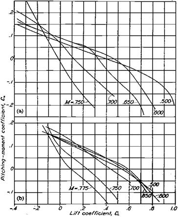
An important effect of compressibility on the P-38 was a great increase in the static longitudinal stability contribution of the horizontal tail. This was due to loss in lift curve slope of the thick center portion of the wing due to the compressibility burble. The P-38’s wing center section was the 15-percent-thick NACA 23015; the tip section was the 12-percent-thick NACA 4412. The reduced lift curve slope of the wing center section also re­duced the rate of change of downwash at the tail with angle of attack, accounting for the static longitudinal stability increase. Equally serious was a large nose-down trim change at the positive lift coefficients needed for pullouts from dives. Figure 11.2 shows both the increased stability and the trim change measured on a P-38 model in the NACA Ames 16-foot wind tunnel (Ericson, 1942).

Ericson and the NACA staff looked at fixes for these problems in a later series of 16-foot wind-tunnel tests that same year. The rather stubby P-38 fuselage aggravated the

The First Dive Pullout Problems

Figure 11.2 Variation of pitching moment coefficient with lift coefficient for two models tested in the NACA Ames 16-foot high-speed wind tunnel. Static longitudinal stability increases greatly at the higher Mach numbers and the trim lift coefficient (at zero pitching moment) is reduced. The upper data are for the Lockheed P-38, the lower for the Douglas DC-4 airplane. (From Hood and Allen, NACA Rept. 767, 1943)

The First Dive Pullout Problems

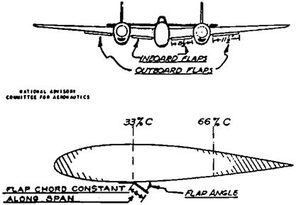
Figure 11.3 Dive-recovery flaps fitted to the Lockheed P-38 in the NACA 16-foot high-speed wind tunnel and later used on the P-38J-LO. (From Erickson, NACA WR-A-66, 1943).

problem by inducing high velocities over the already too thick wing center section, and some improvement was made when the model’s fuselage lines were straightened, by lengthening it. However, the most significant gain was made with lower surface auxiliary split-wing flaps, located 1/3 of the wing chord behind the leading edge (Figure 11.3). The auxiliary flaps, later to be called dive recovery flaps, increased the P-38’s trim lift coefficient by 0.55 at a Mach number of 0.725 (Ericson, 1943).

Best of all, auxiliary flap effectiveness decreases as the Mach number decreases. The importance of decreased effectiveness is that overcontrol is avoided during the dive recovery. Overcontrol in a dive recovery was a serious problem without dive recovery flaps, when pilots had only elevator control power to rely on to produce positive or nose-up pitching moments. In contrast to dive recovery flaps, pitching moment coefficient per degree of up- elevator travel actually increases as the Mach number decreases. Thus, if the pilot exerts a heavy pull force and nose-up trim through trim tabs to eke out a dive recovery against strong longitudinal stability and a nose-down trim change, when the Mach number drops and the latter two factors go away the airplane will respond to the heavy pull force and nose-up trim tab setting by making an excessively rapid pullout. If the normal acceleration or pullout g is high enough, the pilot blacks out and the wings fold upward.

The -25 block of the P-38J-LO series was fitted with dive recovery flaps. This same block of airplanes got power-boosted ailerons, further improving high-Mach-number con­trollability. Dive recovery flaps also were installed on P-47, A-26, P-59, and P-80 airplanes.

Control Surface Buzz

Control surface buzz is properly a single-degree-of-freedom flutter phenomenon, and thus not in the stability and control domain, but its cures affect controllability. Buzz was first encountered in dives on the Lockheed P-80 Shooting Star. Pilots reported strong, high-frequency lateral shaking of the control stick. Ordinary flutter was ruled out because calculations showed a reasonably high coupled wing-aileron flutter speed. The P-80’s wing is stiff, with 13-percent-thick NACA 65-series airfoils, and the ailerons are mass balanced. Moreover, the vibration frequency was higher than would be expected for structural modes.

The cause of the shaking turned out to be an aileron-alone mode, not involving wing bending or torsion at all. At Mach numbers where wing normal shocks perpendicular to the fuselage are in the vicinity of the aileron hinge line, shock position couples with aileron deflection to produce the motion. Trailing-edge-upward deflection of the aileron causes flow field changes that move the upper wing surface normal shock forward and the lower wing surface normal shock aft. This causes relative trailing-edge-down hinge moment, starting the aileron down and eventually reversing the shock wave upper and lower surface positions. This completes the cycle.

Clearly, control system flexibility plays a role in aileron buzz, permitting symmetric or in-phase aileron deflections. Restraining the aileron from symmetric rotations pre­vents buzz. The F-80’s control surface boost cylinder is on the airplane’s centerline. Control system flexibility from the centerline out to the ailerons is sufficient for buzz to occur.

The buzz fix for the P-80 and later airplanes with centerline aileron actuators was rotary hydraulic dampers installed at each aileron hinge. Damping is approximately proportional to control surface angular velocity, which is very high during high-frequency buzz but much lower for normal stick motions. Properly sized buzz dampers do not interfere with lateral controllability. Modern jet airplanes normally have irreversible hydraulic actuators located at each aileron. Aileron buzz is not a possibility for this arrangement.

Control surface buzz was a problem for the rudders of two subsonic jet airplanes of the 1950s, a late-model North American F-86 Sabre and the Douglas A4D Skyhawk. Both airplanes used splitter-plate or “tadpole” rudders to overcome buzz. Splitter-plate control surfaces are unskinned from about the midchord to the trailing edge, with loads borne by a central or splitter plate. The normal shock, whose fore and aft motion is central to control surface buzz, is stabilized at the abrupt surface break where the splitter starts. Another

Control Surface Buzz

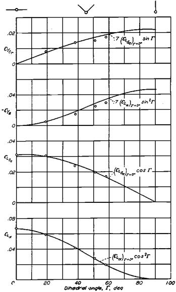
Figure 14.12 Experimental verification (small circles) for the Purser/Campbell vee-tail theory. Iso­lated tail stability and control contributions are plotted against tail dihedral angle. (From Purser and Campbell, NACA Rept. 823, 1945)

aerodynamic fix for control surface buzz is reported to be the addition of vortex generators just ahead of the control surface hinge line.

Other Canard Drawbacks

Canard surfaces usually reduce forward and downward visibility for the flight crew, a drawback in landing approaches and landings. A canard surface added to a conventional tail-last configuration results in three lifting surfaces in tandem. This is objectionable from an analysis and testing standpoint. That is, there are two downwash and sidewash fields to account for, adding to design and testing complexity.

Other Canard Drawbacks

Other Canard Drawbacks

Figure 17.3 A modern canard airplane, the SAAB JAS 39 Gripen. (From Jane’s AH the World’s Aircraft, 1987-1988)

Dihedral Effect of a Flexible Wing

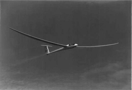
Dihedral effect Cle, the rolling moment due to sideslip, is determined chiefly by wing dihedral. However, the dihedral angle of airplanes with flexible wings varies noticeably according to the wing’s lift loads. Wing tips that droop when an airplane is parked can rise above the wing roots in flight, creating a positive dihedral angle. High-performance fiberglass sailplane wings bend upward alarmingly in flight, especially when the sailplane is in high-load-factor turns or pullups (Figure 19.7).

The first published analysis of the additional dihedral effect due to load factor showed a near doubling of dihedral effect for a wing of aspect ratio 10, at a hypothetical airplane’s limit load factor of 4.0. (Lovell, 1948). In a later published analysis of this effect, W. P. Rodden showed that measured aeroelastic effects on a flexible model of the Douglas XA3D-1 could be correlated with a simple theory that assumes a parabolic distribution of wing bending

Dihedral Effect of a Flexible Wing

Figure 19.7 Upward bending under airload of the flexible wings of a high-performance fiberglass sailplane. The bending adds to its effective dihedral angle. (Photo by Steve Hines)

(Rodden, 1955). This leads to a linear asymmetric spanwise distribution in additional angle of attack, as for the pure rolling case. An approximation to the flexibility increment to Cle is thus proportional to well-known roll damping derivative Clp values.

Rodden’s 1955 simplified analysis considers only the effects of symmetric air loads on wing bending. The analysis was extended to include the effects of asymmetric air loads (Rodden, 1965). Asymmetric loads cause an amplification of the dihedral angle. Ma­trix methods are used in this case, with aerodynamic and structural influence coefficients (Figure 19.8).

Crossover Model

The crossover model of compensatory operation grows out of the observation that pilots develop the necessary dynamics to produce in the pilot-airplane combination a particular transfer function in the crossover region of frequencies (McRuer, 1988). The pilot-airplane open-loop transfer function developed has the remarkably simple form of an integrated time delay, or rnc (e-Ts)/s, where the open-loop gain is rnc, т is the delay, and s is the Laplace operator. The open-loop gain rnc is called the crossover frequency, the frequency at which the open-loop amplitude response crosses the 1.0- or 0-db line.

The closed-loop frequency response, or ratio of output to input for the crossover model, is flat at 1.0 at low frequencies, meaning that the output follows exactly the input. As input frequency is raised, the frequency at which the output drops 3 db lower than the input, or to only 70 percent of the input, is considered a cutoff for all practical purposes. This frequency defines the closed-loop system bandwidth. For the crossover model, the frequency that defines closed-loop system bandwidth is also the frequency rnc for which the open-loop system has a gain of 1.0.

The crossover model time delay т is actually a low-frequency approximation, valid at crossover frequencies, for numerous pilot and control system delays and higher order lag terms. That part of т due to the pilot becomes greater as the lead contributed by the pilot increases, a cost of additional pilot effort (McRuer, 1988). This reduces the available crossover frequency for other system lags.

Stability and Control of World War I Pursuit Airplanes

By 1917 trial and error during the first World War had established the wire braced biplane with aft-tailed surfaces as the normal configuration. Diagonal brace wires between the wing struts and fuselage and within the wing frames made a torsionally rigid structure that resisted twisting and instability failure in high-speed dives. The heavy engine in front and the generous tail surfaces behind tended to keep the fuselage and wings aligned with the velocity of flight. The pilot could apply roll control by aileron deflection, yaw control by rudder deflection, and pitch control by elevator deflection – all independently. Aerodynamic hinge moments tended to center the controls. By ground adjustment of wing, fin, and tailplane rigging the airplane could be made to maintain level flight with cruising power in calm air for a minute or so.

Violent maneuvering in combat was provided mainly by the elevator, which had sufficient authority to bring the airplane to a full stall. Horizontal turning flight required rolling the airplane about its longitudinal axis quickly, which was most often accomplished by com­bined rudder and aileron deflection. The rudder-induced sideslip produced an unsymmetric stall and a snap or flick roll that could be checked at the desired angle by relieving stick back pressure and centering the rudder and ailerons.

The ailerons were difficult to deflect at combat speeds but could be used to produce a slow or barrel roll. An important use of the ailerons was to produce a cross-controlled (e. g., right rudder and left stick) nonrolling sideslip for glide path control while landing. The glide angle could be steepened appreciably by sideslipping in a steep bank, incidentally giving the pilot a good view of the touchdown point.

A dangerous aspect of stability and control of the otherwise benign World War I air­planes was inadvertent stalling and spinning at low altitudes, the so-called arrival and de­parture stalls (and spins). Moderate sideslip at stall would provoke a snap roll, which rapidly developed into the dreaded tail spin, or spinning nose dive. Generally there was insufficient room for recovery before ground contact.

Arrival stalls are still produced in modern airplanes by attempting to rudder the airplane around to the proper heading on final approach at a low speed without banking. The inner wing stalls and drops. The pilot attempts to pick it up with aileron deflection, which ag­gravates the situation. The airplane stalls and spins into the intended turn. The pilot who survives complains that the ailerons did not work.

Departure stalls are more spectacular. The pilot takes off from a small field. As the obstacles at the end of the field get near, with the engine at full power, the pilot rolls with the ailerons to a steep bank angle and turns away. The airplane has insufficient power to climb in steeply turning flight, so the pilot applies top rudder to hold up the nose. The resulting sideslip stalls the top wing, and the airplane performs an over-the-top snap roll and spin entry, followed by a fiery crash at full power.

Because of the stall-spin propensity of World War I airplanes, student pilots were given flight instruction on spin entry and recovery in airplanes with generally docile behavior. However, some airplanes, notably the Sopwith Camel, killed many student pilots because of its particularly vicious stalling characteristics. The Camel’s main fuel tank was behind the pilot, and the fully loaded center of gravity was so far aft that the airplane was unstable in pitch just after takeoff. Constant pilot attention was required to keep it from stalling.

Not only that, but, like many other World War I airplanes, the Camel’s vertical tail was too small. Any stall automatically became a snap roll spin entry, even without intentional rudder deflection. Finally, once spinning, the Camel required vigorous rudder deflection against the spin to stop the motion. A well-behaved airplane, on the other hand, has to be held in a spin; letting the controls go free should result in automatic recovery. Directional instability was so common among World War I airplanes that the Royal Air Force (R. A.F.) resisted closed cockpits for years so that pilots could use wind on one cheek as a sideslip cue.

Another dangerous feature of World War I airplanes was the gyroscopic effect of rotary engines. According to Gibson (2000), engine gyroscopic effect in the Sopwith Camel re­quired left rudder for both left and right turns and caused a departure if full power was used over the top of a loop at too low an airspeed. Pilots were warned to attempt their first hard right turns only above 1,000 feet.

Direct Propeller Forces in Yaw (or at Angle of Attack)

In contrast to the somewhat unsatisfactory state of the theory for propeller slip­stream effects, the theories for direct propeller forces in yaw are well established, and those theories were around as early as needed. According to Dr. Herbert S. Ribner:

It was realized as early as 1909 that a propeller in yaw develops a side force like that of a fin. In 1917, R. G. Harris expressed this force in terms of the torque coefficient for the unyawed propeller.

A1914 British R & Mby Relf, Bramwell, Fage, and Bryant presented experimental results onpropeller side forces. Two 1945 NACA reports by Ribner are usually taken as the definitive modern work on the subject. These reports provide a blade-element analysis applicable to any single – or dual-rotation system, sample calculations for two representative propellers with an interpolation scheme for other propellers, experimental verification of the blade – element method, and, finally, a remarkably simple rule-of-thumb side force estimate for preliminary design. This is to take the yawed propeller as a fin of area equal to the projected side area of the propeller. This fin’s effective aspect ratio is taken as 8, and the effective dynamic pressure at the fin is that for the propeller disk augmented by inflow. The side force for a propeller in yaw or sideslip is clearly the same as the propeller normal force at angle of attack.

For tractor airplanes, direct propeller forces in yaw act as a fin ahead of the airplane’s center of gravity. This is a major destabilizing contribution to static directional stability, especially at large propeller blade angles. The destabilizing effect depends on the propeller plane distance to the center of gravity, which is relatively greater for single-engine airplanes than for multiengine airplanes with wing-mounted engines. The same can be said for the effects of propeller normal force at angle of attack, in relation to static longitudinal stability. The classical NACA design method for satisfactory longitudinal stability (Gilruth, 1941) accounts for idling power effects using a propeller normal force calculation.

Tail Location, Size, and Shape

Horizontal and vertical tails are commonly located about a wing semispan behind the center of gravity. While horizontal tail sizes normally range from 15 to 30 percent of the wing area, the actual size is a complex function of desired center of gravity range, ground effect, and other factors. There is a minimum tail size that will trim a neutrally stable airplane at maximum lift in ground effect. Horizontal tails that are larger than this absolute minimum permit a useful operational center of gravity range.

Optimization theory has been proposed to size horizontal tails for particular center of gravity ranges, considering actuator rate and amplitude and flying qualities constraints. A particular application (Kaminer, Howard, and Buttrill, 1997) starts with a particular horizontal tail volume. Then, the most aft center of gravity location and feedback gains are found that (1) put longitudinal short-period eigenvalues into a region of MIL-STD 1797 Level 1 or 2 flying qualities and (2) do not exceed actuator rate or amplitude limits in response to a severe vertical gust. The problem as stated has reasonable solutions. The method, although involved, may be useful in preliminary design.

There seems to be no upper limit to desirable vertical tail size from a stability and control standpoint, but vertical tails that are too small lead to a variety of undesirable characteristics. For example, airplanes with low weathervane stability require heavy coordinated rudder – aileron inputs when beginning and stopping turns, especially at low airspeeds. When Walter Brewer, Professor Otto Koppen’s former student, brought the Curtiss XSB2C-1 wind-tunnel model to the Wright Brothers Wind Tunnel at MIT in 1939, Koppen said, “If they build more than one of those things, they’re crazy,” and further, “You don’t need wind-tunnel balances for data, all you need is a record player under the tunnel saying, ‘put on a bigger vertical tail!’”

The necessity of a powerful rudder for recovery from erect and inverted spins led to notched elevators to allow full rudder deflection in either direction. The much neater and lower drag solution of the P-51 Mustang, in which the rudder hinge line lies behind the eleva­tor trailing edge, seems to have occurred independently to designers at Focke-Wulf and was rapidly adopted by other designers. Aerodynamic damping in pitch and yaw is proportional to the square of the tail arm. Since the damping of the Dutch roll oscillation is inherently poorer than the short-period pitch oscillation, it is better to have a longer vertical tail arm.

Before the constraints on vertical tail function were well understood, airplane manufac­turers built vertical tails in distinctive shapes. L. Eugene Root, then at Douglas El Segundo, changed all that with a U. S. patent that describes straight-tapered tail surfaces with leading edges and hinge lines all at a constant percentage chord.

Rotary Balances and the Unsteady Spin

For computer simulations of unsteady spins, incipient spins, and the quasi-spin conditions called post-stall gyrations and departures, data from coning rotary balance tests are helpful but are not sufficient. Thus far, three approaches have been identified to create aerodynamic data bases for calculating unsteady spinning motions, as follows:

1. rotary balance oscillatory coning tests, in which the axis of rotation is misaligned with the tunnel flow, creating a periodic variation in angles of attack and sideslip;

2. combined rotary balance coning or oscillatory coning data and data from forced oscillation tests;

3. orbital or two-axis rotary balance tests.

As an example of the first category, the rotary balance rig at the French ONERA-IMFL 4-meter vertical spin tunnel can be arranged to produce oscillatory coning tests. A remotely controlled mechanism can misalign the spin axis to the tunnel wind direction as much as 20 degrees. This of course makes angle of attack and sideslip periodic instead of constant.

Balance reading time histories under oscillatory coning show results consistent with one’s expectations of flow hysteresis. Normal force coefficient variations with angle of attack above the stall of a delta wing form a typical hysteresis loop (Tristrant and Renier, 1985). This means the force coefficient at a given angle of attack is different during angle of attack increases than during decreases. The hysteresis loop shrinks to a normal lift curve for oscillatory coning below the stall angle of attack.

In the second category, the combination of rotary balance coning data with data from forced oscillation tests, a number of investigators have been busy in this challenging work. The well-known theoreticians Murray Tobak and L. B. Schiff at the NASA Ames Research Center propose a set of aerodynamic coordinates that are consistent with data from rotary balances (Tobak and Schiff, 1976). The normal angle of attack of body axes a is replaced by a “total” angle of attack a of the longitudinal axis to the velocity vector. A sideslip angle is defined by the airplane’s roll angle with respect to the plane in which a is measured. Force and moment coefficients are expanded into series in which each term is identified with a characteristic rotary balance coning motion or ordinary forced oscillation.

Similar schemes have been devised by Juri Kalviste (1978) at Northrop Aircraft and by Martin E. Byers (1995) in Canada. Kalviste projects the airplane’s total angular velocity vector onto the coning axis, about which rotary balance data are taken, and the three body axes, for which oscillatory data or estimations are available. A special algorithm is used to reduce the number of components from four to three. The algorithm selects components that are close angularly to the total angular velocity vector. This is intended to avoid using aerodynamic data formed by the differences of large numbers.

The third category of data base formation for computer simulation of unsteady spins, the use of orbital or two-axis rotary balances, is at the time of writing only a concept. In orbital rotary balance testing, coning motions would be superimposed on circular pitching and yawing at a different rate. This would yield small-amplitude angle of attack and sideslip perturbations about large fixed mean values of angle of attack and sideslip in a rotary flow. Practical difficulties appear to be formidable. Two-axis rotary rigs would have to be small enough for wind-tunnel installations and yet have good rigidity.