Category Airplane Stability and Control, Second Edition

Inertial Coupling and Future General-Aviation Aircraft

Inertial coupling has been generally tamed as a potential problem in modern fighter aircraft. Even the most austere of these are equipped with stability augmentation systems that can provide the required feedbacks to minimize excursions in rapid rolls. The McDonnell Douglas F/A-18A is typical in having feedbacks that minimize kinematic coupling in rolls. This means that when the pilot applies roll control, pitch and yaw control are fed in to make the airplane roll about the velocity vector rather than about the longitudinal axis. Thus, angle of attack is not converted into sideslip angle, reducing sideslip in rolls at high angles of attack.

But what about future general-aviation aircraft? The answer is that the problem could conceivably be rediscovered by general-aviation designers the hard way a few years from now, as it was stumbled upon by fighter designers in the early 1950s, some years after the basic theory had already been developed by W. H. Phillips.

There have been a few fighter-type general-aviation designs already, such as the Bede Jet Corporation’s BD-10 and the Chichester-Miles Leopard four-seat jet. The BD-10 is a two-seat kit airplane that weighs 4,400 pounds and uses an engine with a thrust of nearly 3,000 pounds. The flight control system is entirely manual, with no provisions for stability augmentation.

The BD-10 has the classic inertial coupling-prone design: small, thin wings and a long, heavily loaded fuselage. We have only to imagine the advent in a few years of inexpensive, reliable, jet engines in the BD-10’s thrust class, or even smaller. If this happens, designers will certainly produce fast, agile, personal jet aircraft that would be ripe for inertial coupling problems.

CHAPTER 9

P-51 and P-39 Dive Difficulties

North American P-51 Mustang compressibility dive tests were made at Wright Field in July 1944 in response to fighter pilot reports from combat theaters. Captains Emil L. Sorenson and Wallace A. Lien and Major Fred Borsodi were the pilots in these tests (Chilstrom and Leary, 1993). The P-51 was climbed to an altitude of 35,000 feet, then power-dived to reach Mach numbers where compressibility effects on stability and control were found. Using a newly developed Mach number meter, the onset was found to be at a Mach number of 0.75. The tests were carried out to a Mach number of 0.83.

Longitudinal trim changes and heavy stick forces were encountered, but for the P-51 Mach number increases beyond 0.83 were limited by heavy buffeting. So many rivets were shaken loose from the structure that the airplane was declared unsafe, and the tests were concluded. It was on this series of dive tests that Major Borsodi saw the normal shock wave as a shimmering line of light and shadow extending spanwise from the root on the upper

surface of the wing. Skeptics were silenced only when photos taken by a gun sight camera on later flights showed the same thing.

The Bell P-39 Airacobra was dive tested a few years later at the NACA Ames Laboratory L. A. Clousing was the pilot, a flyer who had a strong interest in stability and control theory. The P-39 had a fairly thick wing; the NACA 0015 at the root, tapering to the NACA 23009 at the tip. Nose-down trim changes and increased stability were encountered in dives up to a Mach number of 0.78. Compressibility effects were a bit obscured by fabric distortion on the airplane’s elevator.

Flight Vehicle System Identification from Flight Test

There are 21 stability and control derivatives that are fairly important in the equa­tions of airplane motion. Model testing in wind tunnels provides good measurements of the important derivatives, values that serve the practical purposes of preliminary stud­ies and control system design. Stability derivative predictions from drawings do almost as well.

In spite of these well-established sources, there has been a long-time fascination with the idea of extracting stability and control derivatives as well as nonlinear and unsteady effects from flight test data on full-scale airplanes or large flying models. One argument is that automatic control system design would be on a firmer basis if it dealt with equations of motion using actual flight-measured aerodynamic forces and moments.

14.8.1 Early Attempts at Identification

Of the 21 important derivatives, one and one only can be extracted in flight tests with simple measurements and with a high degree of accuracy. This is the longitudinal control derivative Cms. Longitudinal control surface angles to trim at various airspeeds at two different center of gravity locations provide the necessary data for this extraction, the aerodynamic pitching moment balanced by a well-defined weight moment. This procedure was used to measure Cms on cargo gliders.

Obtaining Cms using a weight moment inevitably led to somewhat ill-considered plans and even attempts to do the same for the lateral and directional control derivatives. The lateral case would require dropping ballast from one wing; the directional case would require dropping wing ballast while the airplane is diving straight down.

The Special Case of the Voyager

The 1986 nonstop round-the-world flight of Burt Rutan’s Voyager brought deserved high praise for its designer and courageous flight crew. However, the account of that historic flight shows that the pilots were handicapped by the instability of the airplane at high gross weights. The Voyager is a canard configuration whose tips were joined to the main wing by parallel fuselages (Yeager, Rutan, and Patton, 1987). The statement is made, “Hand-flying Voyager required almost all our concentration, and flying it on autopilot still required most of our concentration.”

A note from Brent W. Silver, a consulting member of the Voyager design team, points to a likely cause of this problem. Apparently, bending of the Voyager’s main wing in turbulence coupled into the canard tips through the parallel fuselages. This caused canard twisting in phase with main wing bending and considerable pitch changes. The same main wing flexibility in a conventional tail-last arrangement should have not caused such a pitch reaction.

Aeroelastically Corrected Stability Derivatives

An important by-product of both the early and modern quasi-static aeroelastic methods is a set of aeroelastically corrected stability and control derivatives, such as Cma and Cms, which can be used in the ordinary equations of rigid-body motion. For example, Etkin (1972) derives the quasi-static aeroelastic contributions of symmetrical first-mode wing bending to tail and wing lift, which become ingredients in stability derivatives.

The wind tunnel provides a complete set of rigid-body aerodynamic stability and con­trol data for most new airplane projects. These data are usually corrected for quasi-static aeroelastic effects using the concept of elastic-to-rigid ratios (Collar and Grinsted, 1942). Elastic-to-rigid ratios preserve in the aeroelastically corrected data all of the nonlinearities and other specific detail of the rigid data. Finite-element methods provide a modern source of elastic-to-rigid ratios for this purpose.

Wind-tunnel tests of elastic models have also been used to obtain aeroelastically corrected stability derivatives. Still another approach is the wind-tunnel test of a rigid model that has been distorted to represent a particular set of airloads, such as those caused by a high load factor. A distorted model of the Tornado was tested in a wind tunnel, to determine aeroelastic effect on stability derivatives.

Algorithmic (Linear Optimal Control) Model

The algorithmic or linear optimal control model is partially a structural pilot model in that elements of the optimal controller can be identified with the neuromuscular lag. However, the basic distinction between the algorithmic and structural pilot models is that, except for simple problems, the pilot cannot be represented with a simple transfer function in the algorithmic case. When very simple airplane dynamics (a pure integrator) are postulated in order to be able to generate a pilot transfer function, the linear optimal control pilot

Algorithmic (Linear Optimal Control) Model

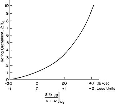
Figure 21.3 Degradations (increases) in pilot rating for tracking tasks associated with degree of pilot lead required. (FromMcRuer, AGARDograph 188, 1974)

model is found to be of high order, but with characteristics similar to the crossover model (Thompson and McRuer, 1988).

The linear optimal pilot model hasbeen used to advantage in the generation of pilot ratings (Hess, 1976; Anderson and Schmidt, 1987), the analysis of multiaxis problems (McRuer and Schmidt, 1990), and the stability of the pilot-airplane combination in maneuvers (Stengel and Broussard, 1978).

Frederick Lanchester

Airplane stability and control theory in the modern sense began with Frederick William Lanchester. Lanchester was not really a theoretician but a mechanical engineer who devoted most of his effort to the construction of very innovative motor cars. He performed aeronautical experiments with free-flying gliders. He speculated correctly on the vortex theory of lift and the nature of the vortex wake of a finite wing but was unable to give these ideas a useful mathematical form. His free-flying gliders were inherently stable and exhibited an undulating flight path, which he analyzed correctly in 1897. He misnamed the motion the “phugoid,” intending to call it the “flying” motion; actually he called it the “fleeing” motion, having forgotten that the Greek root already existed in the English word “fugitive.”

Lanchester published two books, Aerodynamics in 1907 and Aerodonetics in 1908, which expressed his views and the results of his experiments. He even talked with Wilbur Wright, evidently to no avail, because Wilbur had no understanding of inherent stability in flight, already demonstrated by Penaud, Langley, and Lanchester on a small scale.

Airstream Deviation Due to Inflow

A jet or rocket stream issuing from a nozzle acts like a hydrodynamic sink on the surrounding free-stream cold air flow. H. B. Squire and J. Trouncer (1944) produced beautiful isocline maps of the free-stream deviation angles around a jet (Figure 4.6). The sense of the deviation angles is for the surrounding free-stream flow to feed into the jet. Squire and Trouncer’s calculated deviation angles are parameterized in terms of the ratio of jet to free-stream velocities. The larger the velocity ratio, the larger is the deviation angle.

If airspeed is reduced from a trim value at a fixed throttle setting, the ratio of jet to free-stream velocity increases. This increases the free-stream deviation angles into the jet at any given location. In the common case in which the jet passes under the horizontal tail, this increases the effective downwash angle as the speed is reduced. This in turn provides a nose-up pitching moment at speeds below trim, a destabilizing effect. Forward neutral point shifts of as much as 10 percent of the wing mean chord are found for airplanes whose jet exhausts are forward of the horizontal tail. Conversely, only minor stability effects are measured for jet exhausts behind the horizontal tail.

Squire and Trouncer’s calculated stream deviation angles into a jet are for a jet stream at the same temperature as a free stream. A correction is needed to apply their data to the heated jets that come from actual jet or rocket engines. The equivalent cold jet velocity ratio is related to the actual jet velocity ratio by a function involving the ratio of the jet temperature to free-stream temperature.

Wing-Body Interference

The longitudinal, lateral, and directional stability of wings and bodies in combi­nation are the isolated characteristics plus effects that reflect modification of the flow by interference. In the longitudinal case, upwash ahead of the wing and downwash behind the wing change the body local angles of attack that enter into the Munk momentum theory calculations. Munk’s apparent mass theory for bodies was extended by Hans Multhopp (1941) to account for the nonconstant fuselage angle of attack due to the wing’s flow field. Gilruth and White (1941) used strip theory for this modification.

Stability and control designers have known for some time that whether an airplane has a high or a low wing influences static directional and lateral stabilities. There was an organized study of this at NACA starting in 1939 as a part of a broader attack on the factors influencing directional and lateral stability. The wing position part of the study was completed in 1941 by House and Wallace.

Distortion of the wing’s spanwise lift distribution and trailing vortex system due to sideslip has the following systematic effects:

Low wing airplanes: Static lateral stability is reduced by about 5 degrees of equivalent wing dihedral as compared with mid-wing airplanes. This rule of thumb has lasted to the present day. Static directional or weathervane stability is increased.

High wing airplanes: The reverse of the low wing case. Dihedral effect is increased by about 5 degrees, weathervane stability is decreased.

Cross-Flow Concept The cross-flow concept aids in understanding aerodynamic forces for an airplane in sideslip. The total velocity vector VEL of an airplane in sideslip can be resolved into a component U along the X or longitudinal body axis and a component V along the Y or lateral body axis. The U component gives rise to a symmetric flow, while the V component gives rise to a hypothetical flow at right angles, along the Y body axis. The component flows add together to make up the total streamline pattern of the airplane in sideslip.

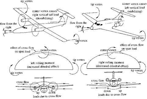
The V or cross-flow component is represented in Figure 6.2. This figure provides an explanation for the effects of high and low wing positions on stability. The effects are the result of the distortion of a wing’s span load distribution in sideslip. Undistorted wing span load distributions feature sharp gradients of load with spanwise distance at both wing tips.

Wing-Body Interference

Figure 6.2 Cross-flow explanation of wing vertical position effects on directional stability and di­hedral effect. Distortion of the wing span load in right sideslip creates a center vortex that gives destabilizing sidewash for a high wing and stabilizing sidewash for a low wing. The distorted span load gives increased dihedral effect for a high wing and decreased dihedral effect for a low wing.

Local shed vortex strength is proportional to this gradient, resulting in the familiar wing tip vortices. The flow of air from higher to lower pressure determines the sense of vortex rotation. Thus wing tip vortices rotate to create downflow, or downwash, inboard of the wing tip.

The center vortices shown in Figure 6.2 are the result of the local span load distortion due to wing-fuselage interference in sideslip. Center vortex rotations for low and high wing arrangements in sideslip are seen to be consistent with the observed stability changes noted above.

The Case of the Grumman/American AA-1B

The Grumman/American AA-1B Yankee, its Tr-2 trainer version, and the Tiger four-seat variant are clever, innovative personal airplane designs. Compared with most airplanes of the type, which are built as riveted metal structures, metal-to-metal bonding on these airplanes eliminates drag due to rivets and skin waviness and the points of stress concentration common to riveted structures. More than 2,000 AA-1B’s have been built, under several designations. Yet the AA-1B has compiled a sad record of crashes as a result of unrecoverable spins. The AA-1B has a flat spin mode that leads to a high-impact vertical crash with the fuselage level, a crash that has made paraplegics out of student pilots and their instructors.

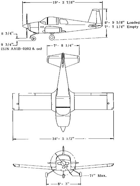
The airplane’s three-view diagram suggests that NACA spin recovery criteria were quite disregarded in the original design. The horizontal tail is mounted low on the fuselage, providing very little tail damping ratio, or TDR (Figure 9.7). By NACA correlation, this would promote a high angle of attack, or flat spin. Also, there appears to be virtually no unshielded rudder area, the NACA URVC factor.

The AA-1B’s poor spin and recovery characteristics are recognized in the 1975 version of the owner’s manual. In both the operating procedures and operating limitations sections

The Case of the Grumman/American AA-1B

Figure 9.7 Grumman-American AA-1B, known for unrecoverable flat spins. There is very little fuselage side area under the horizontal tail, needed for spin damping according to the NASA TDR criterion. There is also little unshielded rudder area above the horizontal tail. (From AA-1B Owner’s Manual)

the legend “SPINS ARE PROHIBITED” is displayed. This is followed by the recovery technique in the event of inadvertent spins, and the note:

If recovery controls are not briskly applied in the first turn, more than one additional turn will be required for recovery. For quick recovery, apply full anti-spin controls as the spin begins, before one turn is completed.

A later version of the owner’s manual has wording that reflects actual NASA flight-testing experience:

There is evidence that permitting the airplane to go beyond one turn without initiating proper recovery procedures can allow a spin mode to develop from which recovery is not possible.

To illustrate this point, the 1/15 December 1990 issue of Aviation Consumer reports that American Aviation test pilot Bob Hommel was forced to jump when a modified AA-1A failed to recover during a spin test. The airplane was said to have completed over 100 turns before crashing. There is no reason to think that the AA-1B airplane is unique in having recovery problems in spins that go beyond one turn. James S. Bowman, Jr., writes as follows:

I think it is important to mention that all normal category airplanes are tested for one-turn spins only and if taken beyond one turn, recovery may be slow, or there may be no recovery at all.