In fly-by-wire systems control surface servos are driven by electrical inputs from the pilot’s controls. Single-channel fly-by-wire has been in use for many years, generally through airplane automatic pilots. For example, both the Sperry A-12 and the Honeywell
|
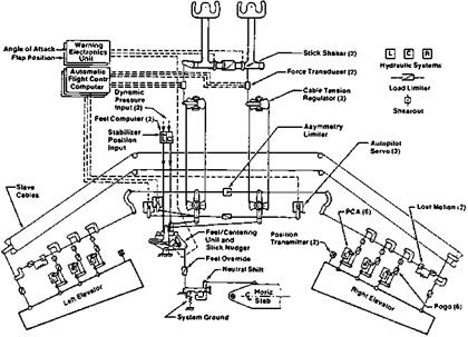
Figure 5.17 Schematic of the Boeing 767 elevator control system, possibly the last fly-by-cable or mechanical flightcontrol systemto be designedforaBoeing transport. Each elevatorhalfispoweredby three parallel hydromechanical servo actuators. Camoverrides (Pogos) and shearunits allow separation of jammed system components. (Reprinted with permission from SAE Paper No. 831488, © 1983, Society of Automotive Engineers, Inc.)
|
C-1 autopilots of the 1940s provided pilot flight control inputs through cockpit console controls. However, in modern usage, fly-by-wire is defined by multiple redundant channel electrical input systems and multiple control surface servos, usually with no or very limited mechanical (cable) backup.
According to Professor Bernard Etkin, a very early application of fly-by-wire technology was to the Avro Canada CF-105 Arrow, a supersonic delta-winged interceptor that first flew in 1958. A rudimentary fly-by-wire system, with a side-stick controller, was flown in 1954 in a NASA-modified Grumman F9F (Chambers, 2000). The NASA/Dryden digital fly-bywire F-8 program was another early development. Readers can consult Schmitt (1988) and Tomayko (2000) for the interesting history of airplane fly-by-wire.
The Boeing 767 is probably the last design from that company to retain pilot mechanical inputs to irreversible power control actuators, or fly-by-cable. The 767 elevator control schematic shows a high redundancy level, with three independent actuators on each elevator, each supplied by a different hydraulic system (Figure 5.17). Automatic pilot inputs to the system require separate actuators, since the primary surface servos do not accept electrical signals.
The Boeing 777 is that company’s first fly-by-wire (FBW) airplane, in which the primary surface servos accept electrical inputs from the pilot’s controls. With the Boeing 777, flyby-wire can be said to have come of age in having been adopted by the very conservative Boeing Company. Fly-by-wire had previously been operational on the Airbus A320, 330, and A340 airplanes
Figure 5.18 (Osder 1999) shows the redundancy level provided on the Boeing 777 control actuators. In this figure PFC refers to primary flight control computers, the ACE are actuator control electronic units, the AFDC are autopilot flight director Controls, the PSA are power
|
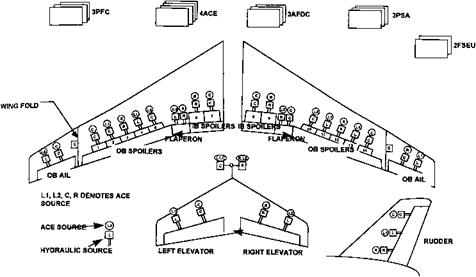
Figure 5.18 Redundancy level provided on the Boeing 777 Transport. PFC = primary flight computer, ACE = actuator control electronics, AFDC = autopilot flight director, PSA = conditioned power, FSEU = flap slatelectronics unit. (From Osder, 1999).
|
supplies, and the FSEU are secondary control units. Note the cross-linkages of the ACEs to the hydraulic power sources.
McLean (1999) gives interesting details on the 777 and A320 fly-by-wire systems:
[Boeing 777] …to prevent pilots exceeding bank angle boundaries, the roll force on the column increases as the bank angle nears 35 degrees. FBW enables more complex inter-axis coupling than the traditional rudder crossfeed for roll/yaw coordination which results in negligible sideslip even in extreme maneuvers… the yaw gust damper (which is independent and separate from the standard yaw damper on the aircraft)… senses any lateral gust and immediately applies rudder to alleviate loads on the vertical fin. The Boeing 777 has an FBW system which allows the longitudinal static margin to be relaxed – a 6 percent static margin is maintained… stall protection is provided by increasing column control forces gradually with increases in angle of attack. Pilots cannot trim out these forces as the aircraft nears stall speed or the angle of attack limit.
[Airbus 320].. . sidestick controllers are used. The pitch control law on that aircraft is basically a flight path rate command/flight path angle hold system and there is extensive provision of flight envelope protection… the bank angle is limited to 35 degrees
There is pitch coordination in turns. A speed control system maintains either VREF [a reference airspeed] or the speed which is obtained at engagement. There is no mechanical
backup___ Equipment has to be triplicated, or in some cases quadruplicated with automatic
“majority voters” and there is some provision for system reconfiguration.
The two cases illustrate an interesting difference in transport fly-by-wire design philosophy. Boeing 777 pilots are not restricted from applying load factors above the limit, except by a large increase in control forces. Wings could be bent in an emergency pullout. Airbus control logic prevents load factors beyond limit.
The McDonnell Douglas F/A-18 Hornet represents a move in the direction of completely integrated flight control actuators. Pilot inputs to the F/A-18’s all-moving horizontal tail or stabilator are made through two sets of dual solenoid-controlled valves, a true “fly-by-wire”
|
.MECHANICAL FEEDBACK UVPICAO
|
|
 |
|
|
|
|
|
|
|
 |
|
FAILSAFE SOIENOIO VALVE IDE-ENtRGlZEOl
|
|
 |
|
(PRESSURE T#F
TO CLOSE SWITCHI
|
|

INLET CHECK
RESTRICTOR
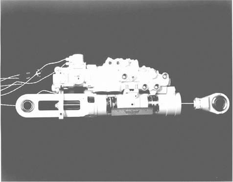
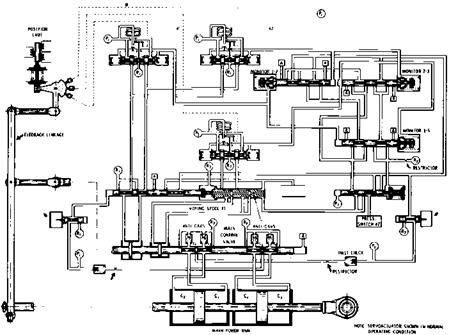
Figure 5.19 Photograph and schematic of the General Dynamics F-16 Integrated Servo Actuator (ISA) made by the National Waterlift Company. This actuator design is typical of an entirely fly-bywire flight control system. The actuator uses mechanical rate (main valve spool position) and position feedback, although electrical feedback has been tried. Internal hydromechanical failure detection and correction, using three independent servovalves, causes the piping complexity. (Reprinted with permission from SAE Paper No. 831483, @ 1983, Society of Automotive Engineers, Inc.)
system. A mechanical input from the pilot is applied only in the event of a series of electrical failures and one hydraulic system failure.
The General Dynamics F-16 is a completely fly-by-wire airplane, incorporating fully integrated servoactuators, known by their initials as ISAs. Each actuator is driven by three electrically controlled servo valves (Figure 5.19). There are no mechanical valve inputs at all from the pilot. Of course, the servo valves also accept signals from a digital flight control computer. The complexity seen in the ISA schematic is due to the failure detection and correction provisions. Only two of the three servo valves operate normally. A first failure of one of these valves shifts control automatically to the third servo valve. A first failure of the third servo valve locks the actuator on the sum of the first two.
The F-16 servoactuators also are used as primary surface actuators on the Grumman X – 29A research airplane. Integrated servoactuators of equivalent technology were developed by Moog, Inc., for the Israeli Lavi fighter airplane.
The Northrop/Lear/Moog design for the B-2 Stealth bomber’s flight controls represents another interesting fly-by-wire variant. On this quite large airplane part of the servo control electronics that normally resides in centralized flight control computers has been distributed close to the control surfaces. Digital flight control surface commands are sent by data bus to actuator remote terminals, which are located close to the control surfaces. The terminals contain digital processors for redundancy management and analog loop closure and compensation circuits for the actuators. Distributing the flight control servo actuator feedback functions in this manner saves a great deal of weight, as compared with using centralized flight control computers for this function (Schaefer, Inderhees, and Moynes, 1991).
Other modern fly-by-wire airplanesinclude the McDonnell DouglasC-17, the Lockheed- Martin F-117 and F-22, the NASA/Rockwell Space Shuttle orbiter, the Antonov An-124, the EF 2000 Eurofighter, the MRCA/Tornado, the Dassault Breguet Mirage 2000 and Rafale, the Saab JAS-39, and the Bell Boeing V-22.


