Category BASIC AERODYNAMICS

Moment Coefficient

Because the maximum camber ratio of a thin airfoil is small by definition, the moment expression for a cambered airfoil can be represented adequately by the expression derived for a symmetrical airfoil (i. e., flat plate). Then, referring to Fig. 5.21 and the development for a symmetrical airfoil:

c c

MLle = – J(PL – PU)(x)dx = – J(pVji)(x)dx.

0 0

Moment Coefficient Подпись: Jy (Ф)[1 - cos Ф]^ІП ф)dф. 0

Applying the transformation from linear to angular measure and writing this equation in coefficient form results in:

Moment Coefficient Moment Coefficient Подпись: (5.31)

Substituting for у (ф) = у (0) from Eq. 5.21 and integrating using basic trigonometric identities and integral tables results in:

The moment coefficient for a cambered airfoil is seen as depending on only three Fourier-series coefficients and as a function of the angle of attack and camber.

The Symmetrical Thin Airfoil

_L Г Y

2 n0(*- ^

Подпись: VjL Подпись: (5.7)

In this case, the mean camber line and the chord line coincide. Thus, when the thick­ness is stripped away, the airfoil is a flat plate and the vortex-sheet representation is along the chord so that the planar-boundary-condition approximation becomes exact. Furthermore, for the symmetric airfoil, dz / dx = 0, and Eq. (5.6) becomes:

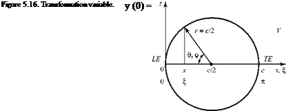
It is convenient to make a change of variable to perform the integration. Let:

c

Подпись: (5.8) = 2(1 – cos0),

where 0 is the new running variable. The fixed point in question, x, is denoted by:

Подпись: (5.9)x = 2(1 – cosФ).

This change of variable is equivalent to specifying chordwise location by angular rather than linear measure. Imagine a circle of radius c/2 centered at mid-chord (Fig. 5.16).

c

Подпись: 1 г у (0) sin 0d0 2n 0 (-cosф + cos0) Подпись: V~a. Подпись: (5.10)

At the limits of integration, x = 0 ^ 0 = 0 and x = c ^ 0 = n. Finally, d^ = — sin0d0 . Then, the defining equation for a symmetric airfoil, Eq. 5.7, may be written as follows:

The Symmetrical Thin Airfoil Подпись: (5.11)

This equation may be solved by integral-equation techniques that are beyond the scope of this text. The result is:

The claim that this is the solution may be verified by substituting Eq. 5.11 into the integrand of Eq. 5.10); namely: Evaluating the integral in Eq. 5.12b requires that we address the singular behavior of the integrand at 0 = ф (i. e., when the running variable is at the point in question, £ = x). This is done by using the “principal value” of the integral (see Appendix E in Abbott and Van Doenhoff (1959)):

where n may be 0, 1, 2, . . . depending on the form of the integrand. In the case of interest here, n = 0 and n = 1 in Eq. 5.12b. Thus, Eq. 5.12b becomes:

aV

—- [0 + n] = Va n –

and the solution, Eq. 5.11, was verified.

Подпись: Y (n) = lim 0->Я Подпись: 2Va(l + cos 0 sin 0 Подпись: 0, 0,

Notice also that if Eq. 5.11 is the solution, then it must exhibit the proper behavior at the trailing edge, 0 = n. At the trailing edge:

Подпись: lim 0— Подпись: 2Vjx(-sin 0) cos0 Подпись: = 0.

which is indeterminate. However, using L’ Hopital’s Rule (recall that the numerator and denominator are differentiated within the limit):

Thus, Y(n) = 0 and the Kutta condition is satisfied.

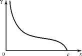
At the leading edge, 0 ^ 0 and Eq. 5.11 indicates that the vortex-sheet strength becomes infinite. This is allowable because the Kutta condition makes no demands on leading-edge behavior. The leading edge of even a thin airfoil is rounded, and the flat or curved plate representation of the airfoil simply breaks down at this single point. This is interpreted here as a limiting representation of what is called leading – edge suction, the low pressure (i. e., high velocity) caused by the flow rapidly accel­erating around the leading edge of an airfoil from the bottom to the top surface. The vortex-sheet strength then has the general characteristics depicted in Fig. 5.17. Having verified the solution, Eq. 5.11, we now can determine the expressions for the lift and moment coefficients for the symmetrical airfoil.

Figure 5.17. Vortex-sheet-strength distribution.
The Symmetrical Thin AirfoilThe lift coefficient is found by (1) appealing to the Kutta-Joukowski Theorem, and (2) finding the pressure distribution over the plate and then integrating. The fact that the two results are identical serves as further verification of the vortex theory of lift.

1. The total circulation around the airfoil is found by summing all of the contribu­tions due to the vortex elements—namely:

c П

r = J Y(£)d£ = C j у (0) sin Ш

0 2 0

after the change of variable. Substituting the solution, Eq. 5.11, into this inte­grand yields:

Подпись: (5.14)Г = caVrj (1 + cos0)d0 = canVr.

0

The Kutta-Joukowski Theorem then states that the lift per unit span is:

L’ = pVT = pVfcna

The Symmetrical Thin Airfoil Подпись: = 2na. Подпись: (5.15)

and the two-dimensional lift coefficient is:

The quantity unity in the denominator is a reminder that L’ is the lift per unit span.

2. The lift coefficient now is found by integrating the pressures acting on the sym­metrical thin airfoil (i. e., flat plate). These pressures always act perpendicular to the surface (Fig. 5.18).

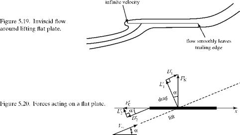
At first glance, Fig. 5.18 is puzzling. It indicates that the net pressure force on the plate acts in the z-direction; that is, it acts as a force normal to the chord. Then, this normal force apparently can be decomposed into two forces: one perpendicular to the freestream direction and the other parallel to the freestream direction. By defi­nition, the force perpendicular to the freestream direction is the lift force. Also by definition, the force component parallel to the freestream direction is the drag force. However, there can be no drag force in a two-dimensional, inviscid flow, as indicated in D’Alembert’s Paradox. There can be neither frictional nor pressure drag because no boundary layer is represented in the inviscid model.

The answer to this apparent contradiction is that there is another force acting on the plate—namely, a suction force at the leading edge acting in the chordwise (i. e., x-axis) direction. Recall that there is no boundary condition imposed at the leading edge, such as the Kutta condition at the trailing edge, and that this presents no practical problem because even thin airfoils have rounded leading edges with no anomalous velocity behavior. However, in the analytical model, in the limit of zero thickness, the inviscid flow has an infinite velocity as it accelerates around the sharp leading edge of the flat plate (Fig. 5.19). This infinite velocity produces an infinite negative pressure (i. e., suction) at the leading edge (according to the Ber­noulli Equation), and this infinite suction acts on a zero-thickness plate. In the limit, the product of the infinite suction per unit area acting on an infinitesimal plate area is a finite force in the chordwise upstream (i. e., thrust) direction. The forces acting on the flat plate then are as shown in Fig. 5.20, where F ‘N is the normal force per unit span and F’ C is the chordwise force per unit span. In the figure, each of these two forces is decomposed into lift and drag components.

From Figs. 5.18 and 5.20, it follows that:

c 1 T/2 1 T/2

FN = J(pL – Pu)dx and Pl~ po – 2pVL ; pu _ Po – 2pVu,

0

The Symmetrical Thin Airfoil

Подпись: F' = F N
The Symmetrical Thin Airfoil
Подпись: VU + VL
Подпись:  dx.

where Bernoulli’s Equation was used. Because the stagnation pressure, p0, is con­stant throughout the flow, we find that:

The Symmetrical Thin Airfoil Подпись: = V^cos a.

As previously noted, (Vu – VL) = y, so the first term in the integrand is the local vortex-sheet strength. Also, by applying the exact Joukowski-transformation method discussed in the last section to the special case of flow around a flat-plate airfoil, it may be shown that:

Thus,

c

FN= pV^cosa J jdx =pV^r cos a. (5.16a)

0

Notice that Eq. 5.16 does not state that exactly F’N = рУ^Г, nor should it because it is an expression for the normal force, not the lift force, per unit span.

Rather than pondering how to evaluate the product of an infinite pressure and an infinitesimal area, a simpler approach is to argue that in this two-dimensional, inviscid flow, the drag force on the plate must be zero. That is, D – D’2 = 0, where a positive drag force is in the streamwise direction, so that D’ 2 = DFrom Eq. 5.16a and Fig. 5.20:

D[ = FN sin a = (рУмГ cos a) sin a.

D’

Подпись: FFurthermore, from geometry, —L = cos a. Solving for F’ C and substituting for D 2 = D’ 1

Подпись: (5.16b), Г cos a)sin a,

FC =^-^—————- = (pV Г)sin a.

C cos a ”

Finally, we recognize that the total lift on the plate is given by L’ = L’ 1 + L’2, so that:

L’ = FN cos a + FC sin a.

Substituting from Eq. 5.16:

L’ = pVM(cos2 a + sin2 a) = pV^r,

which agrees with the Kutta-Joukowski Theorem result, and the vortex theory of lift is verified. Finally, using Eq. 5.15, Q = 2na.

Thus, according to thin-airfoil theory, for a symmetrical airfoil, the airfoil lift coefficient is given by:

The Symmetrical Thin Airfoil Подпись: (5.17b)

and the corresponding lift-curve slope is:

These equations state that the lift coefficient varies linearly with the angle of attack. It is shown later that this prediction is in excellent agreement with experimental data at moderate angles of attack before flow-separation effects begin to dominate and stall is approached. This can be seen for the special case illustrated in Fig. 5.3: The linear behavior applies to the unflapped NACA 4415 airfoil in the angle-of-attack range -10 ° < a < 10 °.

Notice in Eq. 5.17 that because the lift coefficient is dimensionless, the angle of attack must be in radians, which also is a dimensionless quantity. Eq. 5.17a is some­times written as Cg = m0a, where m0 is the lift-curve slope in radians. The coefficient, m0, may be assigned its theoretical value, m0 = 2n, or it may be determined from experimental, two-dimensional test results. Alternately, Eq. 5.17a may be written as Q = a0a, where a0 is the lift-curve slope per degree (i. e., thin-airfoil-theory result:

0. 11 per degree) and the angle of attack then is written in degrees.

The airfoil pitching moment may be found about any point on the chord line and then transferred to any other point. For convenience, the pitching moment per unit, span, M’, is taken about the airfoil leading edge as shown is Fig. 5.21. The moment may be evaluated either by summing up the contribution due to each element of the vortex sheet or by evaluating the moment due to the pressure distribution on the airfoil (i. e., plate). The latter approach is more physical and is used here.

Let a clockwise moment about the leading edge be positive. Then, the moment about the leading edge due to a pressure difference over an interval dx, at any dis­tance x from the leading edge is obtained by integration—namely:

c

MLE = – J (PL – Pu)xdx.

0

The minus sign is introduced because if PL > PU, the moment contribution is coun­terclockwise and therefore must be negative.

In the development of Eq. 5.16a, it is shown that (PL – PU = pyE^ cos a. Because the angle of attack is small, this can be approximated by:

(Pl – Pu) = PY

and the small angle approximation is used wherever needed. Then, we use Eq. 5.11 for the vortex-sheet strength, y, and the transformation to angular measure from

z

Figure 5.21. Pitching moment about

Pu

the leading edge.

+

У ,

dx ‘

x

Pl

Eq. 5.8. Writing the variable of integration in the moment definition as E rather than x to emphasize that it is a dummy integration variable:

Notice that for the moment coefficient to be dimensionless, the definition must con­tain a length squared in the denominator because the numerator now contains a lever-arm length. Also, notice that at positive angles of attack, the airfoil pitching moment is negative or clockwise; hence, it is a nose-down pitching moment, or a so – called restoring moment.

Two other properties of the symmetrical airfoil can be deduced from Eq. 5.18. Recall from Section 5.1 that the center of pressure is the point on the airfoil about which the moment is zero. We multiply both sides of Eq. 5.18 by (q^c2), which gives:

ML e = – 4 L’.

This result states that lift is the only contributor to moment and that the integrated lift force can be interpreted as a point force with its line of action at the quarter – chord point, as shown in Fig. 5.22. Thus, at the point c/4, the lever arm of the lift force is zero and the moment about that point is zero. It follows that the quarter-chord point of the symmetrical airfoil is the center of pressure.

Подпись: Figure 5.22. Location of resultant lift force on symmetrical airfoil.

Also recall from Section 5.1 that the aerodynamic center is the point on the airfoil where the moment is independent of the angle of attack. From Eq. 5.17a, the lift varies with the angle of attack. Because lift is the only contributor to moment, then the only point on the airfoil where the moment is independent of the angle of attack is the point where the lift-force lever arm is of zero length. Again, this is the

quarter-chord point. At this point, the pitching moment is not only independent of the angle of attack, it also is zero. Thus, for a symmetrical thin airfoil, both the center of pressure and the aerodynamic center are located at the quarter-chord point.

The Cambered Thin Airfoil

± r y(S№ V 2(*- k) “

Подпись: a- Подпись: dz dx Подпись: (5.6)

The cambered-thin-airfoil problem requires that the vortex-sheet strength be found from Eq. 5.6, given the angle of attack and the equation of the mean camber line. Thus, the following integral equation must be solved for y(x):

As in the symmetrical-airfoil case, it is more convenient to cast this equation in angular measure, as in deriving Eq. 5.10. Thus, Eq. 5.6 becomes:

Подпись:_L Г Y(в)sin0d0 = V L Jdz

2^0 (-cos ф + cos 0) v dx,

where 0 is an integration variable, ф designates the fixed point in question, and dz / dx is the slope of the mean camber line evaluated at the point in question. The solution for the vortex-sheet strength, y (0), in Eq. 5.19 is subject to the Kutta con­dition, y (n) = 0.

Подпись: Run Program FOURIER to review features of the Fourier series.

A solution to Eq. 5.19 is sought by applying a Fourier-series approach. We realize that because the cambered airfoil is represented as an airfoil of zero thickness (i. e., a curved flat plate), the vortex-sheet strength for the cambered airfoil must have the same general character as the distribution shown in Fig. 5.17 for a symmetrical airfoil; namely: Y (x) must be zero at the trailing edge and infinite at the leading edge. Now, recall from engineering mathematics that any curve or function may be represented over an interval by an infinite series comprising both sine and cosine terms—that is, a Fourier series.

For the current problem, the interval is from the leading edge (0 = 0) to the trailing edge (0 = n). In this problem, the cosine terms in the Fourier series are omitted because they would violate the Kutta condition—that is, the cosine terms would make a nonzero contribution to the source strength at the trailing edge, 0 = n. Thus, we represent the vortex-sheet distribution by the Fourier sine series as follows:

Y(0) =X Aisin n0. (5.20)

n=0

Now, the flow velocity and the vortex-sheet strength must be infinite at the leading edge of the cambered airfoil as in the symmetrical airfoil. To ensure the proper behavior at the leading edge, the first term of the series in Eq. 5.20, (n = 0), is written as a “flat-plate” term given by the symmetrical airfoil solution in Eq. 5.11. Some
generality is retained by writing the coefficient A0 in place of a. Then, the solution to Eq. 5.19 is represented by the Fourier series as follows:

Подпись: (5.21)Y(9) = 2 V a/1 + c°s 9) + 2 V У An sin и0. J sin9 “ПГі "

The coefficients An in the terms of the series n > 1 appearing in Eq. 5.20 were replaced by 2V“An in Eq. 5.21 to make a common multiplier (2V“ appear in all of the terms in Eq. 5.21. The constant value (2V“ simply is absorbed in the definition of An in the summation part of Eq. 5.21.

Of course, Eq. 5.21 is a solution only if there is a mechanism by which to solve for the coefficients of the series. This mechanism is supplied by imposing the boundary condition that the mean camber line must be a streamline. When the solution is completed, it should contain the symmetrical airfoil as a special case—namely, that A0 must equal a and all of the other An’s must be zero.

Substituting Eq. 5.21 into Eq. 5.19 yields:

Подпись: (5.22)1 П ATl + cos9)d9 1 A, sinn9sm9d9 (dz]

— I—————- + — І У —————– = a- —

п0 cos9-созф п0n=1 cos9-cosф ^dx,

The first term can be integrated directly by using the “principal value” as given by Eq. 5.13. The second term can be written in a form suitable for integration by appli­cation of the principal value in Eq. 5.13 if the numerator is written in terms of cosines by using the trigonometric identity:

sin n9sin 9 = 1 / 2[cos(n -1)0 – cos(n+1)9].

Substituting and integrating Eq. 5.22 leads to:

1

The Symmetrical Thin Airfoil

A0 + —{ A1(0) + A(n) +

The student should verify this result. Thus, on integrating, Eq. 5.22 can be written as:

Подпись:= a – A0 + У An тоs пф. (5.23)

n=1

Eq. 5.23 provides the mechanism for evaluating the An’s. The equation must hold at any chordwise station, x, at which station the left side is known and the angle ф is determined by the transformation x = (c/2)(1-cos ф). Notice that Eq. 5.23 also could be written in terms of 9 as ф because both angles correspond to “a chordwise station.” The two angles must be distinguished carefully only when they both appear together in an integrand.

The An’s in Eq. 5.23 are solved in two steps, using standard Fourier-series tech­niques, as follows:

1.

The Symmetrical Thin Airfoil

Solve for A0: Integrate Eq. 5.23 over the interval (0 – n); namely:

because over this interval:

П

J (A cos яф^ф = 0

0

for all n. Rearranging:

A =a– Jdzdф. (5.24)

0 n 0 dx

In this equation, the camber-line slope can be expressed as a function of the angle ф through the change of variable expression (see Example 5.1).

2. Solve for the remaining An’s. Multiply both sides of Eq. 5.23 by cos тф, where m is a dummy counter, and again integrate over the interval:

J —z cos mdФ = J (a – A)) ros mфdф + J ^ (An cos пф) cos mфdф = L^ +12.

0 dx 0 0n=1

П

From calculus, I1 = 0 for all values of m, whereas I2=0 when n Ф m and I2= —An

when n = m. 2

Using these facts and rearranging:

An = — f —z (cos пф^ф (n > 1). (5.25)

n п 0 dx

The vortex-sheet-strength distribution for the cambered thin airfoil now is known because Eqs. 5.24 and Eq. 5.25 provide the mechanism for evaluating the coefficients in the Fourier-series expression for у(0) = у(ф) in Eq. 5.21. Notice that the vortex – sheet strength depends on the local slope of the mean camber line because the slope appears in both coefficient equations. Also, note that for a symmetrical airfoil, A0 = a, and all of the other An’s are zero so that Eq. 5.21 reduces to the prior result for the symmetrical airfoil in this special case, as expected.

If the chordwise pressure distribution on the airfoil is required, all of the An’s must be found. Evaluating the aerodynamic coefficients is less demanding and the expressions for these coefficients are now determined.

Lift Coefficient

We recall that:

Подпись: L' = рУГ = pUj Y (Ж = pVj 2 Y (0) sin 0d0. 0 02 c П

Then, we substitute for у (9) the Fourier-series expression, Eq. 5.21, so that:

П П m

Подпись: cПодпись: L' = pVMі A. a + cos 9)d9 + IX An sm n9 sin 9d9 I.

0 0 n=1 _

These two integrals may be evaluated using basic trigonometric identities and inte­gral tables. The result is as follows:

Q = 1Тс = П(1 A^ + A1)- (5-26)

Подпись: a + — і4^(cos9- 1)d9 . n 0 dx Подпись: 2n(a + p), Подпись: (5.27)

Notice that the value of the lift coefficient depends on both the angle of attack and the camber of the airfoil and that only two Fourier coefficients need to be evaluated. Substituting for A0 and A1, Eq. 5.26 may be written as:

where в is an angle (in radians) whose magnitude (a constant for a given problem) only depends on the camber of the airfoil, a geometric property of the airfoil shape. From Eq. 5.27, the following facts emerge:

1. The lift-curve slope for an arbitrary thin airfoil is:

dC„

—1 = 2 n, (5.28)

da

which is the same expression as for a symmetrical airfoil.

2.

The Symmetrical Thin Airfoil Подпись: - і ^ (cos 9- 1)d9. n 0 dx Подпись: (5.29)

When the geometric angle of attack has the value a = – p, the lift coefficient (and the lift) is zero. This special angle of attack only depends on the character of the airfoil camber and is called the angle of zero lift, aLo. Setting Q = 0 in Eq. 5.27, the magnitude of this angle (in radians) is given by:

The angle of zero lift is always negative for a positive-camber airfoil.

3.

Подпись: a-a T L0 Подпись: = 2 naa Подпись: (5.30)

A new angle of attack, the absolute angle of attack aa, now may be defined from Eq. 5.27 with p set equal to – aL0. Thus,

Examine Fig. 5.23. If an airfoil has positive camber, then when the geometric angle of attack, a, is zero and the chord line is coincident with the flow direction, the lift coefficient is greater than zero. It is necessary to use a negative geometric angle of attack when the zero lift line (ZLL) is aligned with the flow to make the lift coefficient zero. The angle between the chord line and the ZLL is the angle of zero lift, a quantity that usually carries a negative sign. The absolute angle of attack is the angle between the oncoming flow and the ZLL. Notice also that the angle of zero lift is zero for a symmetrical airfoil.

Figure 5.23. Absolute angle of attack.

Vortex-Sheet Representation of a Thin Airfoil

An analytical solution for the vortex-sheet strength is not possible for an airfoil of arbitrary thickness ratio. Full numerical solutions were developed, as discussed in Section 5.7. However, an analytical solution can be constructed if the vortex-sheet model is applied to thin airfoils. If an airfoil is thin (i. e., 10 to 12 percent thickness ratio or less), then the vortex sheets on the airfoil upper and lower surfaces are close to the mean camber line. This fact can be approximated by distributing the vortex sheet along the airfoil mean camber line. This entails stripping off and discarding the symmetrical thickness distribution above and below the mean camber line, leaving only the mean camber line to represent the airfoil as shown in Fig. 5.12.

This approach provides results that are in good agreement with experiments for thin airfoils. The exact solution for a Joukowski airfoil discussed previously showed that the influence of thickness on lift and moment coefficient is minor if the thick­ness ratio is small. It is appealing to replace the mean camber line with a vortex sheet, because there is a jump in velocity across the vortex sheet as there would be across a mean camber line representing the airfoil because the mean camber line then is a streamline. Thin-airfoil theory represents a symmetrical airfoil as a flat plate and a cambered airfoil as a curved plate.

Again, the vortex-sheet strength as a function of chordwise distance is found by imposing the Kutta condition as well as the condition that the mean camber line must be a streamline (i. e., no flow component normal to the camber line). The circu­lation and the lift per unit span follow.

The uniqueness of the circulation about the airfoil as a function of angle of attack is a result of the Kutta condition. Recall from Section 4.9 that for a finite trailing-edge angle, the Kutta condition demands that the trailing edge be a stagna­tion point; whereas for a cusped trailing edge, the condition demands that the flow exiting the trailing edge at the upper and lower surfaces has the same velocity. At the trailing edge of the camber line, let the velocity be V. Thus, at the trailing edge (i. e., finite angle), Vy = VL = 0 or (cusp) Vy = VL. Recalling that the local sheet strength was shown to be equal to the local jump in velocity across the sheet, у = (Vy – VL), it follows that in either case, y(TE) = 0. The other condition on у(s) is that the mean camber line must be a streamline.

Подпись: Figure 5.12. Mean camber line represented as a vortex sheet. Vortex-Sheet Representation of a Thin Airfoil

Consider a thin airfoil at angle of attack and represented by a vortex sheet dis­tributed along the mean camber line. Place the airfoil in a body-axis coordinate

system (Fig. 5.12) with the x-axis aligned with the chord line. The equation of the mean camber line, z(x), is known. The vortex-sheet strength, у (s), is determined and then used to find the pressure distribution, Cp(x); the lift coefficient, Q ; and the pitching moment coefficient, Cm.

If the mean camber line is to be a streamline, there can be no flow through the vortex sheet. This means that at every point along the vortex sheet, the velocity component, V(s), is perpendicular to the mean camber line (see Fig. 5.13). V(s) is induced by all other elements of the vortex sheet. It must be equal and opposite to the normal component of the freestream velocity, V*n, which is normal to the mean camber line at that point. Thus, V(s) + V*n = 0 at every point along the mean camber line, as shown in Fig. 5.13.

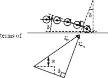
Formulate V*n by expressing V*n in terms of the slope of the mean camber line at any point. The slope of the mean camber line is given by dz/ dx, which is a known. Then, the angle 5 = tan-1(-dz / dx), where the minus sign is added to keep the sense of the angle correct. That is, when the camber-line slope, dz/dx, is negative, then (a + 5) should be additive, as shown in Fig. 5.14. Near the front of the airfoil, when the mean camber-line slope is positive, the opposite is true.

V* n= V* sin(a + 5) = V^sin

Подпись: / a + tan-1 . V
Подпись: dz'] dx J

From Fig. 5.14:

V = V

* n *

Подпись: a-& . dx,
Подпись: (5.4)

For a thin airfoil at a moderate angle of attack, this may be approximated as:

It remains to derive an expression for V(s) to complete the boundary-condition statement.

Finding the expression for V(s) is not particularly straightforward because V(s) is the resultant velocity induced at a point on the curved sheet by all of the other elements of the sheet. Thus, referring to Fig. 5.9(b), the Point P now is on the sheet

Vortex-Sheet Representation of a Thin AirfoilVortex-Sheet Representation of a Thin AirfoilFigure 5.13. The camber-line boundary condition.
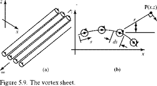
Figure 5.14. The streamline boundary condition in camber-line slope
but the line r from each element of sheet ds to the Point P has a different orientation in the general case of a curved sheet. In addition to determining each slant distance, r, this means that each dV induced by y ds at Point P is at a different angle. The complexity is overcome again by taking advantage of the thin-airfoil geometry. We realize that if the thickness ratio is small, then the maximum camber ratio must be even smaller (i. e., a few percentage points), and the mean camber line is not far from the chord line—that is, the x-axis. Thus, only a small error results if the vortex sheet is placed along the chord line and the induced velocity is evaluated there. We assume in effect, that s ~ x and V(s) ~ V(x). This approximation is termed satisfying the boundary condition in the plane, a method that is often used in similar geometrical situations. Remember that even though the induced velocity is evaluated along the x-axis, the theory still insists that the mean camber line be a streamline. That is, the sheet strength is evaluated by demanding that the mean camber line be a streamline, not that the chord line be a streamline. This approximation greatly simplifies the geometry that enters the induced velocity calculation, as indicated in Fig. 5.15.

Recalling from the previous discussion of the vortex sheet that the induced velocity dV = – y ds/2nr, it follows from Fig. 5.15 that:

here the integration sums all of the dV at an arbitrary (but fixed) point, x, induced at that point by the element of the vortex sheet at the location S. Here, S is a running variable that disappears on integration. Notice that the integrand is singular (i. e., blows up) at x = S. (This is addressed later.) Remember that even though this V(x) is perpendicular to the chord line, it is treated as if it were perpendicular to the mean camber line. Thus, in the boundary-condition expression, V(x) is set equal and oppo­site to Vron at the mean camber line—namely, V^n + V(x) = 0.

_L Г Ж№ = V 2n0(*“S) “

Подпись: a- Подпись: dz dx Подпись: (5.6)

Assembling Eqs. 5.4 and 5.5, the boundary condition requires that at any arbi­trary (but fixed) chordwise station:

Подпись: Figure 5.15. The chord-line approximation. Подпись: y

Eq. 5.6 is the basic equation of thin-airfoil theory. The right side is known because the angle of attack must be given and the mean camber line is specified for a given airfoil so that dz/ dx can be found. Eq. 5.6 represents an integral equation for the unknown y (x) and must be solved subject to the Kutta condition that y(c) = 0, as described in Chapter 4.

The symmetric thin airfoil and the airfoil with arbitrary camber are examined in the next two sections. The appeal of thin-airfoil theory is that it provides a com­pletely analytical solution; the disadvantage is that it applies only to thin airfoils. Applying the results to airfoils thicker than about 12 percent thickness ratio leads to increasingly larger errors when compared to experimental data.

Vortex-Sheet Representation of an Airfoil

An airfoil may be represented in an inviscid flow by wrapping a vortex sheet around its surface, as depicted in Fig. 5.11. This vortex sheet is of a variable strength, y ds. The strength can be found by applying the boundary condition that there is no flow through the solid surface of the airfoil. The boundary condition at infinity already is satisfied by the vortex-sheet property that at a large distance from a vortex, the induced velocity goes to zero lim (l/r) = 0. If the airfoil is lifting, the Kutta condition

r——^

also must be imposed.

Once the variable-sheet strength, y (s), is found, then:

Г = Х yAs — J Yds (5.3)

and the circulation around the airfoil can be determined. The value of the lift per unit span, L’ = pV^r, follows immediately from the Kutta-Joukowski theorem.

Подпись: Figure 5.11. Vortex sheet wrapped around an arbitrary airfoil. Vortex-Sheet Representation of an Airfoil

This representation of an airfoil by a vortex sheet (i. e., a collection of singu­larities, each of which is a solution to the linear Laplace’s Equation) is physically appealing as well as an application of the superposition principle for inviscid flows. Recall that in a real (viscous) flow, there is a thin boundary layer on the surface of

the airfoil, which is a region of high vorticity. The vorticity of the vortex sheet at the surface of the inviscid-flow model may be thought of as generated there by the boundary layer that would be present in the actual flow field.

The Vortex Sheet

The concept of the vortex sheet is central to thin-airfoil theory. A vortex sheet is a collection of vortex filaments, or threads, placed side by side. Each filament is

infinitesimal in strength and extends to ± infinity in a direction perpendicular to the x-z plane that contains the two-dimensional airfoil (Fig. 5.9(a)). The vortex filaments appear in cross section in the x-z plane as a series of point vortices (Fig. 5.9(b)). Notice that these coordinate axes depart from the simple (x, y) coordinates used in Chapter 4, which anticipates extension of the theory to the three-dimensional wing problem, as suggested in Fig. 5.1(a).

Recall that the velocity field associated with a single two-dimensional point vortex is everywhere perpendicular to a radius taken from the vortex as center. Thus, an isolated vortex may be thought of as inducing at a point of a velocity component that is at right angles to a line joining the center of the vortex to that point. The word inducing is emphasized because it is only a conceptual aid. The vortex does not cause a velocity; rather, a real vortical flow configures itself physically such that there is a viscous-dominated center and an associated velocity field with circular streamlines.

Referring to Fig. 5.9(b), let у = у(s) represent the strength of the vortex sheet per unit length along s. Thus, the strength of an infinitesimal segment of the sheet is the strength per unit length multiplied by the lengths—namely, уds. The vortex filaments contained within this small segment are combined and treated as a point vortex. These point vortices are assumed to rotate in a clockwise sense, as shown in Fig. 5.9. Recall from the definition of circulation, Eq. 4.8, and from Section 4.6 regarding a point vortex that for a vortex of finite strength with a clockwise sense, the vortex strength, Г, is positive and then

Г

Ue=- 2 nr

is negative. The notation for polar coordinates (Fig. 5.9(a)) thus indicates that the induced velocity ue is also in a clockwise sense. It follows that the velocity, dy, induced by a vortex filament is clockwise, as shown in Fig. 5.9(b), and that

Подпись: dy = -

The Vortex Sheet

yds 2nr ’

where dy is the differential velocity induced by a small segment of the vortex sheet.

Now, we consider a line integral taken around a length ds of vortex sheet. By definition, Eq. 4.8:

Г = – ф v • ds

The Vortex Sheet
Подпись: Figure 5.10. Circulation around a vortex-sheet element.

and integrating counterclockwise from Point A in Fig. 5.10:

dT = —(—uUds – v2dn + uLds + v dn),

where all of the velocity components around the path are assumed to be in the positive-coordinate directions. Letting dn — 0, this reduces to d Г = (uu – uL)ds.

Now, the strength of the segment of the vortex sheet contained within the closed path is y ds. Thus,

dГ = yds = (uU – uL)ds (5.2)

and y = (uu – uL). This result states that the local jump in tangential velocity across the vortex sheet at any point is precisely equal to the local sheet strength.

Distribution of Singularities on the Surface of a Body

A distribution of vortex singularities is used to represent a thin airfoil in the devel­opment of an analytical thin-airfoil solution. A distribution of vortex singulari­ties also is used in the treatment of three-dimensional lifting wings in Chapter 6. Distributions of other types of singularities are useful for certain applications, which now are introduced. For convenience, a distribution of singularities running from Point 1 to Point 2 along a Cartesian coordinate axis is considered for simplicity. In this interval, 1-2, there is an infinite number of singularities of infinitesimal strength; such a distribution is called a vortex sheet.

It is demonstrated in Chapter 4 that there is a jump in tangential velocity across a vortex sheet—that is, Am ф 0. As a result, the circulation, Г, around the sheet between x1 and x2 (Fig. 5.6) is nonzero.

It follows that a vortex sheet is a useful representation for a lifting body. The vortex is the singularity chosen in this chapter to analyze the behavior of two­dimensional airfoils and in later chapters for three-dimensional wings and bodies of revolution at angle of attack.

A distribution of sources (and sinks) is useful for flows that are symmetrical about an axis as depicted in Fig. 5.7. This type of distribution of singularities is used to treat bodies of revolution at zero angle of attack in Chapter 7.

Across the source sheet, u is continuous; however, there is a jump in w across the x-axis. Thus, the source sheet splits the streamlines and represents body thickness (recall the superposition of sources and sinks described in Chapter 4). The circu­lation around the source sheet is zero so that it is not useful for representing a lifting body. However, the source singularity may be used in conjunction with a vortex distribution to represent the thickness effect on a lifting body with finite thickness.

A doublet distribution also may be used to represent a lifting body. This state­ment must be considered carefully because a doublet was superposed with a uni­form stream in Chapter 4 to represent the flow around a nonlifting cylinder and a vortex singularity was added to produce asymmetric flow and lift. The distinction is that the doublet used to generate the flow around the cylinder was developed by placing the source-sink pair along the x-axis (i. e., streamwise direction) and then considering the limiting case with the two singularities meeting at the origin. The resulting doublet then was said to have its axis in the x-direction.

z, w >

Figure 5.6. Vortex-singularity distribution.

Now consider a source-sink pair located on the z-axis. Let the source be at the origin of the coordinate system and the sink be located on the positive z-axis, as shown in Fig. 5.8(a). This represents the same source-sink pair in Chapter 4 rotated clock­wise by 90 degrees. The streamlines are as shown. Now, we generate a doublet at the origin of the coordinates by letting h ^ 0 while keeping the product (Ah) a constant, where Л is the strength of the source-sink pair (Fig. 5.8(b)). We focus our attention on the flow direction at the origin and let the doublet at the origin represent one of a series of doublets of infinitesimal and variable strength distributed along the x-axis (but with the doublet axes in the z-direction), as shown in Fig. 5.8(c). Notice that the resulting doublet-sheet flow in the z-direction is into the top of the sheet and out of the bottom. Also note that this is not the same behavior found in the source sheet.

Detailed analysis (see Karamcheti, 1980) shows that there is no jump in w across the sheet. However, there is a jump in the velocity potential across the sheet and, hence, a jump in the u component of velocity across the sheet. This means that the circulation around the doublet sheet is nonzero. It follows that a two – or three-dimen­sional lifting body in a freestream can be represented by superposing a uniform flow and a distribution of doublet singularities on the surface of the body with the axes of the doublets in the z-direction. Physically, the doublet sheet may be thought of as imparting a downward momentum to the oncoming flow similar to a vortex sheet. This change in z-momentum generates a net lift force on the sheet and, therefore, on the body it represents.

Thus, flows involving lifting bodies may be modeled using either a vortex or a doublet distribution. In fact, on analysis, the local vortex-sheet strength per unit length, у (x), can be identified with the derivative of the doublet-strength distribution per unit length, dX/dx. In this textbook, the vortex-sheet distribution is used to rep­resent a lifting body rather than the doublet distribution because the interaction of the vortex and the flow is physically more apparent. The concept of lift introduced in Chapter 4 by means of a cylinder with circulation induced by a bound vortex then can be adapted readily to the study of airfoils.

Thin-Airfoil Theory

Catalogs of experimental airfoil data can be useful in airplane design. It is diffi­cult, however, to understand the physical behavior of airfoils and the relationships between airfoil aerodynamic performance and airfoil geometry simply by studying such data. There clearly is a need for an analytical method that allows the straight­forward prediction of airfoil behavior with satisfactory accuracy. Such a theory would allow the role of the airfoil shape parameters to be studied. For example, for a given maximum camber, is it better to place it near the leading or trailing edge of an airfoil to achieve the largest increase in lift coefficient compared to a symmetrical airfoil at the same angle of attack? The answers to this and related questions are derived readily from thin-airfoil theory.

Thin-airfoil theory is an approximate inviscid-flow theory that relies on an assumption of small thickness ratio (i. e., 10 to 12 percent or less) at moderate angle of attack (i. e., several degrees or less). Within this framework, the theory adequately predicts lift and moment for arbitrary thin airfoils. It does not yield information on drag because the D’Alembert’s Paradox interferes, which is a consequence of neglecting viscous-flow effects in constructing a simple theory.

NACA Six-Digit Airfoils

Six-digit airfoils were designed in the early 1940s with the objective of encouraging a longer run of laminar-boundary-layer flow along the surface to reduce the skin – friction drag. As described in detail herein, early transition from a smooth laminar flow to a turbulent flow leads to increased drag. In this airfoil configuration, the mean camber line and the thickness distribution are designed to generate a specific pressure distribution at a certain value of lift coefficient. These sections were the first to reflect the importance of delaying boundary-layer transition on the airfoil surface. The value of this design approach was demonstrated in the highly successful North American P-51 fighter of World War II fame; the high speed and impressive range were directly attributable to such drag-reducing design features.

For any NACA xxxxxx section:

First integer: identifies series (i. e., 6)

Second integer: chordwise location of minimum pressure in tenths of a chord for a basic symmetrical thickness distribution at zero lift

Third integer: range of Q (tenths) above and below the design-lift coefficient for which favorable pressure gradients exist on both airfoil surfaces Fourth integer: design-lift coefficient in tenths (reflects the amount of camber) Fifth and Sixth integers together: thickness ratio of section, percent chord

Thus, the NACA 64,3-212 airfoil is a six-series section with minimum pressure at 40 percent chord, a favorable pressure gradient for a range in lift coefficient of 0.3 above and below design, a design-lift coefficient of 0.2, and a thickness ratio of 12 percent.

There are variations on many of these airfoil shapes, and the nomenclature becomes more complicated. For example, the letter A appearing in the six-series designation means that the contour was altered near the trailing edge. Abbott and Van Doenhoff (1959) is a useful collection of results for NACA airfoils and also provides details of the airfoil-numbering system. The Riegels (1961) book is a com­prehensive catalog of airfoils developed at NACA and elsewhere, as well as a review of airfoil theory.

It often is useful to have a computer program that produces the coordinates of the NACA series. Program NACAFOIL is provided with the software package accompanying this text for that purpose. This program generates airfoil coordinates for the NACA four – and five-digit-series airfoils and stores them in a user-defined text file. This file is readable by other programs in the software package that can use airfoil data.

NACA Four-Digit Airfoils

This series has one basic thickness form, with the maximum thickness at 30 percent chord. Camber lines were chosen so that the maximum camber occurred from 20 to 70 percent of chord. For any NACA xxxx section:

First integer: maximum value of the mean camber line, percent chord Second integer: distance from the leading edge to point of maximum camber, tenths of a chord

Third and Fourth integers: thickness of airfoil, percent chord

Thus, the NACA 4415 airfoil section shown in Fig. 5.3(b) has a maximum camber of 4 percent chord located at 40 percent chord with a thickness ratio of 15 percent.

NACA Five-Digit Airfoils

Five-digit airfoils were designed in the mid-1930s to improve the pitching-moment characteristics of four-digit airfoils. Accordingly, they have the maximum camber farther forward than the four-digit series. Both the four- and five-digit series have the same basic thickness form (i. e., maximum thickness at 30 percent chord) as the four-digit sections.

For any NACA xxxxx section:

First integer: the section-lift coefficient in tenths is 1.5 times the first integer; this first integer is indicative of the amount of camber

Second and Third integers together: twice the value of the maximum camber, percent chord

Fourth and Fifthe integers together: thickness ratio, percent chord

Thus, the NACA 23012 section has a design lift coefficient of 0.3, a camber ratio of 15 percent, and a thickness ratio of 12 percent. The design-lift coefficient is defined as the theoretical value of the section-lift coefficient at an angle of attack such that the oncoming flow is tangent to the mean camber line at the leading edge.

The NACA Series of Airfoils

Beginning circa 1930, it was realized that there was a need to put the subject of airfoils on a rational basis. Accordingly, NACA designed and tested numerous airfoil shapes with systematic variations in camber and thickness. Airfoil shapes were generated by expressing various mean camber lines in mathematical – equation form and then wrapping different families of symmetrical thickness distributions around them. The resulting airfoils were tested experimentally in low-speed wind tunnels at different Re values, yielding force and moment data such as those shown in Fig. 5.3. Computer codes now are available that accu­rately predict pressure distribution, lift, and moment for these airfoil shapes. In a sense, it is now possible to perform the experiments on a computer. The ben­efit is lower cost and the capability to numerically optimize certain desirable characteristics.

Подпись: Run Program AIRFOILS to see illustrative airfoil shapes and performance. Abbott and Van Doenhoff, 1959, has an excellent summary of NACA airfoil data.

Many of the NACA airfoils are still in use today, which is the result of the great care exerted in securing the airfoil data. We always can be sure that performance predictions based on these data are reliable. Each “family” of the NACA airfoils has a numbering system (explained herein).